1
2
Pre-Installation
Installation
5. Install the Camera Configuration File forYour Frame Grabber
Login to the Point Grey downloads page http://www.ptgrey.com/support/
downloads/index.asp. After login, you will be taken to the downloads page
for the products to which you have access. Expand “GAZELLE”. Then, click the
“DOWNLOAD” link of the configuration file for your frame grabber to begin the
download. Install the configuration file to a directory of your choice and note
the location.
1. Recommended System Configuration
• Windows XP,Vista or Windows 7
• 512 MB RAM
• Intel Pentium 4.20 GHz or compatible processor
• NVIDIA GeForce6 or later video card with 128 MB RAM or more
• PCI Express (PCIe) slot
• Camera Link (CL) PCIe card with Full CL interface
(see reverse for supported frame grabbers)
• Other required hardware accessories (see reverse)
2. Electrostatic Precautions and Camera Care
• Users who have purchased a bare board camera should:
• To clean the surface of your image sensor, follow the steps outlined in
www.ptgrey.com/support/kb/index.asp?a=4&q=66.
• Extended exposure to bright sunlight, rain, dusty environments, etc. may cause
problems with the electronics and the optics of the system.
• Avoid excessive shaking, dropping or mishandling of the device.
3. Install Camera Link PCIe card and software according to
manufacturer instructions.
See reverse for supported frame grabbers.
4. Register for a Customer Downloads Account
Go to the Point Grey downloads page
http://www.ptgrey.com/support/downloads/index.asp
• New customers: Under Register (New Users), complete the form, then click
“SUBMIT”. After you submit your registration, you will receive an e-mail with
further instructions on how to activate your account.
• Existing customers: login under “LOGIN WITH AN EXISTING ACCOUNT”.You will
be taken to the product Downloads page. Scroll to the bottom and complete
the form under “ADD ANEW PURCHASED PRODUCT”.
• Either handle bare handed or use non-chargeable gloves,
clothes or material.Also use conductive shoes.
• Install a conductive mat on the floor or working table to
prevent the generation of static electricity.
• When handling the camera unit, avoid touching the lenses. To
clean the lenses, use a standard camera lens cleaning kit or a
clean dry cotton cloth. Do not apply excessive force.
• This product is not intended for use in residential environments
7. Install a lens
• Unscrew the dust cap from the C-mount lens holder to install a lens. See reverse
for a recommended 25mm C-mount lens available for purchase from Point Grey
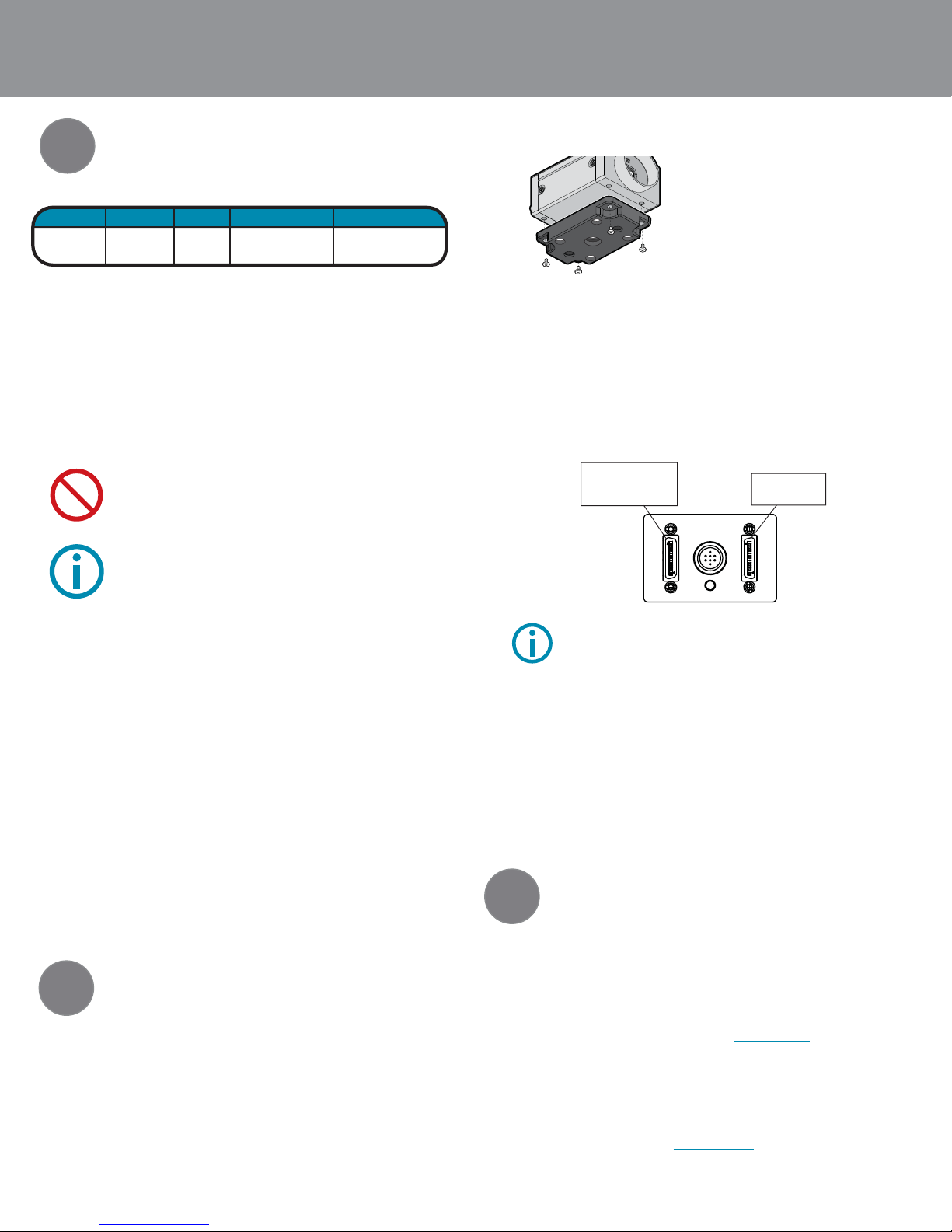
8. Connect the Camera Link PCIe card and cable to the camera
• 85 MHz-certied cables are required. The maximum supported cable length is 5
meters. See reverse for recommended cables. For Base 2-tap conguration, use
base connector. For Full 8-tap conguration, use both base and full connectors
(two cables are required). Connectors are labelled on the camera.i
9. Supply Power to the Camera
Connect a 12 V DC power supply to the camera’s GPIO port. The power supply
wiring harness must be compatible with a Hirose HR25 8-pin female connector.
See reverse for a compatible wall-mount power adapter available for purchase from
Point Grey.
10. Confirm Successful Installation
To operate the camera, start the serial interface tool for your frame grabber and
reference the configuration file downloaded in Step 5.Control the camera using
the software instruction set described in the camera’sTechnical Reference manual,
downloadable from http://www.ptgrey.com/support/downloads/index.asp.
CPU RAM VIDEO PORTS
OS
4.2GHz
or equivalent
XP, Vista,
Windows 7 512MB
NVIDIA GeForce6
or later
128 MB RAM or more
Camera Link PCIe card
with Full CL interface
GETTING STARTED Gazelle
Cameral Link Digital Camera
• The ASA and ISO-compliant tripod
mounting bracket attaches to the camera
using the included M3 screws.The bracket
is included at no extra charge with every
Point Grey Gazelle.
114
13 26 14 1
13
26
Full Camera link
connector, for full
conguration (with BASE
connector)
BASE Camera Link
connector, for all
congurations
The Gazelle Technical Reference Manual can be downloaded from http://www.
ptgrey.com/support/downloads/index.asp. Our online Knowledge Base
(http://www.ptgrey.com/support/kb/index.asp) addresses the following issues:
• Article 88:Vertical bleeding or smearing from a saturated portion of an image
• Article 145: Image discontinuities or horizontal tearing of images when displayed on monitor
3Troubleshooting
For all general questions about please contact us at info@ptgrey.com.
For technical support (existing customers only) contact
us at www.ptgrey.com/support/contact/.
Main Office:
Mailing Address: Tel: +1 (604) 242-9937
Point Grey Research, Inc. Toll Free (N.America only): +1 (866) 765-0827
Richmond B.C. Canada Fax: +1 (604) 242-9938
12051 Riverside Way Email: sales@ptgrey.com
V6W 1K7
CONTACTING POINT GREY RESEARCH
6. Install theTripod Mounting Bracket (optional)
Some cable assemblies may be looser than others when connected to the SDR
connectors on the camera. We recommend applying a screwdriver to the cable
screw pins to secure the connection.


