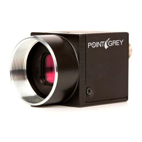
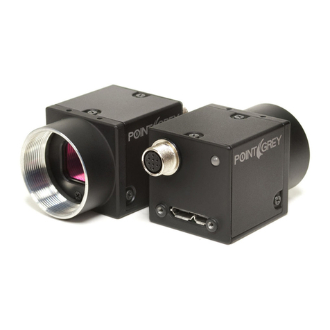
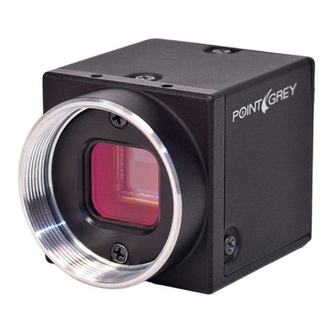
Point Grey Grasshopper Product manual

Grasshopper®
Technical Reference Manual
Version 1.5
Revised November 26, 2010
Point Grey Research
®
Inc.
12051 Riverside Way •Richmond, BC •Canada •V6W 1K7 •T(604) 242-9937 •www.ptgrey.com
Copyright © 2010 Point Grey Research Inc. All Rights Reserved.

Point Grey Research Grasshopper Technical Reference Table of Contents
Revised 26-Nov-10
Copyright (c) 2010 Point Grey Research Inc.
2
FCC Compliance Information
This equipment has been tested and found tocomply with thelimits for a Class Adigital device,
pursuant toPart 15 of the FCC Rules. Theselimits are designed toprovide reasonable
protection against harmful interference when the equipment is operated in a commercial
environment. This equipment generates, uses, and canradiateradiofrequencyenergy and, if not
installedand usedin accordance with theinstruction manual, maycause harmfulinterference to
radio communications. Operation of this equipment in a residential area is likely to cause harmful
interference in which case the user will berequired to correct the interferenceat his own
expense.
You are cautioned that any changes or modifications not expressly approved in this manual could
void your authority to operate this equipment.
Hardware Warranty
Point Grey Research
®
Inc. (Point Grey) warrants to the Original Purchaser that the Camera
Module provided with this package is guaranteed to be free from material and manufacturing
defects for a period of two(2) years. Should a unit fail during this period, Point Grey will, at its
option,repair or replace the damaged unit. Repaired or replaced units will be covered forthe
remainderof the originalequipment warrantyperiod. This warranty does not applyto unitsthat,
after being examined by PointGrey, have been found to havefailed due to customer abuse,
mishandling, alteration, improper installation or negligence. If the original camera module is
housed within a case, removing the case for any purpose voids this warranty.
Point Grey Research, Inc. expressly disclaims and excludes all other warranties, express, implied
and statutory, including, but without limitation, warranty of merchantability and fitness for a
particular application or purpose. In no event shall Point Grey Research, Inc. be liable to the
Original Purchaser or any third party for direct, indirect,incidental, consequential, special or
accidental damages, including without limitation damages for business interruption, loss of profits,
revenue, data or bodily injury or death.
WEEE
The symbol indicates that this product may not be treated as household
waste. Please ensure this product is properly disposed as inappropriate
waste handling of this product may cause potential hazards to the
environment and human health. For more detailed information about
recycling of this product, please contact Point Grey Research.
Trademarks
Point Grey Research, PGR, the Point Grey Research, Inc. logo, Chameleon, Digiclops,
Dragonfly, Dragonfly Express, Firefly, Flea, FlyCapture, Gazelle, Grasshopper, Ladybug, and
Triclops are trademarks or registered trademarks of Point Grey Research, Inc. in Canada and
other countries.

Point Grey Research Grasshopper Technical Reference Table of Contents
Revised 26-Nov-10
Copyright (c) 2010 Point Grey Research Inc.
3
Table of Contents
Table of Contents.....................................................................................3
List of Figures ..........................................................................................5
List of Tables............................................................................................5
1Introduction......................................................................................6
1.1. Grasshopper Overview...............................................................................6
1.1.1. Image Acquisition...........................................................................6
1.1.2. Image Processing..........................................................................6
1.1.3. Camera and Device Control...........................................................7
1.1.4. Mechanics and Form Factor...........................................................7
1.2. Using This Manual......................................................................................7
1.3. Camera Specifications................................................................................8
1.3.1. Spectral Response.........................................................................9
1.3.2. Common CCD Artifacts................................................................10
1.3.3. Dual Tap Sensor Information........................................................10
1.4. System Requirements...............................................................................10
1.4.1. Laptop / Notebook Considerations ...............................................11
1.4.2. Macintosh and Linux OS Support.................................................11
1.5. Controlling the Camera.............................................................................11
1.5.1. FlyCap Demo Program ................................................................11
1.5.2. Custom Applications Built with the FlyCapture API.......................11
1.5.3. Third-Party Software Applications ................................................11
1.6. Camera Control Command Registers........................................................12
1.7. Handling Precautions and Camera Care...................................................12
1.7.1. Case Temperature and Heat Dissipation......................................12
1.8. Camera Accessories.................................................................................13
2Camera Physical Properties.........................................................14
2.1. Physical Description..................................................................................14
2.2. Camera Dimensions.................................................................................15
2.3. Lens Setup and Compatibility....................................................................15
2.4. Dust Protection.........................................................................................16
2.5. Mounting...................................................................................................16
2.5.1. Using the Case............................................................................16
2.5.2. Using the Tripod Mounting Bracket...............................................16
2.6. Infrared Cut-Off Filters..............................................................................17
3Camera Interface ...........................................................................18
3.1. IEEE-1394b Connector.............................................................................18
3.1.1. Daisy Chaining.............................................................................18
3.2. Cables......................................................................................................19
3.3. Host Adapter Card....................................................................................19
3.4. Camera Power..........................................................................................19
3.5. General Purpose Input/Output (GPIO).......................................................20

Point Grey Research Grasshopper Technical Reference Table of Contents
Revised 26-Nov-10
Copyright (c) 2010 Point Grey Research Inc.
4
3.5.1. GPIO Electrical Characteristics....................................................21
3.6. Status Indicator LED.................................................................................21
4Camera Operations and Features................................................22
4.1. General Camera Properties ......................................................................23
4.2. Standard Data Formats, Modes and Frame Rates.....................................23
4.3. Frame Rates and Camera Bandwidth .......................................................25
4.3.1. Maximum Number of Cameras on a Single Bus ...........................25
4.3.2. Exceeding Bandwidth Limitations Using Format_7 with Multiple
Cameras...................................................................................................26
4.3.3. Calculating Maximum Possible Frame Rate .................................26
4.3.4. Dual Packet Mode........................................................................26
4.4. Customizable Data Formats and Modes....................................................27
4.4.1. Calculating Format_7 Frame Rates..............................................34
4.4.2. Subsampling and Binning in Format_7.........................................34
4.5. Image Acquisition .....................................................................................35
4.5.1. Camera Power.............................................................................35
4.5.2. Shutter.........................................................................................35
4.5.3. Gain.............................................................................................36
4.5.4. Auto Exposure.............................................................................36
4.5.5. Extended Shutter Times...............................................................37
4.5.6. Automatic Inter-Camera Synchronization .....................................38
4.5.7. Frame Rate Control .....................................................................38
4.5.8. Pixel Binning and Region of Interest Modes .................................38
4.5.9. Y16 (16-bit Mono) Image Acquisition............................................39
4.5.10. Asynchronous (External) Trigger Modes.....................................39
4.5.11. On-Camera Frame Buffer...........................................................41
4.5.12. High Dynamic Range (HDR) Mode.............................................42
4.6. Image Processing.....................................................................................42
4.6.1. Color and Greyscale Conversion..................................................42
4.6.2. Lookup Table and Gamma...........................................................43
4.6.3. Saturation....................................................................................44
4.6.4. Sharpness ...................................................................................44
4.6.5. White Balance..............................................................................44
4.6.6. Image Flip / Mirror........................................................................45
4.6.7. Test Pattern.................................................................................45
4.6.8. Embedded Image Information......................................................46
4.7. Camera and Device Control......................................................................46
4.7.1. Voltage Sensor............................................................................46
4.7.2. Programmable Strobe Output.......................................................46
4.7.3. RS-232 Serial Port.......................................................................46
4.7.4. Memory Channel Storage of Camera Settings..............................47
4.7.5. User Data Flash...........................................................................47
4.7.6. Camera Upgrades........................................................................47
Appendix A: Spectral Response Curves..............................................48
Appendix B: Memory Channel Registers.............................................54
Appendix C: Glossary............................................................................55
Appendix D: Technical Support Resources.........................................57
Appendix E: Contacting Point Grey Research ....................................58
Point Grey Research Grasshopper Technical Reference List of Figures
Revised 26-Nov-10
Copyright (c) 2010 Point Grey Research Inc.
5
Appendix F: Revision History...............................................................59
List of Figures
Figure 1: Dimensional drawing......................................................................................15
Figure 2: IEEE-1394b connector pin configuration.........................................................18
Figure 3: GPIO schematic.............................................................................................20
Figure 4: Grasshopper external trigger timing characteristics.........................................40
Figure 5: Relationship between video mode change and triggering................................41
Figure 6: Test pattern sample image (Mono and YUV formats)......................................45
List of Tables
Table 1: IEEE-1394b connector pin configuration..........................................................19
Table 2: GPIO pin assignments.....................................................................................20
Table 3: Status indicator LED descriptions....................................................................21
Table 4: Supported video formats, modes and frame rates............................................24
Table 5: Supported partial image (Format 7) video formats and modes for GRAS-03K2C
.............................................................................................................................28
Table 6: Supported partial image (Format 7) video formats and modes for GRAS-03S3M
.............................................................................................................................29
Table 7: Supported partial image (Format 7) video formats and modes for GRAS-14S3C
.............................................................................................................................30
Table 8: Supported partial image (Format 7) video formats and modes for GRAS-14S5C
.............................................................................................................................31
Table 9: Supported partial image (Format 7) video formats and modes for GRAS-20S4C
.............................................................................................................................32
Table 10: Supported partial image (Format 7) video formats and modes for GRAS-50S5C
.............................................................................................................................34
Table 11: Extended shutter minimum and maximum times............................................37

Point Grey Research Grasshopper Technical Reference Introduction
Revised 26-Nov-10
Copyright (c) 2010 Point Grey Research Inc.
6
1 Introduction
1.1. Grasshopper Overview
The Grasshopper digital camera line offers high megapixel resolution and an ultra fast IEEE-
1394b 800Mb/s digital interface. Attractive pricing makes these powerful cameras ideal for OEMs
and system integrators who need compact systems that deliver 1.4M, 2.0M or 5.0M images at
high frame rates. The Grasshopper cameras are particularly effective in demanding imaging
applications such as those used in electronics manufacturing, life sciences and microscopy,
surveillance and security, and ITS.
Users are encouraged to download TAN2007004 from www.ptgrey.com/products/grasshopper for
detailed information on how to transition applications from the Scorpion to the Grasshopper.
Refer to Knowledge Base Article 206 for a complete overview of the features and benefits of the
IEEE-1394b standard.
LAll model-specific information presented in this manual reflects
functionality available in firmware version 0.9.1.48.
To check the camera firmware version, consult our knowledge base:
www.ptgrey.com/support/kb/index.asp?a=4&q=94.
1.1.1. Image Acquisition
Feature Description
IEEE-1394b Bandwidth 800Mb/s interface allows full color RGB output at high data rates
Automatic Synchronization Multiple Grasshoppers on the same 1394b bus automatically sync
Programmable Exposure User-programmable shutter, gain, and black clamp settings via software
Fast Frame Rates Faster standard frame rates plus pixel binning and ROI support
Multiple Trigger Modes Bulb-trigger mode, multiple triggered exposures before readout
Trigger at Full Frame Rate Overlapped trigger input, image acquisition and transfer
1.1.2. Image Processing
Feature Description
Color Conversion On-camera conversion to YUV411, YUV422 and RGB formats
Image Processing On-camera control of sharpness, hue, saturation, gamma, LUT
Image Flip / Mirror Horizontal image flip (mirror image)
Embedded Image Info Pixels contain frame-specific info (e.g. shutter, 1394 cycle time)
Test Pattern Continuous static image for testing and development

Point Grey Research Grasshopper Technical Reference Introduction
Revised 26-Nov-10
Copyright (c) 2010 Point Grey Research Inc.
7
1.1.3. Camera and Device Control
Feature Description
Auto White Balance Auto and one-push white balance for easy color balancing
Frame Rate Control Fine-tune frame rates for video conversion (e.g. PAL @ 24 FPS)
Improved Strobe Output Increased drive strength, configurable strobe pattern output
RS-232 Serial Port Provides serial communication via GPIO TTL digital logic levels
Memory Channels Non-volatile storage of camera default power-up settings
Broadcast Properties Apply settings (e.g. shutter, gain) to all cameras on the same bus
Voltage Sensor Monitors sensor voltages to ensure optimal image quality
Camera Upgrades Firmware upgradeable in field via IEEE-1394 interface.
1.1.4. Mechanics and Form Factor
Feature Description
Compact Design 44mm x 29mm x 58mm, 104 grams
Industry Standard Mechanics ASA/ISO-compliant mounting bracket and C-mount lens holder
Jack Screw Connector 1394b cable jack screws provide secure connection
1.2. Using This Manual
This manual attempts to provide the user with a detailed specification of the Grasshopper camera
system. The reader should be aware that the camera system is a complex and dynamic system –
if any errors or omissions are found during experimentation, please contact us.
This document is subject to change without notice.
Many of the operational descriptions included in this manual are intended as general overviews,
and may not present the detailed information required for developing specific applications. For
additional details and operational descriptions, refer to the following resources that can be
downloaded from our website at www.ptgrey.com/support/downloads/:
•Point Grey Digital Camera Register Reference
•FlyCapture User Manual
•TAN2004004: Synchronizing to an external signal using DCAM 1.31 Trigger Mode_0
•TAN2004001: Configuring and testing the RS-232 serial port
•TAN2005002: Setting a GPIO pin to strobe using DCAM 1.31 Strobe Signal Output
•TAN2005003: Setting a GPIO pin to output a strobe signal pulse pattern
•TAN2005004: Buffering a GPIO pin output signal to drive an external device
•TAN2007004: A guide to transitioning from Scorpion®to Grasshopper®
•TAN2007004: Accessing the On-Camera Frame Buffer

Point Grey Research Grasshopper Technical Reference Introduction
Revised 26-Nov-10
Copyright (c) 2010 Point Grey Research Inc.
8
1.3. Camera Specifications
Specification 03K2 03S3 14S3 14S5 20S4 50S5
Imaging
Sensor
Kodak® KAI-
0340-
ABB/CBA-CB-
AA-Dual 1/3”
progressive
scan CCD
Sony®
ICX414 1/2”
progressive
scan CCD
Sony® ICX267
1/2”
progressive
scan CCD
Sony®
ICX285 2/3”
progressive
scan CCD
Sony® ICX274
1/1.8”
progressive
scan CCD
Sony® ICX625
2/3”
progressive
scan CCD
Maximum
Resolution 640(H) x 480
(V) 648(H) x
488(V) 1384(H) x
1032(V) 1384(H) x
1036(V) 1624(H) x
1224(V) 2448(H) x
2048(V)
Sensor Pixel
Size 7.4 x 7.4µm 9.9 x 9.9µm 4.65 x 4.65µm 6.45 x
6.45µm 4.4 x 4.4µm 3.45 x 3.45µm
Maximum FPS See sections 4.2 and 4.4 for more information
Digital
Interface Dual bilingual 9-pin IEEE-1394b for camera control, video data transmission and daisy
chaining
Transfer
Rates 100, 200, 400, 800 Mbit/s
A/D Converter Analog Devices 14-bit analog-to-digital converter
Max Pixel
Clock 40 MHz 26 MHz 40 MHz 28 MHz 67 MHz 32 MHz
Video Data
Output 8, 16 and 24-bit digital data (see Supported Data Formats)
Image Data
Formats Y8, Y16 (all models), RGB, YUV411, YUV422, YUV444, 8-bit and 16-bit raw Bayer data
(color models)
Partial Image
Modes Pixel binning and region of interest modes available via Format_7
General
Purpose I/O
8-pin Hirose HR25 general purpose input/output connector
4 pins for external trigger, strobe or serial data / 1 pin +3.3V / 1 VEXT pin to externally
power the camera
Automatic / manual / one-push gain modes
Gain 0dB to 24dB
Automatic / manual / one-push shutter modes
Programmable through software or through input trigger signal
0.01ms to 66.63ms @ 15 FPS
Shutter
Extended shutter modes for exposure times longer than 5 seconds
Image
Processing On-board raw Bayer color interpolation, hue, saturation, sharpness, gamma, programmable
LUT, horizontal image flip, test pattern output
Gamma 0.50 to 4.00
Trigger Modes DCAM v1.31 Trigger Modes 0, 1, 3, 14, and 15
* Signal To
Noise Ratio 56 dB 64 dB 60 dB 65 dB 59 dB 57 dB
* Peak QE
Wavelength 460 nm 500 nm 459 nm 470 nm 460 nm 520 nm
* Peak QE
V
alue 46 % 45 % 52 % 64 % 60 % 56 %
* Full Well
Depth 19426 e- 31370 e- 9159 e- 16964 e- 13942 e- 6486 e-
* Dark Noise 21.57 e-/s 13.61 e-
/
s 0.53 e-
/
s 6.38 e-
/
s 9.39 e-
/
s 3.19 e-/s
* Dark Current 187 e-/s 331 e-
/
s 1.84 e-
/
s 175 e-
/
s 122 e-
/
s 34 e-/s
* Read Noise 84 e- 41 e- 59 e- 33 e- 61 e- 78 e-
* Average 46 °C 37 °C 45 °C 36 °C 42 °C 38 °C

Point Grey Research Grasshopper Technical Reference Introduction
Revised 26-Nov-10
Copyright (c) 2010 Point Grey Research Inc.
9
Operating
Temperature
Dimensions 44mm x 29mm x 58mm (excluding lens holder, without optics)
Mass 104 grams (without optics)
Lens Mount C-mount
Camera
Specification IIDC 1394-based Digital Camera Specification v1.31
Voltage
Requirements 8-30V, via IEEE-1394b interface or 8-pin GPIO connector
Power
Requirements
(max) 3.9W 2.9W 3.0W 3.1W 3.4W 3.8W
Emissions
Compliance Complies with CE rules and Part 15 Class A of FCC Rules
Operating
Temperature 0° to 40°C
Storage
Temperature -30° to 60°C
Warranty Two years
Operating
Relative
Humidity
20 to 80% (no condensation)
Storage
Relative
Humidity
20 to 95% (no condensation)
* Measurements taken under the following conditions: Gain: 0 dB; Pixel Format: Format_7 Mode 0; Resolution: Max; Frame Rate: Max;
Shutter: 1 ms;
1.3.1. Spectral Response
LAll color models are equipped with an optical filter that prevents
infrared light from reaching the image sensor. This filter is discussed in
the section on Infrared Cut-Off Filters.
For spectral response curves, see Appendix A: Spectral Response Curves.

Point Grey Research Grasshopper Technical Reference Introduction
Revised 26-Nov-10
Copyright (c) 2010 Point Grey Research Inc.
10
1.3.2. Common CCD Artifacts
The following section describes issues typical of CCD sensors and possible solutions.
•Dead / Hot Pixels
It is possible for one or more pixels in the CCD sensor array to stop responding. This will
result in a situation where the pixel will always appear black (dead), or white (hot/stuck).
This is generally not anissue except invery rare cases.
•Bright Pixels
Cosmic rays have the ability to cause images to have artifacts which look like hot pixels
which are randomly distributed throughout the image. This is most apparent when th
e
camera is running at a high temperature or the gain is set to a high amount. It is
impossible to prevent cosmic rays from reaching theCCD.
•Vertical Smear
When a strong light source is shot on the camera, there may be a vertical smear above
and below the position of the actual light source. This is a byproduct of the interline
transfer system usedto extract data from the CCD.
1.3.3. Dual Tap Sensor Information
The Grasshopper 50S5M/C and 03K2M/C models feature dual tap CCDs. This means that the
CCD has two outputs running simultaneously in order to provide a larger data rate, thus resulting
in a higher frame rate. However, the CCD is generally unable to provide the left and right halves
of the image at an equal intensity. Therefore in order to maintain image quality, the Grasshopper
has been calibrated to correct for imbalances between the left and right halves. However, there
may be situations where the boundary between the left and right halves of the images can be
seen, such as images with high gain values.
1.4. System Requirements
•Processor
Recommended– Intel Pentium®4 2.0 GHz or compatible processor
Minimum – Intel Pentium III 800 MHz or compatible processor
•Memory
Recommended– 2GB
Minimum - 256MB
•AGP video card with 64 MB video memory (128 MB recommended)
•Bus Configuration
Recommended– PCI Express (PCI-e card not included) or 64-bit PCI slot
Minimum – 32-bit standard PCI slot forthe IEEE-1394 card
•Microsoft Windows XP Service Pack 1
•Microsoft Visual C++ 6.0 (to compile and run example code)

Point Grey Research Grasshopper Technical Reference Introduction
Revised 26-Nov-10
Copyright (c) 2010 Point Grey Research Inc.
11
1.4.1. Laptop / Notebook Considerations
Some 1394 PCMCIA cards for laptop / notebook computers require a 4-pin cable. A 4-pin cable does no
t
provide power and will therefore not work with Point Grey cameras, which require a 6-pin connector (the
additional two pins provide power). For suggestions on how to provide power in these circumstances,
consultthe followingknowledge base article:
KB Article 93: www.ptgrey.com/support/kb/index.asp?a=4&q=93
1.4.2. Macintosh and Linux OS Support
Users wishing to operate their Point Grey camera on the Macintosh OS/X or Linux operating
systems should consult the following knowledge base articles:
Macintosh support: www.ptgrey.com/support/kb/index.asp?a=4&q=173
Linux support: www.ptgrey.com/support/kb/index.asp?a=4&q=17
1.5. Controlling the Camera
The Grasshopper can be controlled by the following types of applications:
1.5.1. FlyCap Demo Program
The FlyCap application is a generic streaming image viewer included with the FlyCapture
®
SD
K
that can be used to test many of the capabilities of your compatible PGR IEEE-1394 camera. It
allows you to view a live video stream from the camera, save individual images or .avi movi
e
clips, adjust the various video formats, frame rates, properties and settings of the camera, and
access camera registers. It is an easy-to-use program that can be used to test many of the
capabilities of your PGR IEEE-1394 camera system. Consult the PGR FlyCapture User Manua
l
for moreinformation.
1.5.2. Custom Applications Built with the FlyCapture API
PGR FlyCapture includes a full Application Programming Interface that allows customers to
create custom applications to control Point Grey Imaging Products. The SDK provides a numbe
r
of sample programs and source code that is meant to help the advanced programmer get started
using the FlyCapture API. Examples range from simple console programs that demonstrate the
basic functionality of the API, such as PGRFlyCaptureTest, to more complex examples such as
the MFC application FlyCap.
1.5.3. Third-Party Software Applications
The following knowledge base article provides information on Point Grey IEEE-1394 camer
a
compatibility with third-party software development kits, applications, camera drivers, and
integrated development environments (IDEs):
KB Article 152: www.ptgrey.com/support/kb/index.asp?a=4&q=152

Point Grey Research Grasshopper Technical Reference Introduction
Revised 26-Nov-10
Copyright (c) 2010 Point Grey Research Inc.
12
1.6. Camera Control Command Registers
For a complete description of the Camera Control Command Registers implemented on the
camera, please refer to the Point Grey Research Digital Camera Register Reference, included
with theFlyCapture SDK and downloadable from www.ptgrey.com/support/downloads/.
1.7. Handling Precautions and Camera Care
[Do not open the camera housing. Doing so voids the Hardware
Warranty described at the beginning ofthis reference manual.
Your Point Grey digital camera module is a precisely manufactured device and should be handled
withcare. Here are some tips on how tocare for the device.
•Avoid electrostatic charging. Please consult the following knowledge base article for more
details: www.ptgrey.com/support/kb/index.asp?a=4&q=42.
•Users who have purchased a bare board camera should take the following additional
protective measures:
oEither handle bare handed or use non-chargeable gloves, clothes or material.
Also, use conductive shoes.
oInstall a conductive mat on the floor or working table to prevent the generation of
static electricity.
•When handling the camera unit, avoid touching the lenses. Fingerprints will affect the quality
of the image produced by the device.
•To clean the lenses, use a standard camera lens cleaning kit or a clean dry cotton cloth. Do
notapply excessive force.
•To clean the imaging surface of your CCD, follow the steps outlined in
www.ptgrey.com/support/kb/index.asp?a=4&q=66.
•Our cameras are designed for an office environment or laboratory use. Extended exposure
to bright sunlight, rain, dusty environments, etc. may cause problems with the electronics and
theoptics of the system.
•Avoid excessive shaking, dropping orany kind of mishandlingof the device.
1.7.1. Case Temperature and Heat Dissipation
The Grasshopper is an ultra-compact camera. As a result of packing the Grasshopper electronics
into a small space, the outer case of the camera can become very warm to the touch when
running in some high data rate video modes. The case can reach temperatures up to 45°Celsius
under normal operating conditions. This is expected behaviour and will not damage the camera
electronics.

Point Grey Research Grasshopper Technical Reference Introduction
Revised 26-Nov-10
Copyright (c) 2010 Point Grey Research Inc.
13
If reducing heat is a concern, users can use a cooling fan to set up a positive air flow around the
camera, taking into consideration the following precautions:
•Mount the camera on a heat sink, such as a camera mounting bracket, made out of a
heat-conductive material like aluminum.
•Make sure the flow of heat from the camera case to the bracket is not blocked by a non-
conductive material like plastic.
•Make sure the camera has enough open space around it to facilitate the free flow of air.
1.8. Camera Accessories
Accessories such as tripod mounts and lens holders are available from PGR – contact our Sales
team at sales@ptgrey.com for additional information. Links to FireWire/IEEE-1394 and digital
camera accessories can be found in the following knowledge base article:
KB Article 131: www.ptgrey.com/support/kb/index.asp?a=4&q=131.

Point Grey Research Grasshopper Technical Reference Camera Physical Properties
Revised 26-Nov-10
Copyright (c) 2010 Point Grey Research Inc.
14
2 Camera Physical Properties
2.1. Physical Description
1. Lens holder (C-
mount)
Attach any C-mount
lens or other optical
equipment. Consult
the section Lens
Setup and
Compatibility for full
details.
2. Glass / IR filter
system
Refer to the Dust
Protection and the
Infrared Cut-Off
Filters section for
more information.
3. M3x0.5 mounting
holes
Refer to the
Mounting section for
full details.
4. General Purpose I/O connector
The 8-pin GPIO connector is used for external triggering,
strobe output or digital I/O. Refer to the General Purpose
Input/Output section for more information.
5. Status LED
This light indicates the current state of the Grasshopper
operation. Refer to the section Status Indicator LED.
6. IEEE-1394b connector
7. IEEE-1394b connector
The camera uses standard 9-pin 1394b connectors. M3
screw holes are located on either side of the connectors
for secure connections to the 9-pin locking 1394b cable.
See the IEEE-1394 Connector section for full connector
details.
8. M3x0.5 mounting holes
Refer to the Mounting section for full details.
3
1
2
3
4
5
6
7
8

Point Grey Research Grasshopper Technical Reference Camera Physical Properties
Revised 26-Nov-10
Copyright (c) 2010 Point Grey Research Inc.
15
2.2. Camera Dimensions
Figure 1: Dimensional drawing
2.3. Lens Setup and Compatibility
The lens holder is compatible with C-mount lenses. Lenses are not included with individual
cameras. To differentiate between C- and CS-mount lenses, consult the following article:
KB Article 98: www.ptgrey.com/support/kb/index.asp?a=4&q=98

Point Grey Research Grasshopper Technical Reference Camera Physical Properties
Revised 26-Nov-10
Copyright (c) 2010 Point Grey Research Inc.
16
2.4. Dust Protection
[Cameras are sealed when they are shipped. To avoid contamination,
seals should not be broken until cameras are ready for assembly at
customer's site.
Do not remove the protective glass. Doing so can void the Hardware
Warranty described at the beginning of this reference manual.
The case is designed to prevent dust from falling directly onto the CCD's protective glass surface.
This is achieved by placing a piece of clear glass (monochrome cameramodels) or IR cut-off filter
(color models) that sits above the surface of the CCD's glass. A removable plastic retainer keeps
this glass/filter system in place. By increasing the distance between the imaging surface and the
location of the potential dust particles, the likelihood of interference from the dust (assuming non-
collimated light) and the possibility ofdamage to the sensor during cleaning is reduced.
2.5. Mounting
2.5.1. Using the Case
The case is equipped with the following mounting holes:
•Two (2) M3x0.5mm mounting holes on the top of the case
•Four (4) M3x0.5mm mounting holes on the bottom of the case that can be used to attach
the camera directly to a custom mount or to the Grasshopper tripod mounting bracket
2.5.2. Using the Tripod Mounting Bracket
The Grasshopper tripod mounting bracket comes with the Development Kit, or can be purchased
separately by contacting sales@ptgrey.com. The bracket is equipped with four (4) M3 mounting
holes.

Point Grey Research Grasshopper Technical Reference Camera Physical Properties
Revised 26-Nov-10
Copyright (c) 2010 Point Grey Research Inc.
17
2.6. Infrared Cut-Off Filters
Point Grey Research color camera models are equipped with an additional infrared (IR) cut-off
filter. This filter can reduce sensitivity in the visible spectrum. The properties of this filter are
illustrated in the results below, which were obtained by Point Grey Research independent of
camera model.
In monochrome models, the IR filter is replaced with a transparent piece of glass.
The following are the properties of the IR filter/protective glass
1
:
Type Reflective
Material Schott D 263 T or BK7 equivalent for coating filters
Physical Filter Size 14 mm x 14 mm
Glass Thickness 1.0 mm
Dimensional Tolerance +/-0.1 mm`
Coating Filters Scott D 263 T
1
These properties apply to all imaging cameras except GRAS 14S5.
Related Knowledge Base Articles
ID Title URL
98 Understanding flange back
distance on C-mount and CS-
mount cameras
www.ptgrey.com/support/kb/index.asp?a=4&q=98

Point Grey Research Grasshopper Technical Reference Camera Interface
Revised 26-Nov-10
Copyright (c) 2010 Point Grey Research Inc.
18
3 Camera Interface
3.1. IEEE-1394b Connector
The camera has 2 standard 9-pin IEEE-1394b connectors (pin configuration shown below) that is
used for data transmission, camera control and powering the camera. For more detailed
information, consult the IEEE-1394b Standard document available from www.1394ta.org.
For a full description of the features and benefits of 1394b, refer to Knowledge Base Article 206.
3.1.1. Daisy Chaining
As the camera has 2 IEEE-1394b connectors, it is possible to connect multiple cameras (and/or
hubs) in a daisy-chained manner. This allows multiple cameras to be easily connected to a single
host controller. However, the maximum bandwidth available for all cameras is still restricted to
800Mbps (for IEEE-1394b) or 400Mbps (for IEEE-1394a).
LWhile the Grasshopper is an IEEE-1394b device, it is backward
compatible with the IEEE-1394a 400Mb/s standard, and can therefore
be connected to any 1394a OHCI host adapter using a 9- to 6-pin
cable (included with Grasshopper Development Kits).
Figure 2: IEEE-1394b connector pin configuration
Pin Signal Name Comment
1 TPB- Twisted Pair B (Minus)
2 TPB+ Twisted Pair B (Plus)
3 TPA- Twisted Pair A (Minus)
4 TPA+ Twisted Pair A (Plus)
5 TPA (R) Twisted Pair A (Reference Ground)
6 VG Power (Ground)
7 SC Status Contact (Reserved for Future Use)
8 VP Power (Voltage)
9 TPB (R) Twisted Pair B (Reference Ground)

Point Grey Research Grasshopper Technical Reference Camera Interface
Revised 26-Nov-10
Copyright (c) 2010 Point Grey Research Inc.
19
Table 1: IEEE-1394b connector pin configuration
3.2. Cables
The maximum 1394 cable length between any 1394 node (e.g. camera to PCI card, PCI card to
hub, etc.) is 4.5m, as specified by the IEEE-1394 standard. Standard, shielded twisted pai
r
copper cables must be used. Consultthe following knowledge base article for information on how
to extend the physical distance between the camera and the controlling host system:
KB Article 197: www.ptgrey.com/support/kb/index.asp?a=4&q=197
3.3. Host Adapter Card
All camera KITs (e.g. part numbers ending with “KIT”) come with a 3-port IEEE-1394 PCI hos
t
adapter card. For more information regarding the differences between various 1394 hos
t
adapters,consult the following knowledge base article:
KB Article 146: www.ptgrey.com/support/kb/index.asp?a=4&q=146
3.4. Camera Power
The 9-pin 1394b interface connects to a standard IEEE-1394 (FireWire) 9-pin cable and provides
a power connection between the camera and the host computer. The ideal input voltage is 12
V
DC; however, the camera is designed to handle voltages between 8V and 30V DC. The powe
r
consumption is outlined in the Camera Specifications section.
Some systems - such as laptop computers or those with several FireWire devices connected -
require an external power supply to power the camera. For suggestions on how to provide powe
r
in these circumstances, consult the following knowledge base article:
KB Article 93: www.ptgrey.com/support/kb/index.asp?a=4&q=93
Some PGR cameras allow the user to power-up or power-down components of the camera using
the DCAM CAMERA_POWER register 0x610. The exact components, e.g. image sensor, A/D
converter, other board electronics, will vary between camera models. Consult the PGR IEEE-
1394 Digital Camera Register Reference for more information.
When a camera is power cycled (power disengaged then re-engaged), the camera will revert to
its default factory settings, or if applicable, the last saved memory channel.

Point Grey Research Grasshopper Technical Reference Camera Interface
Revised 26-Nov-10
Copyright (c) 2010 Point Grey Research Inc.
20
3.5. General Purpose Input/Output (GPIO)
The Grasshopper has an 8-pin GPIO connector on the back of the case. The connector is a
Hirose HR25 8 pin connector (Mfg P/N: HR25-7TR-8SA). KIT contents include a prewired male
connector; refer to the diagram below for wire color-coding. Additional male connectors (Mfg P/N:
HR25-7TP-8P) can be purchased from Digikey (P/N: HR702-ND).
Diagram Pin Function Function
1 IO0 Input / Output (default Trigger_Src)
2 IO1 Input / Output
3 IO2 Input / Output / RS232 Transmit (TX)
4 IO3 Input / Output / RS232 Receive (RX)
5 GND
6 GND
7 VEXT Allows the camera to be powered externally
8 +3.3V Power external circuitry up to 150mA
Table 2: GPIO pin assignments
Figure 3: GPIO schematic
Inputs can be configured to accept external trigger signals. Outputs can be configured to send
an output signal, strobe, or PWM signal. To use the RS232 functionality, a level converter must
be used to convert the TTL digital logic levels to RS232 voltage levels. B&B Electronics
(http://www.bb-elec.com/) part number 232LPTTL can be used for this conversion.
For more information on using the RS232 serial port, download Technical Application Note
TAN2004001 from www.ptgrey.com/support/downloads/.
Other manuals for Grasshopper
1
Table of contents
Other Point Grey Digital Camera manuals

Point Grey
Point Grey Chameleon User manual

Point Grey
Point Grey Gazelle User manual

Point Grey
Point Grey Flea3 GigE Use and care manual

Point Grey
Point Grey Grasshopper2 User manual

Point Grey
Point Grey Grasshopper2 GS2-FW-14S5M / C User manual

Point Grey
Point Grey Grasshopper User manual

Point Grey
Point Grey Blackfly User manual

Point Grey
Point Grey Firefly MV FFMU-03MTM User manual

Point Grey
Point Grey Grasshopper2 User manual

Point Grey
Point Grey Gazelle User manual