Point Grey Flea3 GigE Use and care manual

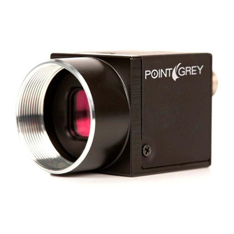
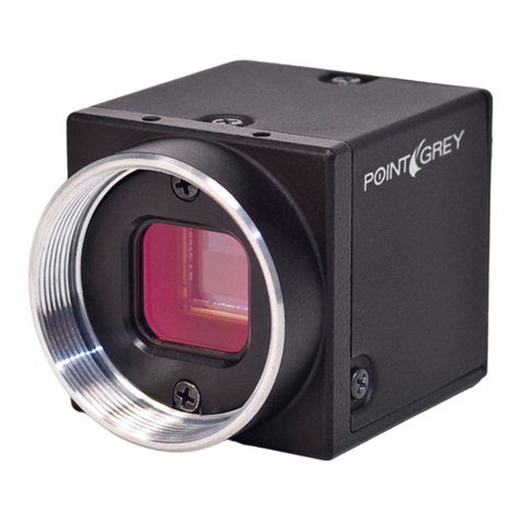
Flea3 GigE
GigE Digital Camera
Technical Reference
Version 7.0
Revised 10/29/2013
Point Grey Research®Inc.
12051 Riverside Way • Richmond, BC • Canada • V6W 1K7 •T (604) 242-9937 • www.ptgrey.com
Copyright © 2010-2013 Point Grey Research Inc. All Rights Reserved.

FCC Compliance
This device complies with Part 15 of the FCC rules. Operation is subject to the following two conditions:
(1) This device may not cause harmful interference, and (2) this device must accept any interference
received, including interference that may cause undesirable operation.
Korean EMCCertification
The KCC symbol indicates that this product complies with Korea’s Electrical Communication Basic Law
regarding EMC testing for electromagnetic interference (EMI) and susceptibility (EMS).
Hardware Warranty
The warranty for the Flea3 GigE camera is 3 years. For detailed information on how to repair or replace
your camera, please see the terms and conditions on our website.
WEEE
The symbol indicates that this product may not be treated as household waste. Please ensure
this product is properly disposed as inappropriate waste handling of this product may cause
potential hazards to the environment and human health. For more detailed information
about recycling of this product, please contact Point Grey Research.
Trademarks
Point Grey Research, PGR, the Point Grey Research, Inc. logo, Blackfly, Bumblebee, Chameleon, Digiclops,
Dragonfly, Dragonfly Express, Firefly, Flea, FlyCapture, Gazelle, Grasshopper, Ladybug, Triclops and Zebra
are trademarks or registered trademarks of Point Grey Research, Inc. in Canada and other countries.

Point Grey Flea3 GigE Technical Reference
Table of Contents
Contacting Point Grey Research i
1 Flea3 GigE Specifications 1
1.1 Flea3 GigE Specifications 1
1.2 Handling Precautions and Camera Care 3
1.2.1 Case Temperature and Heat Dissipation 3
1.3 Analog-to-Digital Converter 5
2 Flea3 GigE Installation 6
2.1 Before You Install 6
2.1.1 Will your system configuration support the camera? 6
2.1.2 Do you have all the parts you need? 6
2.1.3 Do you have a downloads account? 6
2.2 Installing Your Interface Card and Software 7
2.3 Installing Your Camera 9
2.4 Configuring Camera Setup 11
2.4.1 Configuring Camera Drivers 11
2.4.2 Configuring the IP Address 11
2.4.3 Allocating Bandwidth 12
2.4.3.1 Packet Size 12
2.4.3.2 Packet Delay 13
2.4.3.3 Determining Bandwidth Requirements 13
2.4.4 Configuring Other Network Settings 14
2.4.4.1 Stream Channel Destination Address 14
2.4.4.2 Heartbeat 15
3 Tools to Control the Flea3 GigE 16
3.1 Using FlyCapture 16
3.1.1 FlyCap Program 16
3.1.2 Custom Applications Built with the FlyCapture API 16
3.2 Using GenICam Applications 17
3.3 Using GigE Vision Bootstrap Registers 17
3.4 Using Control and Status Registers 18
4 Flea3 GigE Physical Interface 19
4.1 Flea3 GigE Physical Description 19
4.2 Flea3 GigE Dimensions 20
4.3 Mounting with the Case or Mounting Bracket 20
4.3.1 Tripod Adapter Dimensions 21
4.4 Lens Mounting 22
Revised 10/29/2013
Copyright ©2010-2013 Point Grey Research Inc.

Point Grey Flea3 GigE Technical Reference
4.4.1 Back Flange Distance 22
4.5 Dust Protection 23
4.6 Infrared Cut-Off Filters 24
4.7 Camera Interface and Connectors 25
4.7.1 Ethernet Connector 25
4.7.2 Interface Cables 25
4.7.3 Interface Card 25
4.7.4 General Purpose Input/Output (GPIO) 25
5 General Flea3 GigE Operation 27
5.1 Powering the Camera 27
5.2 User Sets (Memory Channels) 27
5.2.1 GenICam User Set Control 28
5.3 On-Camera Frame Buffer 28
5.4 Non-Volatile Flash Memory 29
5.5 Camera Firmware 29
5.5.1 Determining Firmware Version 30
5.5.2 Upgrading Camera Firmware 30
6 Input/Output Control 31
6.1 General Purpose Input/Output (GPIO) 31
6.2 GPIO Modes 32
6.2.1 GPIO Mode 0: Input 32
6.2.2 GPIO Mode 1: Output 32
6.2.3 GPIO Mode 2: Asynchronous (External) Trigger 32
6.2.4 GPIO Mode 3: Strobe 32
6.2.5 GPIOMode 4: Pulse Width Modulation (PWM) 32
6.3 GenICam Digital Input/Output Control 33
6.4 Programmable Strobe Output 34
6.5 Pulse Width Modulation (PWM) 34
6.6 Serial Communication 35
6.7 Debouncer 35
6.8 GPIO Electrical Characteristics 37
7 Image Acquisition 39
7.1 Asynchronous Triggering 39
7.1.1 GenICam Acquisition Control 39
7.1.2 Standard External Trigger (Mode 0) 41
7.1.3 Bulb Shutter Trigger (Mode 1) 42
7.1.4 Skip Frames Trigger (Mode 3) 43
7.1.5 Multiple Exposure Preset Trigger (Mode 4) 44
7.1.6 Multiple Exposure Pulse Width Trigger (Mode 5) 45
Revised 10/29/2013
Copyright ©2010-2013 Point Grey Research Inc.
Point Grey Flea3 GigE Technical Reference
7.1.7 Low Smear Trigger (Mode 13) 46
7.1.8 Overlapped Exposure Readout Trigger (Mode 14) 47
7.1.9 Multi-Shot Trigger (Mode 15) 48
7.2 External Trigger Timing 49
7.3 Camera Behavior Between Triggers 49
7.4 Changing Video Modes While Triggering 50
7.5 Asynchronous Software Triggering 51
8 Flea3 GigE Attributes 52
8.1 Pixel Formats 52
8.1.1 Raw 52
8.1.2 Mono 52
8.1.3 RGB 52
8.1.4 YUV 52
8.2 Video Modes Overview 54
8.2.1 Video Mode Descriptions 55
8.3 GenICam Image Format Control 57
8.4 Frame Rates 58
8.4.1 Calculating Maximum Possible Frame Rate 58
8.4.2 FL3-GE-03S2 Video Modes and Frame Rates 59
8.4.3 FL3-GE-08S2 Video Modes and Frame Rates 60
8.4.4 FL3-GE-13S2 Video Modes and Frame Rates 61
8.4.5 FL3-GE-14S3 Video Modes and Frame Rates 62
8.4.6 FL3-GE-20S4 Video Modes and Frame Rates 63
8.4.7 FL3-GE-28S4 Video Modes and Frame Rates 65
8.4.8 FL3-GE-50S5 Video Modes and Frame Rates 67
8.5 Shutter Type 69
8.5.1 Global Shutter 69
8.6 Overview of Imaging Parameters 70
8.7 GenICam Analog Control 71
8.8 Brightness 72
8.9 Shutter Time 72
8.10 Gain 73
8.11 Auto Exposure 74
8.12 Sharpness 75
8.13 Gamma and Lookup Table 75
8.14 High Dynamic Range (HDR) Imaging 77
8.15 Image Flip/Mirror 77
8.16 Embedded Image Information 77
8.17 White Balance 79
Revised 10/29/2013
Copyright ©2010-2013 Point Grey Research Inc.

Point Grey Flea3 GigE Technical Reference
8.18 Bayer Color Processing 80
8.19 Hue 81
8.20 Saturation 81
9 Troubleshooting 82
9.1 Support 82
9.2 Camera Diagnostics 83
9.3 Status Indicator LED 84
9.4 Test Pattern 84
9.5 Channel Balancing 85
9.6 Blemish Pixel Artifacts 86
9.6.1 Pixel Defect Correction 86
9.7 Vertical Smear Artifact 87
9.7.1 Smear Reduction 87
A FlyCapture API Code Samples 88
A.1 Setting a GPIOPin to Strobe Using the FlyCapture API 88
A.2 Setting a Standard Video Mode, Format and Frame Rate Using the FlyCapture API 88
A.3 Asynchronous Hardware Triggering Using the FlyCapture API 88
A.4 Setting Brightness Using the FlyCapture API 89
A.5 Setting Shutter Using the FlyCapture API 89
A.6 Setting Gain Using the FlyCapture API 89
A.7 Setting Auto Exposure Using the FlyCapture API 90
A.8 Setting Sharpness Using the FlyCapture API 90
A.9 Setting Gamma Using the FlyCapture API 90
A.10 Setting White Balance Using the FlyCapture API 91
A.11 Accessing Raw Bayer Data using FlyCapture 91
A.12 Setting Hue Using the FlyCapture API 91
A.13 Setting Saturation Using the FlyCapture API 92
B FlyCapture SDK Examples 93
B.1 AsyncTriggerEx 93
B.2 BusEventsEx 93
B.3 CustomImageEx 93
B.4 ExtendedShutterEx 94
B.5 FlyCap2CameraControl 94
B.6 FlyCap2_GTKmm 94
B.7 FlyCap2MFC 95
B.8 FlyCapture2GUI 95
B.9 FlyCapture2SimpleGUI_WPF 95
B.10 FlyCapture2Test 95
B.11 GigEGrabEx 96
Revised 10/29/2013
Copyright ©2010-2013 Point Grey Research Inc.
Point Grey Flea3 GigE Technical Reference
B.12 GrabCallbackEx 96
B.13 HighDynamicRangeEx 96
B.14 ImageEventEx 96
B.15 MultipleCameraEx 98
B.16 MultipleCameraWriteToDiskEx 98
B.17 MultiSyncEx 98
B.18 SaveImageToAviEx 98
B.19 SaveImageToFlashEx 98
B.20 SerialPortEx 99
C GenICam Features 100
C.1 Device Control 100
C.2 Analog Control 100
C.3 Image Format Control 101
C.4 Acquisition Control 102
C.5 Digital Input Output Control 103
C.6 Transport Layer Control 104
C.7 User Set Control 108
C.8 Chunk Data Control 108
D GigE Vision Bootstrap Registers 109
E Control and Status Registers 111
E.1 IMAGE_RETRANSMIT: 634h 111
E.2 DATA_FLASH_CTRL: 1240h 112
E.3 DATA_FLASH_DATA: 1244h 112
E.4 GPIO_CTRL_PIN: 1110h-1140h 113
E.5 GPIO_XTRA_PIN: 1114h-1144h 114
E.6 TRIGGER_MODE: 830h 114
E.7 PIXEL_CLOCK_FREQ: 1AF0h 115
E.8 AE_ROI: 1A70 – 1A74h 115
E.9 LUT: 80000h – 80048h 116
E.10 FRAME_INFO: 12F8h 118
E.11 INITIALIZE: 000h 119
E.12 TIME_FROM_INITIALIZE: 12E0h 119
E.13 LINK_UP_TIME: 12E4h 119
E.14 XMIT_FAILURE: 12FCh 120
E.15 VMODE_ERROR_STATUS: 628h 120
E.16 CAMERA_LOG: 1D00 – 1DFFh 120
E.17 LED_CTRL: 1A14h 120
E.18 PIXEL_DEFECT_CTRL: 1A60h 121
Revision History 122
Revised 10/29/2013
Copyright ©2010-2013 Point Grey Research Inc.

Point Grey Flea3 GigE Technical Reference Contacting Point Grey Research
Contacting Point Grey Research
For any questions, concerns or comments please contact us via the following methods:
Email General questions about Point Grey Research
Technical support (existing customers only)
Knowledge Base Find answers to commonly asked questions in our Knowledge Base
Downloads Download the latest documents and software
Main Office
Point Grey Research, Inc.
12051 Riverside Way
Richmond, BC, Canada V6W 1K7
Tel: +1 (604) 242-9937
Toll Free +1 (866) 765-0827
(North America only)
Fax: +1 (604) 242-9938
Email: sales@ptgrey.com
USA Tel: +1 (866) 765-0827
Email: na-sales@ptgrey.com
Europe and Israel
Point Grey Research GmbH Schwieberdinger Strasse
60
71636 Ludwigsburg
Germany
Tel: +49 7141 488817-0
Fax: +49 7141 488817-99
Email: eu-sales@ptgrey.com
Distributors
Japan ViewPLUS Inc. www.viewplus.co.jp
Korea Cylod Co. Ltd. www.cylod.com
China LUSTERLightVision Tech. Co., Ltd. www.lusterlighttech.com
Singapore, Malaysia &
Thailand Voltrium Systems Pte Ltd. www.voltrium.com.sg
Taiwan Apo Star Co., Ltd. www.apostar.com.tw
United Kingdom ClearView Imaging Ltd. www.clearviewimaging.co.uk
Revised 10/29/2013
Copyright ©2010-2013 Point Grey Research Inc. i
Point Grey Flea3 GigE Technical Reference Contacting Point Grey Research
About This Manual
This manual provides the user with a detailed specification of the Flea3 GigE camera system. The user should be aware
that the camera system is complex and dynamic – if any errors or omissions are found during experimentation, please
contact us. (See Contacting Point Grey Research.)
This document is subject to change without notice.
All model-specific information presented in this manual reflects functionality available in the model's
firmware version.
For more information see Camera Firmware.
Where to Find Information
Chapter What You Will Find
Flea3 GigE Specifications General camera specifications and specific model specifications, and camera properties.
Flea3 GigE Installation Instructions for installing the Flea3 GigE, as well as introduction to Flea3 GigE configuration.
Tools to Control the Flea3 GigE Information on the tools available for controlling the Flea3 GigE.
Flea3 GigE Physical Interface Information on the mechanical properties of the Flea3 GigE.
General Flea3 GigE Operation Information on powering the Flea3 GigE, monitoring status, user configuration sets, memory
controls, and firmware.
Input/Output Control Information on input/output modes and controls.
Image Acquisition Information on asynchronous triggering and supported trigger modes.
Flea3 GigE Attributes Information on supported imaging parameters and their controls.
Troubleshooting Information on how to get support, diagnostics for the Flea3 GigE, and common sensor
artifacts.
Appendix: FlyCapture API Code
Samples Examples of FlyCapture API code.
Appendix: FlyCapture SDK
Examples Sample programs provided with the FlyCapture SDK.
Appendix: GenICam Features Information on GenICam Feature controls.
Appendix: GigE Vision Bootstrap
Registers Information on GigEVision Bootstrap Registers.
Appendix: Control and Status
Registers Information on IIDCControl and Status Registers for functions not handled via GenICam.
Revised 10/29/2013
Copyright ©2010-2013 Point Grey Research Inc. ii

Point Grey Flea3 GigE Technical Reference Contacting Point Grey Research
Document Conventions
This manual uses the following to provide you with additional information:
A note that contains information that is distinct from the main body of text. For example,
drawing attention to a difference between models; or a reminder of a limitation.
A note that contains a warning to proceed with caution and care, or to indicate that the
information is meant for an advanced user. For example, indicating that an action may void
the camera's warranty.
If further information can be found in our Knowledge Base, a list of articles is provided.
Title Article
Title of the Article Link to the article on the Point Grey website
Related Knowledge Base Articles
If there are further resources available, a link is provided either to an external website, or to the SDK.
Title Link
Title of the resource Link to the resource
Related Resources
Revised 10/29/2013
Copyright ©2010-2013 Point Grey Research Inc. iii

Point Grey Flea3 GigE Technical Reference 1 Flea3 GigE Specifications
1 Flea3 GigE Specifications
The fully redesigned, next generation Flea3 camera series builds on the success of the ultra-compact Flea2 by adding
new Sony image sensors to the line-up. The Flea3 also offers a host of new features, including enhanced opto-isolated
GPIO; an on-camera frame buffer; non-volatile flash memory for user data storage; new trigger modes; and improved
imaging performance.
1.1 Flea3 GigE Specifications
Model Version MP Imaging Sensor
FL3-GE-03S1C-C
FL3-GE-03S1M-C
Color
Mono 0.3 MP
nSony ICX618 CCD, 1/4", 5.6 µm
nGlobal Shutter
n120 FPS at 648 x 488
FL3-GE-03S2C-C
FL3-GE-03S2M-C
Color
Mono 0.3 MP
nSony ICX424 CCD, 1/3", 7.4 µm
nGlobal Shutter
n82 FPS at 648 x 488
FL3-GE-08S2C-C
FL3-GE-08S2M-C
Color
Mono 0.8 MP
nSony ICX204 CCD, 1/3", 4.65 µm
nGlobal Shutter
n31 FPS at 1032 x 776
FL3-GE-13S2C-C
FL3-GE-13S2M-C
Color
Mono 1.3 MP
nSony ICX445 CCD, 1/3", 3.75 µm
nGlobal Shutter
n31 FPS at 1288 x 964
FL3-GE-14S3C-C
FL3-GE-14S3M-C
Color
Mono 1.4 MP
nSony ICX267 CCD, 1/2", 4.65 µm
nGlobal Shutter
n18 FPS at 1384 x 1032
FL3-GE-20S4C-C
FL3-GE-20S4M-C
Color
Mono 2.0 MP
nSony ICX274 CCD, 1/1.8", 4.4 µm
nGlobal Shutter
n15 FPS at 1624 x 1224
FL3-GE-28S4C-C
FL3-GE-28S4M-C
Color
Mono 2.8 MP
nSony ICX687 CCD, 1/1.8", 3.69 µm
nGlobal Shutter
n15 FPS at 1928 x 1448
FL3-GE-50S5C-C
FL3-GE-50S5M-C
Color
Mono 5.0 MP
nSony ICX655 CCD, 2/3", 3.45 µm
nGlobal Shutter
n8 FPS at 2448 x 2048
All Flea3 GigE Models
Imaging Performance
(EMVA 1288)
See the Imaging Performance Specification, which includes quantum efficiency,
saturation capacity (full well depth), read noise, dynamic range and signal to noise ratio.
A/DConverter 12-bit
Video Data Output 8, 12, 16 and 24-bit digital data
Revised 10/29/2013
Copyright ©2010-2013 Point Grey Research Inc. 1

Point Grey Flea3 GigE Technical Reference 1 Flea3 GigE Specifications
All Flea3 GigE Models
Image Data Formats Y8, Y16, Mono8, Mono12, Mono16, Raw8, Raw12, Raw16 (all models); RGB, YUV411,
YUV422, YUV 444 (color models)
Partial Image Modes Pixel binning and region of interest (ROI) modes
Image Processing Gamma, lookup table, hue, saturation, and sharpness
Shutter Global Shutter; Automatic/manual/one-push/extended shutter modes
0.03 ms to 32 seconds
Gain Automatic/manual/one-push modes
0 dB to 24 dB
Gamma 0.50 to 4.00, programmable lookup table
White Balance Automatic/manual/one-push modes
High Dynamic Range Cycle 4 gain and exposure presets
Color Processing On-camera in YUV or RGB format, or on-PC in Raw format
Digital Interface Gigabit Ethernet interface with screw locks for camera control and data
Transfer Rates 10/100/1000 Mbit/s
GPIO 8-pin Hirose HR25 GPIO connector for power, trigger, strobe, PWM, and serial I/O, 1
opto-isolated input, 1 opto-isolated output, 2 bi-directional I/O pins
External Trigger Modes Trigger Modes 0, 1, 3, 4, 5, 13 (FL3-GE-13S2 only), 14 and 15
Synchronization Via external trigger or software trigger
Image Buffer 32 MB frame buffer
Memory Channels 2 memory channels for custom camera settings
Flash Memory 1 MB non-volatile memory
Dimensions 29 mm x 29 mm x 30 mm excluding lens holder, without optics (metal case)
Mass 38 grams (without optics)
Power Consumption 12-24 V, <2.5 W, via GPIO
Machine Vision Standard GigE Vision v1.2
Camera Control via FlyCapture SDK, or GigE Vision third party software
Camera Updates In-field firmware updates
Lens Mount C-mount (FL3-GE-13S2 also available with CS-mount)
Temperature Operating: 0° to 45°C; Storage: -30° to 60°C
Compliance CE, FCC, RoHS
Operating System Windows 7, Linux Ubuntu
Warranty 3 years
Revised 10/29/2013
Copyright ©2010-2013 Point Grey Research Inc. 2

Point Grey Flea3 GigE Technical Reference 1 Flea3 GigE Specifications
1.2 Handling Precautions and Camera Care
Do not open the camera housing. Doing so voids the Hardware
Warranty described at the beginning of this manual.
Your Point Grey digital camera is a precisely manufactured device and should be handled with care. Here are some tips
on how to care for the device.
nAvoid electrostatic charging.
nWhen handling the camera unit, avoid touching the lenses. Fingerprints will affect the quality of the image
produced by the device.
nTo clean the lenses, use a standard camera lens cleaning kit or a clean dry cotton cloth. Do not apply excessive
force.
nExtended exposure to bright sunlight, rain, dusty environments, etc. may cause problems with the electronics
and the optics of the system.
nAvoid excessive shaking, dropping or any kind of mishandling of the device.
Title Article
Solving problems with static electricity Knowledge Base Article 42
Cleaning the imaging surface of your camera Knowledge Base Article 66
Related Knowledge Base Articles
1.2.1 Case Temperature and Heat Dissipation
You must provide sufficient heat dissipation to control the internal operating temperature of the camera.
The camera is equipped with an on-board temperature sensor. It allows you to obtain the temperature of the camera
board-level components. The sensor measures the ambient temperature within the case.
Table 1.1: Temperature Sensor Specifications
Accuracy 0.5°C
Range -25°C to +85°C
Resolution 12-bits
As a result of packing the camera electronics into a small space, the outer case of the camera can
become very warm to the touch when running in some modes. This is expected behavior and will not
damage the camera electronics.
Revised 10/29/2013
Copyright ©2010-2013 Point Grey Research Inc. 3
Point Grey Flea3 GigE Technical Reference 1 Flea3 GigE Specifications
To reduce heat, use a cooling fan to set up a positive air flow around the camera, taking into consideration the following
precautions:
nMount the camera on a heat sink, such as a camera mounting bracket, made out of a heat-conductive material
like aluminum.
nMake sure the flow of heat from the camera case to the bracket is not blocked by a non-conductive material like
plastic.
nMake sure the camera has enough open space around it to facilitate the free flow of air.
To access temperature information use:
nGenICam—Device Control
Revised 10/29/2013
Copyright ©2010-2013 Point Grey Research Inc. 4
Point Grey Flea3 GigE Technical Reference 1 Flea3 GigE Specifications
1.3 Analog-to-Digital Converter
The camera sensor incorporates an analog to digital converter (ADC) to digitize the images produced by the CCD.
The Flea3 GigE's ADC is configured to a fixed bit output. If the pixel format selected has fewer bits per pixel than the
ADCoutput, the least significant bits are dropped. If the pixel format selected has greater bits per pixel than the ADC
output, the least significant bits are padded with zeros.
A 12-bit conversion produces 4,096 possible digital image values between 0 and 65,520, left-aligned across a 2-byte
data format. The four unused bits are padded with zeros.
12-bit, 50 MHz
0 LSB to 255.75 LSB, 0.25 LSB steps
-3 dB to 6 dB, 3 dB steps
6 dB to 42 dB, 10-bit
The bit depth of the output varies between sensors and can be seen in the table below. Image data is left-aligned across
a 2-byte format. The least significant bits, which are the unused bits, are always zero.
For example, for a 12 bit output, the least significant 4 bits will be zeros in order to fill 2 bytes. E.g. 0xFFF0.
Model ADC
FL3-GE-03S1M-C 12-bit
FL3-GE-03S1C-C 12-bit
FL3-GE-03S2M-C 12-bit
FL3-GE-03S2C-C 12-bit
FL3-GE-08S2M-C 12-bit
FL3-GE-08S2C-C 12-bit
FL3-GE-13S2M-C 12-bit
FL3-GE-13S2C-C 12-bit
FL3-GE-14S3M-C 12-bit
FL3-GE-14S3C-C 12-bit
FL3-GE-20S4M-C 12-bit
FL3-GE-20S4C-C 12-bit
FL3-GE-28S4M-C 12-bit
FL3-GE-28S4C-C 12-bit
FL3-GE-50S5M-C 12-bit
FL3-GE-50S5C-C 12-bit
Revised 10/29/2013
Copyright ©2010-2013 Point Grey Research Inc. 5

Point Grey Flea3 GigE Technical Reference 2 Flea3 GigE Installation
2 Flea3 GigE Installation
2.1 Before You Install
2.1.1 Will your system configuration support the camera?
Operating
System CPU RAM Video Ports Software
Windows 7,
Linux Ubuntu
Intel Core 2 Duo,
or equivalent 2 GB PCI Express
128 MB GigE Microsoft Visual Studio 2005 SP1 and SP1 Update for
Vista (to compile and run example code)
Recommended System Configuration
2.1.2 Do you have all the parts you need?
To install your camera you will need the following components:
nEthernet cable (see Interface Cables)
n8-pin GPIOcable (see General Purpose Input/Output (GPIO))
nC-mount Lens (see Lens Mounting )
nTripod adapter (optional) (see Mounting with the Case or Mounting Bracket)
nInterface card (see Interface Card)
Point Grey sells a number of the additional parts required for installation. To purchase, visit the Point Grey Webstore or
the Products Accessories page.
2.1.3 Do you have a downloads account?
The Point Grey downloads page has many resources to help you operate your camera effectively, including:
nSoftware, including Drivers (required for installation)
nFirmware updates and release notes
nDimensional drawings and CADmodels
nDocumentation
To access the downloads resources you must have a downloads account.
1. Go to the Point Grey downloads page.
2. Under Register (New Users), complete the form, then click Submit.
After you submit your registration, you will receive an email with instructions on how to activate your account.
Revised 10/29/2013
Copyright ©2010-2013 Point Grey Research Inc. 6

Point Grey Flea3 GigE Technical Reference 2 Flea3 GigE Installation
2.2 Installing Your Interface Card and Software
1. Install your Interface Card
Ensure the card is installed per the manufacturer's instructions.
Connect the internal IDE or SATApower connector on the card to the computer power
supply.
Alternatively, use your PC's built-in host controller, if equipped.
Open the Windows Device Manager. Ensure the card is properly installed under Network Adapters. An exclamation
point (!) next to the card indicates the driver has not yet been installed.
2. Install the FlyCapture® Software
For existing users who already have FlyCapture installed, we recommend ensuring you have the
latest version for optimal performance of your camera. If you do not need to install FlyCapture, use
the DriverControlGUI to install and enable drivers for your card.
a. Login to the Point Grey downloads page.
b. Select your Camera and Operating System from the drop-down lists and click the Search button.
c. Click on the Software search results to expand the list.
d. Click the appropriate link to begin the download and installation.
After the download is complete, the FlyCapture setup wizard begins. If the wizard does not start automatically, double-
click the .exe file to open it. Follow the steps in each setup dialog.
3. Enable the Drivers for the card
During the FlyCapture installation, you are prompted to select your interface driver.
In the Interface Driver Selection dialog, select the I will use GigE cameras.
This selection ensures the Point Grey Image Filter driver is installed and enabled. The Image Filter Driver
operates as a network service between GigE Vision cameras and the Microsoft built-in UDP stack to filter out
GigE Vision stream protocol (GVSP) packets. Use of the filter driver is recommended, as it can reduce CPU load
and improve image streaming performance.
Alternatively, Point Grey GigEVision cameras can communicate directly with the Microsoft UDP stack.
GigEVision cameras on Linux systems use native Ubuntu drivers.
To uninstall or reconfigure the driver at any time after setup is complete, use the DriverControlGUI (see Configuring
Camera Setup).
Revised 10/29/2013
Copyright ©2010-2013 Point Grey Research Inc. 7

Point Grey Flea3 GigE Technical Reference 2 Flea3 GigE Installation
4. Configure IPSettings
After installation is complete, the Point Grey GigEConfigurator opens. This tool allows you to configure the IPsettings of
the camera and network card.
If the GigEConfigurator does not open automatically, open the tool from Start Menu>FlyCapture
SDK>Utilities>GigEConfigurator. If prompted to enable GigEenumeration, select Yes.
a. In the left pane, select the Local Area Connection corresponding to the network interface card (NIC) to which
the camera is connected.
b. In the right pane, review maximum transmission unit (MTU). If not 9000, enable jumbo frames on the NIC by
clicking Open Network Connections. (While most NICs support 9000-byte jumbo frames, this feature is often
disabled by default.)
Revised 10/29/2013
Copyright ©2010-2013 Point Grey Research Inc. 8

Point Grey Flea3 GigE Technical Reference 2 Flea3 GigE Installation
2.3 Installing Your Camera
1. Install the Tripod Mounting Bracket (optional)
The ASA and ISO-compliant tripod mounting bracket attaches to the camera using the included
metal screws.
2. Attach a Lens
Unscrew the dust cap from the C-mount lens holder to install a lens.
3. Connect the interface Card and Cable to the Camera
Plug the interface cable into the host controller card and the camera. The cable jack
screws can be used for a secure connection.
4. Plug in the GPIO connector
GPIOis used for power, trigger, pulse width modulation, serial input output, and strobe.
The wiring harness must be compatible with a Hirose HR25 8-pin female GPIOconnector.
5. Configure IPSettings
In the GigEConfigurator:
a. In the left pane, select your GigEVision camera. (Note: there may be a delay of several seconds before the
camera is detected by the GigEConfigurator on startup.)
nUnder "Current IPConfiguration," review the IP address. By default, a dynamic IPaddress is assigned to
the camera according to the DHCP protocol. If DHCP addressing fails, a link-local address is assigned. If
necessary, change the IPaddress of the camera to be on the same subnet as the NIC. If the subnets do
not match, the camera is marked "BAD" on the left pane.
nUnder "Packet Size Discover,"click Discover Maximum Packet Size and note the value.
b. Close the GigEConfigurator.
6. Confirm Successful Installation and Configure Packet Size
a. Run the FlyCap program: Start-> FlyCapture SDK-> FlyCap
b. In the camera selection dialog, select the GigE camera that was installed and click Configure Selected.
c. In the Camera Control dialog, click Custom Video Modes. By default, Packet Size is set to 1400 bytes. We
recommend increasing this value to the size noted in the GigE Configurator, as maximizing packet size reduces
processing overhead.
The FlyCap program can be used to test the camera's image acquisition capabilities through the Ethernet connection.
Revised 10/29/2013
Copyright ©2010-2013 Point Grey Research Inc. 9

Point Grey Flea3 GigE Technical Reference 2 Flea3 GigE Installation
Changes to your camera's installation configuration can be made using utilities available in the FlyCapture SDK (see
Configuring Camera Setup on the next page).
Revised 10/29/2013
Copyright ©2010-2013 Point Grey Research Inc. 10
Other manuals for Flea3 GigE
1
Table of contents
Other Point Grey Digital Camera manuals

Point Grey
Point Grey Grasshopper Product manual

Point Grey
Point Grey Gazelle User manual

Point Grey
Point Grey Gazelle User manual

Point Grey
Point Grey Chameleon User manual

Point Grey
Point Grey Grasshopper2 User manual

Point Grey
Point Grey Grasshopper2 User manual

Point Grey
Point Grey Flea3 GigE User manual

Point Grey
Point Grey Blackfly User manual

Point Grey
Point Grey Firefly MV FFMU-03MTM User manual

Point Grey
Point Grey Gazelle GZL-CL-22C5M-C Use and care manual