APPLlCATIONS
USE
OF
MILLIOHMETER
Short Circuit Location
Short circuits account for the majority
of
faults found on
p.c.b.'s
and they mainly originate
from solder bridges (especially after
flow
solder machinesl or incomplete etching between
tracks in the manufacturing process.
The 600A has
an
accurate meter readout
of
resistance, and also a tone
output
whose
Irequency is proportional
to
resistance. The tone
is
available either from a speaker within
the 600A or
an
earpiece (supplied) which plugs into a front panel jack socket.
The short
is
located using the following technique.
1.
Ensure that the unit under test
is
Off.
2.
Select either AC or
DC
milliohms mode (DC for power supply shorts).
3.
Select the
100m
fl
range.
4.
Probe the
two
shorted tracks; a tone should be heard.
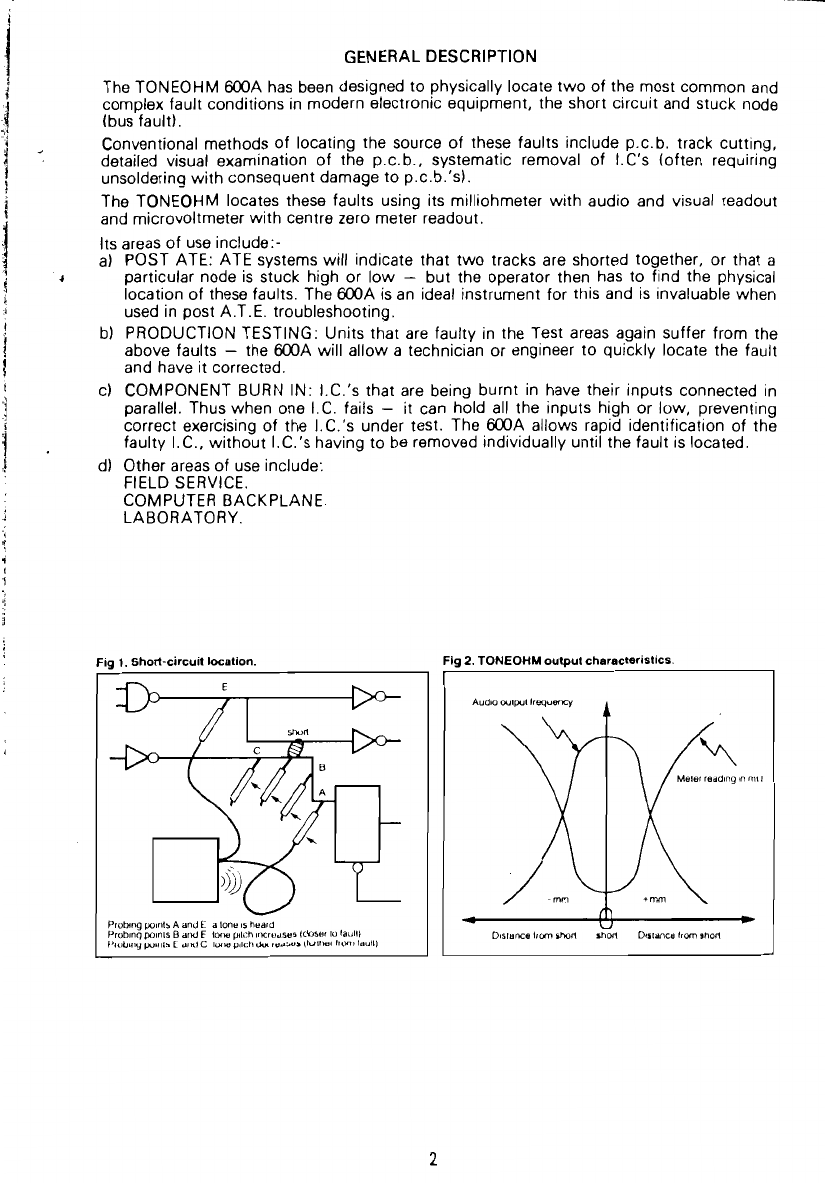
5.
Move one of the probes along the track and note the change in the pitch of the tone
(or in the meter readingl. A higher pitch (or a lower meter readingI means that the
probe is moving closer to the fault -
See
Figs. 1 &
2.lpage
2)
6.
Repeat
as
necessary to find the position
01
highest tone pitch (or minimum meter
reading), switching to the 30m
fl
range
to
give more sensitivity if required. Final
resolution can best be made by watching the meter for the null.
7.
The probe tip will
now
be
within, at most, a few
mm
of
the lault, which will
be
visually
obvious.
As
mentioned above, the
DC
O mode should be selected
if
the short occurs between
two
tracks that are coupled by capacitance le.g. power supply rails). This is to svoid the
shunting
of
the test current
by
the capacitance, which causes confusion when attempting
to trace a lault.
It should
be
noted that the maximum open circuit probe tip voltage
is
100mV, which
enslJres that semiconductor junctions are not turned on
or
damaged.
Resistance Measurements
For
maximum accuracy, the AC
o.
mode should be seleeted. Errors in the
DC
O are
primarily due
to
thermoelectrie voltages that can be generated between the probes and the
device under test.
By selecting the relevant range, eontact resistances of relays, eonneetors, etc. can be
measured.
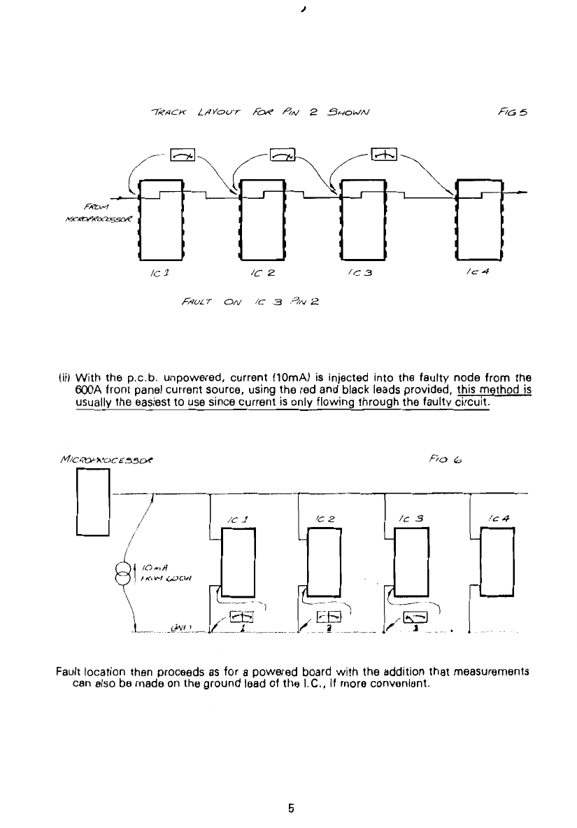
USE OF MICROVOLTMETER
Ganerai
The microvoltmeter is used to trace current
Ilow
through tracks on either powered boards
or unpowered boards stimulated
by
the current source on the 600A front panel.
This technique is valuable in locating either a panial short (e.g.
10
to 10001 or a short
which only exists when a system
is
under power.
I.C. substrate shorts, faulty eleetrolytie eapacitors (e.g. tantalum) etc. can be loeated using
this method -present methods
01
locating faults
of
this type
of
ten involve track cutting,
I.C. removal, etc.
The microvoltmeter measures the track voltage drops and in this way the faulty deviee
which
is
sinking or sourcing excessive current can be identified.
3