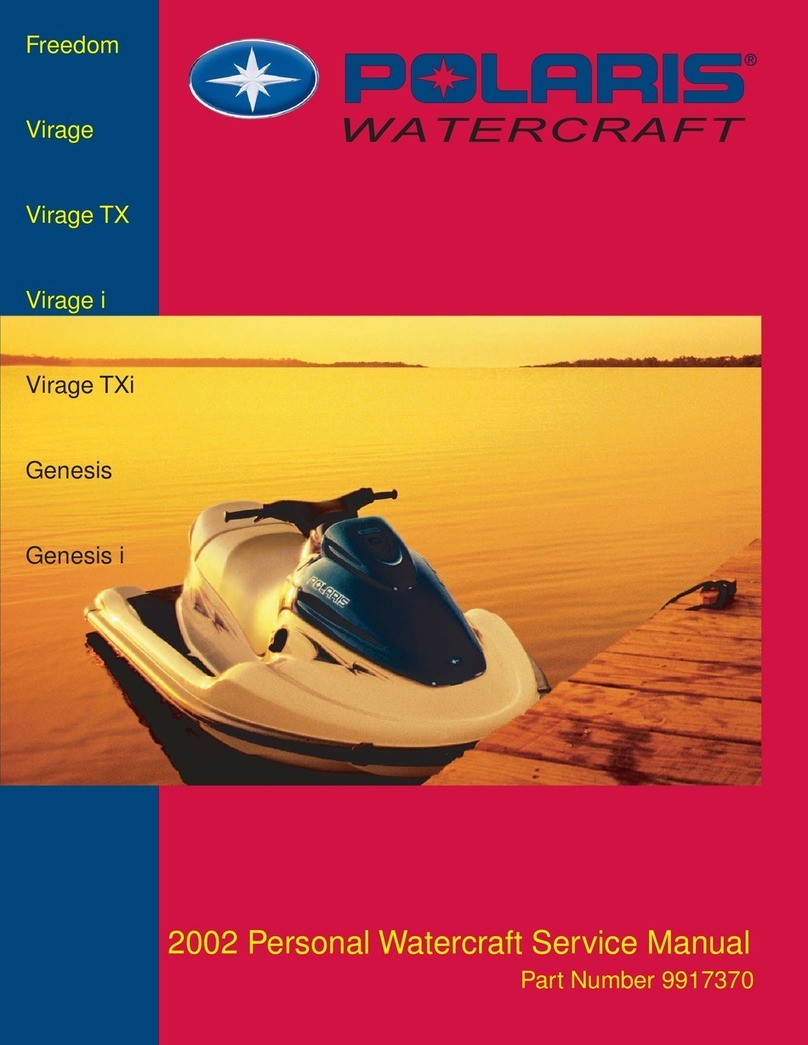
Polaris Virage TX 2000 User manual


The
Way
Out.
2000
Virage
TX,
SLX,
Pro
1200,
Genesis
FFI
™
PERSONAL
WATERCRAFT
SERVICE
MANUAL
Foreword
This
manual
is
designed
primarily
for
use
by
Polaris
personal
watercraft
service
technicians
in
a
properly
equipped
shop.
Persons
using
this
manual
should
have
a
sound
knowledge
of
mechanical
theory,
tool
use,
and
shop
procedures
in
order
to
perform
the
work
safely
and
correctly.
The
technician
should
read
the
text
and
be
familiar
with
service
procedures
before
starting
the
work.
Certain
procedures
require
the
use
of
special
tools.
Use
only
the
proper
tools,
as
specified.
Cleanliness
of
parts
and
tools
as
well
as
the
work
area
is
of
primary
impor
tance.
This
manual
includes
procedures
for
disassembly
and
reassembly,
inspection,
maintenance,
component
identifi
cation
and
unit
repair,
along
with
service
specifications
for
2000
Virage
TX,
SLX,
Genesis,
Genesis
FFI™,
and
Pro
1200
Polaris
personal
watercraft.
A
table
of
contents
is
placed
at
the
beginning
of
each
chapter
to
aid
the
user
in
locating
specific
areas
of
information.
The
alphabetic
index
at
the
end
of
the
manual
will
help
the
user
find
specific
information
quickly.
Care
is
taken
to
ensure
that
all
information
in
this
manual
was
technically
correct
at
the
time
of
publication.
How
ever,
all
materials
and
specifications
are
subject
to
change
without
notice.
Comments
or
suggestions
about
this
manual
may
be
directed
to:
Engineering
Services,
Technical
Writer,
Polaris
Sales
Inc.,
2100
Highway
55,
Medina,
MN
55340.
Technical
Training
Center
Minneapolis,
MN
55447
2000
Virage
TX,
SLX,
Pro
1200,
Genesis,
Genesis
FFI
Personal
Watercraft
Service
Manual
(PN
9916290)
Copyright2000
Polaris
Sales
Inc.,
Printed
in
U.S.A.

UNDERSTANDING
SAFETY
LABELS
AND
INSTRUCTIONS
Throughout
these
instructions,
important
information
is
brought
to
your
attention
by
the
following
symbols:
j\
The
Safety
Alert
Symbol
means
ATTENTION!
BECOME
ALERT!
YOUR
SAFETY
IS
INVOLVED!
DANGER
Failure
to
follow
DANGER
instructions
will
result
in
severe
injury
or
death
to
the
operator,
passenger,
bystander
or
person
inspecting
or
servicing
the
watercraft.
A
WARNING
Failure
to
follow
WARNING
instructions
could
result
in
severe
injury
or
death
to
the
operator,
passenger,
bystand
er
or
person
inspecting
or
servicing
the
watercraft.
CAUTION:
A CAUTION
indicates
special
precautions
that
must
be
taken
to
avoid
minor
personal
injury,
or
watercraft
or
prop
erty
damage.
NOTE:
A
NOTE
provides
key
information
to
clarify
instructions.
Polaris
acknowledges
the
following
products
mentioned
in
this
manual:
Loctite,
Registered
Trademark
of
the
Loctite
Corporation
FLEXLOC,
Registered
Trademark
of
SPS
Technologies
MityVac,
Registered
Trademark
of
Neward
Enterprises
Torx,
Trademark
of
Textron
Teflon,
Trademark
of
DuPont
Alemite,
Trademark
of
Alemite
Corporation

CHAPTER
1
GENERAL
INFORMATION
Publication
Numbers
and
FFI™
Tools
.1.1
FFI
™
Special
Tools
1.2
2000
Model
Identification
1.3
2000
Model
Specifications
1.4
-
1.5
Standard
Torque
Specifications
1.6
Decimal
Equivalents
1.7
Conversion
Tables
1.8
Tap
Drill
Charts
1.9
Glossary
of
Terms
1.10-1.11
Service
Tips
1.12

GENERAL
INFORMATION
Publication
Numbers/Paint
Codes
Watercraft
Publication
Part
Numbers
Paint
Codes
Dealer
orders
can
be
placed
through
Midwest
Industrial
Coatings
using
the
Polaris
"P"
number.
Phone
(763-942-1840).
Mix
as
directed.
Special
Tools
Polaris
Sales
Inc.
1.1
3100

GENERAL
INFORMATION
Publication
Numbers/Paint
Codes
FFI
™
Fuel
Injection
Special
Tools
2872454
-
EMM
Lap
Top
Com
Cord
2872604
-
Engine
Bumper
Tool
2872602
-
Schrader
Valve
2872456
-
EMM
Service
Power
Connector
2872621
-
Fuel
Pump
Ring
Spanner
300
1.2
Polaris
Sales
Inc.

GENERAL
INFORMATION
Model
Identification
Identification
Numbers
The
engine
I.D.
number
and
hull
I.D.
number
are
used
to
register
the
watercraft.
They
are
unique
numbers
that
distinguish
each
watercraft
from
others
of
the
same
model.
If
the
watercraft
is
ever
stolen
these
numbers
will
help
identify
it.
The
owner
should
keep
a
record
of
these
numbers
in
a
place
other
than
the
watercraft.
lumber
Identifjj^tipii;;'
■;
.;',,
•":
'■&•"
/.";
if^dtyr^l^r:"
Serial
/^/l^otith'ofV"
t
TY^rof
'-
"
^
Month
Code:
A
=
January;
B
=
February;
etc.
Year
Of
Manufacture:
9
=
1999;
0
=
2000;
etc.
Starter
Cover
Engine
I.D.
Number
(Polaris
Domestic
Engine)
Polaris
Sales
Inc.
1.3
3/00

GENERAL
INFORMATION
Model
Specifications
Polaris
reserves
the
right
to
change
specifications
at
2000
Wage
TX
2000
GeneSJS
2000
GeneSJS
FF1™
any
time
without
incurring
obligations.
*
Model
Number
W005199D
W005099D
W005098D
Dimensions/Materials/Capacities
Length
120.3"
(305.56cm)
131.1"
(330.5cm)
131.1"
(330.5cm)
Width
49.3"
(125.22cm)
49.3"
(125.22cm)
49.3"
(125.2cm)
Height
39"
(99.06cm)
40.4"
(102.6cm)
40.4"
(102.6cm)
Dry
Weight
620
(280
kg)
625
(282
kg)
625
(282
kg)
Rider
Capacity
3
person/500
lbs.
(227
kg)
4
person/600
lbs.
(272
4
person/600
lbs.
(272
kg)
kg)
Rated
Fuel
Capacity
including
reserve
....
17
U.S.
Gal
(64.4L)
17
U.S.
Gal
(64.4L)
17
U.S.
Gal
(64.4L)
Fuel
Reserve
N/A
N/A N/A
Oil
Reservoir
Capacity
-
U.S.
quarts
6.0
(5.68L)
6.0
(5.68L)
6.0
(5.68L)
Hull
Material
Sheet
Molded
Compound
Fiberglass
Reinforced
Fiberglass
Reinforced
(SMC)
Composite
(FRC)
Composite
(FRC)
Top
Deck
Material
Fiberglass
Reinforced
Fiberglass
Reinforced
Fiberglass
Reinforced
Composite (FRC)
Composite
(FRC)
Composite
(FRC)
Engine/Cooling
Engine
Model
No
W120-TCSP-02B1
W120-TCSP-02B2
W120-DFI-02B
Engine
Displacement
1165cc
1165cc
1165cc
Engine
Type
(#
Of
Cylinders)
Polaris
Marine
1200
(3)
Polaris
Marine
1200
(3)
Polaris
Marine
1200
FFI®
(3)
Bore
&
Stroke
84mm
x
70mm
84mm
x
70mm
84mm
x
70mm
Compression
Ratio
(Full
Stroke)
6.8:1
6.8:1
6.8:1
Horsepower
135
HP
@
6700
RPM
135
HP
@
6700
RPM
135
HP
@
6700
RPM
Cooling
System
Water
cooled
Water
cooled
Water
cooled
Thermostat
Open
140°F
(60°C)
140°F
(60°C)
140°F
(60°C)
Overheat
Warning
3500
Rev
Limit
@
237°F
3500
Rev
Limit
@
237°F
S.L.O.W.™/Warning
Light
(114°C)
(114°C)
Induction
Type
Case
Reed Case
Reed Case Reed
Lubrication
Oil
Injected
Oil
Injected
Oil
Injected
Oil
Type
Polaris
TC-W3,
Premium
Gold
Polaris
TC-W3,
Premium
Polaris
TC-W3,
Premium
Gold
Synthetic
or
Nature
Oil
Gold
Synthetic
or
Nature
Synthetic
or
Nature
Oil
Oil
RPM
Limiter
Operation
7200
RPM
±100
7200
RPM
±100
7200
RPM
±100
Carburetion
Carburetors
3-40mm,
Keihin
CDK
3-40mm,
Keihin
CDK
3-FICHT®
Fuel
Injectors
Fuel
Type
Regular
Unleaded
Gasoline
Regular
Unleaded
Regular
Unleaded
Gasoline
(87
Octane
or
89
if
Gasoline
(87
Octane
or
(87
Octane
or
89
if
oxygenated)
89
if
oxygenated)
oxygenated)
Idle
Speed
(In
Water)
1350±100
1350±
100 1150±50
Electrical
Magneto
Generator
Output
8.5A
/
60W
at
4500
RPM
8.5A
/
60W
at
4500
RPM
12A
/160W
at
4500
RPM
Ignition
System
Digital
CDI
Digital
CDI
FICHT®
Spark
Plug
Type
NGK
BR9ES
NGK
BR9ES
NGK
PZFR6H
Spark
Plug
Gap
(inches)
028"
(0.7mm)
.028"
(0.7mm)
.032"
(0.8mm)
Timing
Degrees
BTDC
23°±1
@3000
23°±1
@3000
N/A
15°±1
@6500
15°±1
@6500
Battery
12V19AYB16CL-B
12V19AYB16CL-B
12V19AYB16CL-B
Starting
System
Electric
Electric
Electric
Fuse
15A
resettable
circuit
breaker
15A
resettable
circuit
15A
resettable
circuit
breaker
breaker
Propulsion
Jet
Pump
Type
Single
Stage
Axial
Flow
Single
Stage
Axial
Flow
Single
Stage
Axial
Flow
Dominator
Style
Dominator
Style
Dominator
Style
ImpellerRotation
Counterclockwise
Counterclockwise
Counterclockwise
Couplingtype
Rubber
Rubber
Rubber
Bilge
Pump
Type
Electric
Electric Electric
Minimum
Water
Level
For
Jet
Pump
2
Feet
(60cm)
2
Feet
(60cm)
2
Feet
(60cm)
Pivoting
Angle
30°
30° 30°
ImpellerType
Progressive
Pitch
Slim
Hub
Progressive
Pitch
Radial
Progressive
Pitch
Radial
3
Stainless
3
Blade
NuJet
7.0
3
Blade Skat
Trak
Blade
Skat
Trak
ImpellerDiameter
5.8"
(14.73cm)
5.8"
(14.73cm)
5.8"
(14.73cm)
Reverse
System
Std
Std
Std
*MFD
/
MFI
includes:
Speedometer,
Peak
Speed,
Peak
RPM,
Tachometer,
Clock,
Hour
Meter,
Oil
Level,
Trip
Meter,
Low
Oil
Warning,
Fuel
Level,
Volts,
Low
Fuel
Warning,
Hot
Engine
Warning,
Compass.
300
1.4
Polaris
Sales
Inc.

GENERAL
INFORMATION
Model
Specifications
Polaris
reserves
the
right
to
change
specifications
at
any
time
without
incurring
obligations.
2000
SLX
9000
Pro
1900
ModelNumber
W004699D
W004999D
Dimensions/Materials/Capacities
Len9th
108.5"
(276cm)
108.5"
(276cm)
Width
47.5"
(120.7
cm)
47.5"
(120.7cm)
Height
39.5"
(100.3cm)
39.5"
(100.3cm)
Dry
Weight
565(256kg)
625(282kg)
RiderCapacity
2
person/370
lbs.
(168
kg)
2
person/370
lbs.
(168
kg)
Rated
Fuel
Capacity
including
reserve
12.5 U.S.
Gal
(47.3L)
9.8
U.S.
Gal
(37.1
L)
Fuel
Reserve
N/A N/A
Oil
Reservoir
Capacity
-
U.S.
quarts
5.0
(4.73L)
3.5
(3.31
L)
Hull
Material
Sheet
Molded
Compound
Fiberglass
Reinforced
(SMC)
Composite
(FRC)
Top
Deck
Material
Fiberglass
Reinforced
Fiberglass
Reinforced
Composite (FRC) Composite
(FRC)
Engine/Cooling
EngineModeINo
W120-TCSP-02B1
W120-TCSP-02B1
Engine
Displacement
1165cc
1165cc
Engine
Type
(#
Of
Cylinders)
Polaris
Marine
1200
(3)
Polaris
Marine
1200
(3)
Bore&Stroke
84mmx70mm
84mmx70mm
Compression
Ratio
(Full
Stroke)
6.8:1
6.8:1
Horsepower
135
HP
@
6700
RPM
135
HP
@
6700
RPM
CoolingSystem
Watercooled
Watercooled
Thermostat
Open
140°F(60°C)
140°F(60°C)
Overheat
Warning
3500
Rev
Limit
@
237°F
3500
Rev
Limit
@
237°F
(114°C)
(114°Q
Induction
Type
Case
Reed
Case Reed
Lubrication
Oil
Injected
Oil
Injected
Oil
Type
Polaris
TC-W3,
Premium
Gold
Polaris
TC-W3,
Premium
Gold
Synthetic
or
Nature
Oil
Synthetic
or
Nature
Oil
RPM
Limiter
Operation
7200
RPM
±100
7200
RPM
±100
Carburetion
Carburetors
3-40mm,
Keihin
CDK
3-40mm,
Keihin
CDK
FuelType
Regular
Unleaded
Gasoline
Regular
Unleaded
Gasoline
(87
Octane
or
89
if
(87
Octane
or
89
if
oxygenated)
.
oxygenated)
Idle
Speed
(In
Water)
135Q±100
1350±100
Electrical
Magneto
Generator Output
8.5A
/
60W
at
4500
RPM
8.5A
/
60W
at
4500
RPM
Ignition
System
DigitalCDI
DigitalCDI
SparkPlugType
NGKBR9ES
NGKBR9ES
Spark
Plug
Gap
(inches)
,
028"
(0.7mm)
.028"
(0.7mm)
TimingDegrees
BTDC
23°±1
@3000
23°±1
@3000
15°±1
@6500
15°±1
@6500
Battery
12V19A
YB16CL-B
12V19A
YB16CL-B
Starting
System
Electric
Electric
Fuse
15A
resettable
circuit
breaker
15A
resettable
circuit
breaker
Propulsion
Jet
Pump
Type
Single
Stage
Axial
Flow
Single
Stage
Axial
Flow
Dominator
Style
Dominator
Style
ImpellerRotation
Counterclockwise
Counterclockwise
Couplingtype
Rubber
Rubber
Bilge
Pump
Type
Electric
Electric
Minimum
Water
Level
For
Jet
Pump
2
Feet
(60cm)
2
Feet
(60cm)
PivotingAngle
30° 30°
Impeller
Type
Progressive
Pitch
Slim
Hub
Progressive
Pitch
Radial
Stainless
3 Blade
NuJet
7.0
3
Blade
NuJet
7.0
ImpellerDiameter
5.8"
(14.73cm)
5.8"
(14.73cm)
Reverse
System
N/A
N/A
*MFD/
MFI
includes:
Speedometer,
Peak
Speed,
Peak
RPM,
Tachometer,
Clock,
Hour
Meter,
Oil
Level,
Trip
Meter,
Low
Oil
Warning,
Fuel
Level,
Volts,
Low
Fuel
Warning,
Hot
Engine
Warning,
Compass.
(Some
models
do
not
have
all
features.)
Polaris
Sales
Inc.
1.5
3/00

GENERAL
INFORMATION
Standard
Torque
Specifications
The
following
torque
specifications
are
to
be
used
as
a
general
guideline.
Use
standard
torque
values
for
the
appropriate
size
fastener
when
torque
values
are
not
specified.
Always
consult
the
specific
manual
section
for
torque
values
of
fasteners
and
use
of
locking
agent.
To
convert
in.
lbs.
to
ft.
lbs.
divide
by 12
To
convert
ft.
lbs.
to
Nm
multiply foot
pounds
by
1.356.
To
convert
Nm
to
ft.
lbs.
multiply
Nm
by
.7376.
3/00
1.6
Polaris
Sales
Inc.

GENERAL
INFORMATION
Decimal
Equivalents
1/64
0156
1/32
0312
1
mm
=
.0394"
3/64
0469
1/16
0625
5/64
0781
2
mm
=
.0787"
3/32
0938
7/64
1094
3
mm
=
.1181"
1/8
1250
9/64
1406
5/32
1563
4
mm
=
.1575"
11/64
1719
3/16
1875
5
mm
=
.1969"
13/64
2031
7/32
2188
15/64
2344
6
mm
=
.2362"
1/4
25
17/64
2656
7
mm
=
.2756"
9/32
2813
19/64
2969
5/16
3125
8
mm
=
.3150"
21/64
3281
11/32
3438
9
mm
=
.3543"
23/64
3594
3/8
375
25/64
3906
10
mm
=
.3937"
13/32
4063
27/64
4219
11
mm
=
.4331"
7/16
4375
29/64
4531
15/32
4688
12
mm
=
.4724"
31/64
4844
1/2
5
13
mm
=
.5118
33/64
5156
17/32
5313
35/64
5469
14
mm
=
.5512"
9/16
5625
37/64
5781
15
mm
=
.5906"
19/32
5938
39/64
6094
5/8
625
16
mm
=
.6299"
41/64
6406
21/32
6563
17
mm
=
.6693"
43/64
6719
11/16
6875
45/64
7031 18
mm
=
.7087"
23/32
7188
47/64
7344
19
mm
=
.7480"
3/4
75
49/64
7656
25/32
7813
20
mm
=
.7874"
51/64
7969
13/16
8125
21
mm
=
.8268"
53/64
8281
27/32
8438
55/64
8594
22
mm
=
.8661"
7/8
875
57/64
8906
23
mm
=
.9055"
29/32
9063
59/64
9219
15/16
9375
24
mm
=
.9449"
61/64
9531
31/32
9688
25
mm
=
.9843
63/64
9844
1
1.0
Polaris
Sales
Inc.
^~y
3/00

GENERAL
INFORMATION
Conversion
Table
°C
to
°F:
9
(°C
+
40)
-
5
-
40
=
°F
°F
to
°C:
5
(°F
+
40)
+
9
-
40
=
°C
300
1.8
Polaris
Sales
Inc.

GENERAL
INFORMATION
Tap
Drill
Charts
SAE
Tap
Drill
Sizes
Metric
Tap
Drill
Sizes
Polaris
Sales
Inc.
1.9
3/00

GENERAL
INFORMATION
Glossary
Of
Terms
ABDC:
After
bottom
dead
center.
ATDC:
After
top
dead
center.
ACV:
Alternating
current
voltage.
Alternator:
Electrical
generator producing
voltage
alternating
current.
BBDC:
Before
bottom
dead
center.
BDC:
Bottom
dead
center.
BTDC:
Before
top
dead
center.
Bow:
The
front
of
a
watercraft
C:
Celsius
CC:
Cubic
centimeters.
CDI:
Capacitor
discharge
ignition.
Ignition
system
which
stores
voltage
generated
by
the
stator
plate
exciter
coil
in
a
capacitor
or
condenser
(in
CDI
box).
At
the
proper
moment
a
voltage
generated
by
the
stator
plate
pulser
coil
closes
an
electronic
switch
(thyristor)
in
the
CDI
box
and
allows
the
voltage
in
the
capacitor
to
discharge
into
the
primary
windings
of
the
ignition
coil.
Cl:
Cubic
inches.
Condenser/Capacitor:
A
storage
reservoir
for
electricity,
used
in
both
E.T.
and
CDI
systems.
Crankshaft
Run-Out:
Run-out
or
"bend"
of
crankshaft
measured
with
a
dial
indicator
while
crankshaft
is
supported
between
centers
on
V
blocks
or
resting
in
lower
half
of
crankcase.
Measure
at
various
points
especially
at
the
PTO
end.
DCV:
Direct
current
voltage.
Detonation:
The
spontaneous
ignition
of
the
unburned
fuel/air
mixture
after
normal
ignition
spark
occurs.
Piston
looks
"hammered"
through,
rough
appearance
around
hole.
Possible
causes:
1)
Compression
ratio
too
high
for
the
fuel
octane;
2)
low
octane
fuel;
3)
over-advanced
ignition
timing.
Dial
Bore
Gauge:
A
cylinder
measuring
instrument
which
uses
a
dial
indicator.
Good
for
showing
taper
and
out-of-round
in
the
cylinder
bore.
End
Seals:
Rubber
seals
at
each end
of
the
crankshaft.
F:
Fahrenheit
ft.:
Foot/feet.
Foot
Pound:
Ft.
Ib.
A
force
of
one
pound
at
the
end
of
a
lever
one
foot
in
length,
applied
in
a
rotational
direction.
g:
Gram.
Unit
of
weight
in
the
metric
system.
There
are
28
grams
in
one
ounce.
gal.:
Gallon.
Head Volume
(Uninstalled):
Cylinder
head
capacity
in
cc,
head
removed
from
engine
with
spark
plug
installed.
High
Tension
Lead:
The
heavy
insulated
wire
which
carries
the
high
secondary
voltage
from
the
coil
to
the
spark
plug.
Holed
Piston:
Piston
in
which
a
hole
has
formed
on
the
dome.
Possible
causes:
1)
detonation;
2)
pre-ignition.
HP:
Horsepower.
ID:
Inside
diameter.
Ignition
Coil:
A
type
of
transformer
which
increases
voltage
in
the
primary
windings
(approx.
200V)
to
a
higher
voltage
in
the
secondary
windings
(approx.
14KV
-
32KV)
through
induction.
Secondary
voltage
must
be
high
enough
to
ionize
the
air
gap
at
the
spark
plug.
Ignition
Generating
Coil:
Exciter
coil,
primary
charge
coil.
Stator
plate
coil
which
generates
primary
ignition
voltage.
in.:
Inch/inches.
kg/cm
:
Kilograms
per
square
centimeter.
Kg-m:
Kilogram
meters.
Km:
Kilometer.
Kilogram
meter:
A
force
of
one
kilogram
at
the
end
of
a
lever
one
meter
in
length,
applied
in
a
rotational
direction.
300
1.10
Polaris
Sales
Inc.

GENERAL
INFORMATION
Glossary
Of
Terms
I
or
Itr:
Liter.
One
liter
=
1.0567
U.S.
quarts.
lbs/in
:
Pounds
per
square
inch.
Inch
Pound:
In.
Ib.
12
in.
lbs.
=
1
ft.
Ib.
Left
Side:
The
left
hand
side
of
the
vehicle.
Referred
to
based
on
normal
operating
position
of
the
driver.
m:
Meter/meters.
Mag:
Magneto.
Magnetic
Induction:
As
a
conductor
(coil)
is
moved
through
a
magnetic
field,
a
voltage
will
be
generated
in
the
windings.
This
is
how
mechanical
energy
is
converted
to
electrical
energy
in
the
lighting
coil,
ignition
generating
coils
and
trigger
coil.
mi.:
Mile/miles.
mm:
Millimeter.
Unit
of
length
in
the
metric
system.
1mm
=
.040".
N-m:
Newton
meters.
OD:
Outside
diameter.
Ohm:
The
unit
of
electrical
resistance
opposing
current
flow.
Open
Circuit:
An
electrical
circuit
which
is
incomplete,
(e.g.
poor
connections
or
broken
wire
preventing
the
flow
of
current).
oz.:
Ounce/ounces.
Piston
Clearance:
Total
distance
between
piston
and
cylinder
wall.
Piston
Erosion:
Piston
dome
melts.
Usually
occurs
at
the
exhaust
port
area.
Possible
causes:
1)
lean
fuel/air
mixture;
2)
improper
spark
plug
heat
range.
Pre-lgnition:
A
problem
in
combustion
where
the
fuel/air
mixture
is
ignited
before
normal
spark
ignition.
Piston
looks
melted
at
area
of
damage.
Possible
causes:
1)
Spark
plug
heat
range
incorrect
(too
hot)
2)
spark
plug
not
properly
torqued;
3)
"glowing"
piece
of
head
gasket,
metal
burr
or
carbon
in
the
combustion
chamber;
4)
lean
fuel/air
mixture.
Primary
Circuit:
This
circuit
is
responsible
forthe
voltage
build
up
in
the
GDI
capacitor.
In
a
CDI
system
the
parts
include
the
exciter
coil,
the
trigger
coil,
the
wires
from
stator
plate
to
CDI
box
and
to
the
ignition
coil
primary
windings.
psi.:
Pounds
per
square
inch.
pts:
Pint/pints
PTO:
Power
take
off.
qt.:
Quart/quarts.
RPM:
Revolutions
per
minute.
Resistance:
In
the
mechanical
sense,
friction
or
load.
In
the
electrical
sense,
ohms.
Both
result
in
energy
conversion
to
heat.
Right
Side:
The
right
hand
side
of
the
vehicle.
Always
Referred
to
based
on
normal
operating
position
of
the
rider.
Running
Time:
Ignition
timing
at
specified
RPM.
Secondary
Circuit:
This
circuit
consists
of
the
ignition
coil
secondary
windings,
high
tension
wire
and
ground
through
the
spark
plug
air
gap.
Seized
Piston:
Galling
of
the
sides
of
a
piston.
Usually
there
is
a
transfer
of
aluminum
from
the
piston
onto
the
cylinder
wall.
Possible
causes:
1)
improper
lubrication;
2)
excessive
temperatures;
3)
insufficient
piston
clearance;
4)
stuck
piston
rings.
Short
Circuit:
An
electrical
circuit
which
is
completed
before
the
current
reaches
the
intended
component,
(e.g.
a
bare
wire
touching
a
grounded
component.
Spark
Plug
Reach:
Length
of
threaded
portion
of
spark
plug.
Polaris
uses
3/4"
(2
cm)
reach
plugs.
Static
Timing:
Ignition
timing
when
engine
is
at
zero
RPM.
Stator
Plate:
The
plate
mounted
under
the
flywheel
supporting
the
primary
ignition
components
and
lighting
coil.
TDC:
Top
dead
center.
Piston's
most
outward
travel
from
crankshaft.
Trigger
Coil:
Pulser
coil.
Generates
the
voltage
for
triggering
(closing)
the
thyristor
and
timing
the
spark
in
CDI
systems.
Small
coil
mounted
at
the top
of
the
stator
plate
next
to
the
ignition
generating
coil.
Voltage
Regulator:
An
electrical
device
which
prevents
overcharging
of
the
battery
or
overloading
of
electrical
components
as
engine
RPM
increases.
Polaris
Sales
Inc.
-|
-|-|
"
3j0q

GENERAL
INFORMATION
Service
Tips
In
order
to
perform
service
work
efficiently
and
to
prevent
costly
errors,
the
technician
should
begin
by
reading
the
text
in
this
manual
to
become
familiar
with
procedures
before
beginning.
Pictures
and
illustrations
have
been
included
with
the
text
as
an
aid.
Notes,
cautions
and
warnings
have
also
been
included
for
clarification
of
text
and
safety
concerns.
However,
a
knowledge
of
mechanical
theory,
tool
use,
and
shop
procedures
is
necessary
to
perform
the
service
work
safely
and
satisfactorily.
Use
only
genuine
Polaris
service
parts.
nS
Cleanliness
of
parts
and
tools
as
well
as
the
work
area
is
of
primary
importance.
Dirt
and
foreign
matter
will
act
as
an
abrasive
and
cause
damage
to
precision
parts.
Clean
the
vehicle
before
beginning
service.
Clean
new
parts
before
installing.
As
Watch
for
sharp
edges
which
can
cause
personal
injury.
Protect
hands
with
gloves
when
working
with
sharp
components.
A±
If
difficulty
is
encountered
in
removing
or
installing
a
component,
look
to
see
if
a
cause
for
the
difficulty
can be
found.
If
it
is
necessary
to
tap
the
part
into
place,
use
a
soft
face
hammer
and
tap
lightly.
nS
Some
of
the
fasteners
were
installed
with
locking
agents.
Use
of
impact
drivers
or
wrenches
will
help
avoid
damage
to
fasteners.
/K
Always
follow
torque
specifications
as
outlined
throughout
this
manual.
Incorrect
torquing
may
lead
to
serious
machine
damage
or,
as
in
the
case
of
steering
components,
can
result
in
injury
or
death
for
the
rider(s).
nS
If
a
torquing
sequence
is
indicated
for
nuts,
bolts
or
screws,
start
all
fasteners
in
their
holes
and hand
tighten.
Then,
following
the
method
and
sequence
indicated
in
this
manual,
tighten
evenly
to
the
specified
torque
value.
When
removing
nuts,
bolts
or
screws
from
a
part
with
several
fasteners,
loosen
them
all
about
1/4
turn
before
removing
them.
^
If
the
condition
of
any
gasket
or
O-Ring
is
in
question,
replace
it
with
a
new
one.
Be
sure
the
mating
surfaces
around
the
gasket
are
clean
and
smooth
in
order
to
avoid
leaks.
iK
Some
procedures
will
require
removal
of
retaining
rings
or
clips.
Because
removal
weakens
and
deforms
these
parts,
they
should
always
be
replaced
with
new
parts.
When
installing
new
retaining
rings
and
clips
use
care
not
to
expand
or
compress
them
beyond
what
is
required
for
installation.
nS
Because
removal
damages
seals,
replace
any
oil
or
grease
seals
removed
with
new
parts.
A
suitable
driver
should
be
used
when
installing
a
new
seal
to
prevent
distortion
or
damage.
/K
Polaris
recommends
the
use
of
Polaris
lubricants
and
greases,
which
have
been
specially
formulated
for
the
top
performance
and
best
protection
of
our
machines.
In
some
applications,
such
as
the
engine,
warranty
coverage
may
become
void
if
other
brands
are
substituted.
/K
Grease
should
be
cleaned
from
parts
and
fresh
grease
applied
before
reassembly
of
components.
Deteriorating
grease
loses
lubricity
and
may
contain
abrasive
foreign
matter.
lK
Whenever
installing
batteries,
care
should
be
taken
to
avoid
the
possibility
of
explosion
resulting
in
serious
burns.
Always
connect
the
positive
(red)
cable
first
and
the
negative
(black)
cable
last.
When
working
with
batteries,
always
wear
safety
glasses
or
a
face
shield
and
protective
gloves.
Battery
electrolyte
contains
sulfuric
acid
and
is
poisonous!
Serious
burns
can
result
from
contact
with
the
skin,
eyes
or
clothing.
ANTIDOTE:
External
-
Flush
with
water.
Internal
-
Drink
large
quantities
of
water
or
milk.
Follow
with
milk
of
magnesia,
beaten
egg,
or
vegetable
oil.
Call
physician
immediately.
Eyes
-
Flush
with
water
for
15
minutes
and
get
prompt
medical
attention.
300
1.12
Polaris
Sales
Inc.

CHAPTER
2
MAINTENANCE/TUNE
UP
Maintenance
Schedule
2.1
-2.2
Recommended
Lubricants
/
Products
2.3
Lubrication
of
Components
2.4-2.7
Electrical
Maintenance
2.8-2.11
Engine
Maintenance
2.12
-
2.18
Cable
Adjustments
2.19
-
2.25
Fuel
System
Maintenance
2.25
-
2.29
Cooling
System
Maintenance
2.30
-
2.31
Storage
2.30
-
2.32
Cleaning
2.33
Bilge
System
2.34
MFD
/
MFI
Gauges
2.35
Submerged
Engine
2.36
Pump
/
Impeller
Maintenance
2.37
Hull
/
Deck
Maintenance
2.38
■
2.39
Troubleshooting
2.40
-
2.45

MAINTENANCE/TUNE
UP
Maintenance
Schedule
Periodic
Maintenance
Schedule
NOTE:
Maintenance
intervals
are
based
upon
average
operating
conditions.
Watercraft
operated
in
saltwater
require
daily
corrosion
protection
and
engine
flushing,
and
more
frequent
maintenance
and
lubrication.
*
Perform
every
15
hrs.
or
one
month
when
operated
in
salt
water.
**Perform
daily
when
operated
in
salt
water.
***Bonded
rubber
couplers-Pre-Season
(Annually),
100
hrs,
or
when
pump
is
disassembled
for
maintenance.
****Genesis
FFI™
water
separating
filter
requires
no
periodic
maintenance.
CD
Replace
pop-off
valve,
spring,
and
seals
every
100
hours
only
(not
every
6
months).
[2]
Replace
water
separator
filter
element
and
o-ring
every
100
hours
only
(not
every
6
months).
Q
Replace
inlet
and
outlet
hoses
and
clamps
every
100
hours
only.
Polaris
Sales
Inc.
2.1
3/00

MAINTENANCE/TUNE
UP
Maintenance
Schedule
Periodic
Maintenance
Schedule
NOTE:
Maintenance
intervals
are
based
upon
average
operating
conditions.
Watercraft
operated
in
saltwater
require
daily
corrosion
protection
and
engine
flushing,
and
more
frequent
maintenance
and
lubrication.
Fogging
kits
should
be
added
to
all
Polaris
watercraft.
The
engine
should
be
fogged
if
the
PWC
will
not
be used
for
more
than
48
hours.
*
Perform
every
15
hrs.
or
one
month
when
operated
in
salt
water.
**Perform
daily
when
operated
in
salt
water.
***Bonded
rubber
couplers-Pre-Season
(Annually),
100
hrs,
or
when
pump
is
disassembled
for
maintenance.
Q]
Replace
pop-off
valve,
spring,
and
seals
EJReplace
water
separator
filter
element
and
o-ring
KEY
l=lnspect,
adjust,
service,
or
replace
if
necessary
A=Adjust
L=Lubricate
with
recommended
lubricant
C=Clean
R=Replace
item
After
washing
the
engine
compartment
of
the
watercraft,
protect
the
metal
components
with
a
heavy
duty
siiicone
based
spray
lube
or
other
non-flammable
metal
protectant.
Do
not
use
flammable
sprays
or
protectants
in
the
engine
compartment.
Do
not
use
petroleum
based
protectants
or
lubricants
in
the
engine
compartment,
as
most
are
flammable
and
also
may
deteriorate
rubber
components.
Engine
Break-In
Carbureted
Models:
Breaking
in
a
new
engine
is
critical!
All
Polaris
watercraft
utilize
oil
injection,
however,you
must
add
oil
to
the
fuel
in
the
fuel
tank
for
the
first
tank
of
fuel
only.
Mix
Polaris
Premium
2
cycle
oil,
or
Polaris
Premium
Gold
Synthetic
oil
with
the
first
tank
of
fuel
at
a
40:1
ratio.
After
the
first
tank
of
fuel/oil
mixture
is
gone,
fill
fuel
tank
with
recommended
octane
fuel
only.
After
any
repair
where
pistons,
piston
rings,
cylinders,
or
crank
shafts
are
replaced,
the
first
tank
of
fuel
must
be
mixed
with
oil
in
the
above
fashion.
FF1™
Models:
It
is
not
necessary
to
mix
the
first
tank
of
fuel
with
oil.
The
FFI
™ system
utilizes
a
fuel
injector
for
each
cylinder,
therefore,
fuel
by
itself
does
not
enter
any
part
of
the
crankcase.
Oil
is
injected
into
the
crank-
case
via
an
oil
pump
and
check
valves
on
the
throttle
bodies.
The
extra
oil
that
would
be
added
to
the
fuel
tank
would
be
passed
through
the
fuel
injectors
and
would
not
reach
internal
engine
parts.
ss
**
-.
Si
^--J--^
%>vrt^
ji
N
<-M"*i^
t^'V/'Jifi
iV^
'"^--
"■
'
*■'
■'■"
^
w^
SSSi
3/00
2.2
Polaris
Sales
Inc.

MAINTENANCE/TUNE
UP
Recommended
Lubricants/Maintenance
Products
As
with
all
watercraft,
proper
lubrication
and
corrosion
protection
are
necessary
to
maintain
performance
and
en
sure
years
of
trouble
free
service.
Use
the
recommended
lubricant
for
each
component
as
indicated
in
the
chart
below.
Polaris
Sales
Inc.
2.3
3/00
This manual suits for next models
9
Table of contents
Other Polaris Boat manuals

Polaris
Polaris WATERCRAFT Freedom User manual

Polaris
Polaris 2003 Genesis i Guide

Polaris
Polaris SLX W004699D User manual

Polaris
Polaris VIRAGE W005197D User manual

Polaris
Polaris msx 110 Guide

Polaris
Polaris SLT780 1996 Guide

Polaris
Polaris msx 110 User manual
Polaris
Polaris Freedom 2002 Guide

Polaris
Polaris 2003 MSX User manual
Popular Boat manuals by other brands

Sea Eagle
Sea Eagle 300x Instruction & owner's manual

Boston Whaler
Boston Whaler Boston Whaler Operating and maintenance manual

CHILDHOME
CHILDHOME CHILD WOOD WOODROCK CWWRO Series Assembly instructions

Baja
Baja Performance 245 owner's manual

Topper
Topper TOPAZ OMEGA Rigging instructions

Sea Ray
Sea Ray 310 Sundancer Specific information