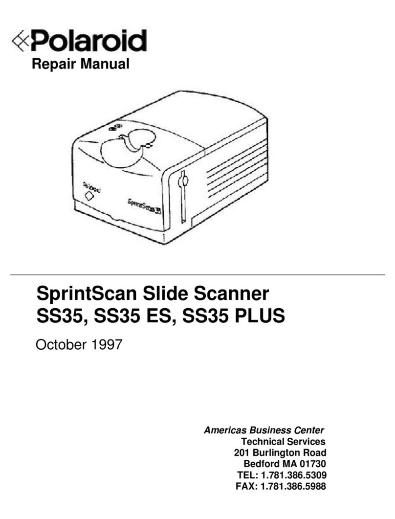
Polaroid SS35 LE Operating instructions

Repair Manual
Americas Business Center
Technical Services
201 Burlington Road
Bedford MA 01730
TEL: 1.781.386.5309
FAX: 1.781.386.5988
SprintScan Slide Scanner
SS35 LE
September 1996

2
SprintScan 35LE Service Manual Table of Contents
Table of Contents
Page
1 - Functional Description ................................................................................ 4
Photoelectric Converter .............................................................................. 4
Analog-to-Digital Converter ........................................................................ 5
Data Transfer Module ................................................................................. 6
Command and Message Transfer............................................................... 6
2 - Disassembly ................................................................................................. 7
Removing Scanner Upper Housing............................................................. 7
Removing Scanner Lamp............................................................................ 10
Removing Main PC Board........................................................................... 11
Removing Chassis Assembly (with Filter/Motor)......................................... 13
Removing Power Supply............................................................................. 15
Removing Scanner Fuses........................................................................... 16
Replacing System Fuse............................................................................ 16
Replacing Power Supply Fuse ................................................................. 17
Removing AC Inverter................................................................................. 18
3 - Troubleshooting........................................................................................... 19
Electrical Problems ..................................................................................... 19
Checking Power Supply Output Voltages................................................. 23
Checking for Short Circuit on Main PC Board.......................................... 24
Checking Scanner Lamp .......................................................................... 25
Checking CCD Module............................................................................. 26
Checking for Main PC Board Failure........................................................ 28
Checking SCSI Port.................................................................................. 28
Checking Filter Stepper Motor Malfunction.............................................. 29
Checking Carriage Stepper Motor Malfunction ........................................ 30
Photo Sensor Error ................................................................................ 30
Stepper Motor Malfunction..................................................................... 31
Optical Problems......................................................................................... 32
Checking Focus and Alignment................................................................ 32
Correcting Focus and Alignment Problems.............................................. 35
Noise Problems........................................................................................... 36
3
SprintScan 35LE Service Manual Table of contents
List of Illustrations
Figure Page
1-1 Simplified Block Diagram....................................................................... 4
1-2 Photoelectric Converter......................................................................... 4
1-3 CCD Output Waveform .......................................................................... 5
1-4 CCD Output Signal After Bias Restored................................................ 5
2-1 Removing Lamp Lid............................................................................... 7
2-2 Removing Scanner Lamp ...................................................................... 8
2-3 Removing Upper Housing...................................................................... 8
2-4 Installing Upper Housing ....................................................................... 9
2-5 Replacing Scanner Lamp ...................................................................... 10
2-6 Removing Main PC Board ..................................................................... 11
2-7 Main PC Board ...................................................................................... 11
2-8 Major Component Numbers ................................................................... 12
2-9 Chassis Assembly Mounting Screws..................................................... 13
2-10 Filter/Motor Assembly Alignment........................................................... 14
2-11 Removing Power Supply........................................................................ 15
2-12 Replacing System Fuse......................................................................... 16
2-13 Replacing Power Supply Fuse............................................................... 17
2-14 Replacing AC Inverter ........................................................................... 18
3-1 Simplified Troubleshooting Diagram...................................................... 19
3-2 Power Supply Output Connector J6 Pin Assignment............................. 23
3-3 Pre/Post Processing CCD Output Waveforms....................................... 26
3-4 Pin Assignment for Connector J7 .......................................................... 27
3-5 Preprocessing CCD Output Waveform at J7, Pin 16............................. 27
3-6 Post-processing CCD Output Waveform at TP2 ................................... 28
3-7 CCD Response (Correct Focus and Alignment).................................... 33
3-8 CCD Response (Incorrect Focus and Alignment).................................. 34
List of Tables
Table Page
3-1 Troubleshooting Guide .......................................................................... 20

SprintScan 35LE Service Manual Functional Description
4
1 - Functional Description
TheSprintScan35LE(Figure1-1)isahigh-speed,high-resolutionslidescannerthat
convertspicturesonslideintobinarycodeforfurtherprocessingbyahostcomputer.
Figure 1-1. Simplified block diagram
Theimageisfirstconvertedintoanalogsignalswhichvaryinmagnitudeaccordingto
shadingintheoriginaldocument. Inthesecondphase,theanalogsignalsaredigitized.
Theresultingbinarycodesstoredinavideobufferandtransmittedvia the SCSI bus to the
host. Individualfunctionalblocksaredescribedinthefollowingsections.
Photoelectric Converter
Thephotoelectricconverter(Figure1-2)consistsofalightsource,lens,andlinear-array
CCDwithassociateddrivingcircuitry.
Figure 1-2. Photoelectric converter (slide view)
Image Photo-
Electric
Converter
Analog-
To-Digital
Converter
Data
Transfer
Module Host
Transparent
CCD
Lens Filter
Lamp

SprintScan 35LE Service Manual Functional Description
5
AsshowninFigure1-2,lightfromthelamppassesthroughtheslideontothesurfaceofthe
CCD,whichgenerateselectricalsignalsproportionaltotheintensityofthelight. TheCCD
isoperatedso thatthemagnitudeoftheelectricalsignalislinearlyproportional tothe
intensity of received light. Since the CCD scans one line at a time, a stepping motor is
used to move the slide so the CCD can scan the entire slide.
Analog-to-Digital Converter
OutputfromtheCCDisfed to thismodule,andmostofthescanned-data processing is
doneinthisstage.ThewaveformoutputbytheCCDisshowninFigure1-3,wherethe
magnitudeoftheoutputsignalwithrespecttothebiasvoltageisafunctionoftheintensity
ofthelightincidentupon the CCD.
Figure 1-3. CCD output waveform
Sinceoutput-signalbiasvoltagevariesfordifferentCCDs,andoutputnotchesdegrade
systemresponse,theoutput-signalbiasvoltageisfirstrestoredtoground,andthena
sample-and-holdoperationiscarriedouttoeliminateoutputnotches.Theresultant
waveformisshowninFigure1-4.
Figure 1-4. CCD output signal after bias restored
Output Notch
Valid Data
Vbias
Vaild Data
Vbias = Ground

SprintScan 35LE Service Manual Functional Description
6
From Figure 1-4 it can be seen that the CCD signal is smoother and the bias voltage is
independentofCCDcharacteristics.
Thereferencevoltageisderivedthroughaprocesscalled calibration. Becauseofthe
characteristicsoflampandlens,themagnitudeoftheCCD’soutputislowertowardthe
beginningandendofascanlinethan it is in the centralportion,evenwhentheinputslide
isuniformlywhite. Calibrationisusedtocompensateforthisspatialvariation.
Data Transfer Modules
Inthethirdphaseofscanneroperation,thescanneddataaretransferredtothevideoping-
pongbuffer. Thenthe data in the buffer are moved out to thehostcomputerviatheSCSI
bus.
Command and Message Transfer
Thescanneracceptscommandsfrom,andsendsmessagesto,thehostcomputerviathe
SCSIbus. Allcommandsand messages aretransmittedintheform of recordswithafixed
syntax. Commandformatandrecordsyntaxaredescribeddetailin theSprintScan35LE
CommandSetManual.

SprintScan 35LE Service Manual Disassembly
7
2 - Disassembly
This section of the Service Manual describes SprintScan 35LE disassembly
procedures. Before carrying out any of the procedures described in this section, make
sure that the scanner has been turned off and the power cord has been disconnected.
To prevent any chance of electric shock, the SprintScan 35LE housing should only be
opened by qualified service personnel, and only after the scanner has been
disconnected from the power source.
Care should be taken throughout all disassembly and reassemble procedures never to
smudge or soil the lens or either mirror.
Removing Scanner Upper Housing
1. Turn off the power and disconnect the power cord.
2. Removethescannerlamplid(Figure2-1).
Figure 2-1. Removing lamp lid

SprintScan 35LE Service Manual Disassembly
8
3. Removethescannerlamp(Figure2-2).
Figure 2-2. Removing scanner lamp
4. Removethefour(4)screws(Figure2-3)securingthebottomcase,thenremovethe
upperhousing. Thelatchofthebasehousingmayfalloff.
Figure 2-3. Removing upper housing

SprintScan 35LE Service Manual Disassembly
9
To put the scanner upper housing back on, follow these steps:
5. Put the latch seated into its position, close the upper housing, align the tabs on the
bottomoftheupperhousingwiththeslotsatthefrontandrearofthebottomcase,
snapthehousingback on(Figure2-4).
6. Then retighten the four (4) screws.
Figure 2-4. Installing upper housing

SprintScan 35LE Service Manual Disassembly
10
Removing Scanner Lamp
Notes: • The scanner lamp should be replaced if it begins to flicker or dim,
or if the READY indicator fails to come on and a lamp failure report is
returned when the N or S command is sent.
• Only use replacement lamps obtained from Polaroid or an authorized
distributor. Use of any other lamp may adversely affect scanning
results.
1. Turn off the power and disconnect the power cord.
2. Removethescannerlamplid(Figure2-5).
3. Replace the scanner lamp with a new one.
Figure 2-5. Removing scanner lamp
Scanning Lamp Specifications
Microtek Part Number 570-22-000004
Length
Diameter
Power Consumption
5.9" (149.9 mm)
0.6" (15.5 mm)
4W
Polaroid 1E6624A

SprintScan 35LE Service Manual Disassembly
11
Removing Main PC Board
1. Turn off the power and disconnect the power cord.
2. Remove the upper housing.
3. Removethefour(4)screwssecuringthemainPCboard(Figure2-6).
Figure 2-6. Removing main PC board
4. DisconnectallconnectorsandthenliftoutthemainPCboard(Figure2-7).
Figure 2-7. Main PC board

SprintScan 35LE Service Manual Disassembly
12
5. MajorcomponentnumbersareshowninFigure2-8.
Figure 2-8. Major component numbers
J5 J6
J7
J3
J1
J2
To Carriage Motor
To Filter Motor
M-922
To Fan
SCSI Interface
SCSI ID SW1
To Voltage
To Power Supply
TP4
TP3
TP2
TP1
CCD Counector

SprintScan 35LE Service Manual Disassembly
13
Removing Chassis Assembly (with Filter\Motor)
1. Turn off the power and disconnect the power cord.
2. Remove the upper housing.
3. Remove the main PC board.
4. Removethethree(3)screws(Figure2-9)securingthechassisassembly.
5. Lift out the chassis assembly.
Figure 2-9. Chassis assembly mounting screws
6. Remove the filter mount setscrew to remove the filter/motor assembly
(Figure2-10) fromthechassisassembly.
Note: Always refer to the Filter/Motor Assembly Alignment procedure in Section 3
ofthisServiceManual whenreinstallingchassisassembly
Set screw, 1/8"

SprintScan 35LE Service Manual Disassembly
14
Figure 2-10. Filter assembly alignment
Photo sensor

SprintScan 35LE Service Manual Disassembly
15
RemovingPower Supply
1. Turn off the power and disconnect the power cord.
2. Remove the upper housing.
3. Remove the main PC board.
4. Remove the chassis assembly.
5. Removethefour(4)screwssecuringthepowersupply(Figure2-11)tothe
bottom case.
Figure 2-11. Removing power supply
6. Remove the power supply.
7. Once the power supply is fixed, replace it on the bottom case and tighten the
four (4) securing screws.

SprintScan 35LE Service Manual Disassembly
16
Removing Scanner Fuses
Notes: • If the POWER indicator, READY indicator and scanner lamp all fail to
light up when the SprintScan 35LE scanner is turned on, first make sure
that power exists at the source.
•If power availability can be confirmed and the scanner’s lights still fail to
come on, check the fuse.
There are two fuses installed in the SprintScan 35LE scanner: one is located at the rear
of the scanner and the other is located in the power supply.
Replacing System Fuse
1. Turn off the power and disconnect the power cord.
2. Useaflatscrewdrivertoleveroverthefuselid(Figure2-12).
Figure 2-12. Replacing system fuse
3. Replace the fuse. (A spare fuse is located close to the rear side.)
Fuse Specifications (At the rear)
UL and CSA
(U.S.A) Bel 5MF 1.6, Buss GMA-1 6/10,
Little 23501.6A
TUV GS
(Europe)
Bel 5SF 1.6, Eska 520.600,
Little 2170.16, Olvis EA,
Schurter SP001.1006
Fuse

SprintScan 35LE Service Manual Disassembly
17
Replacing Power Supply Fuse
1. Turn off the power and disconnect the power cord.
2. Remove the scanner upper housing.
3. Remove the main PC board.
4. Removethebroken fuse(Figure2-13)and replaceitwithanewone.
Fuse rating: 2.5A/250V or T2.5A/250V (Europe).
Figure 2-13. Replacing power supply fuse

SprintScan 35LE Service Manual Disassembly
18
Removing AC Inverter
1. Turn off the power and disconnect the power cord.
2. Remove the upper housing.
3. RemovethescrewsecuringtheACInverter(Figure2-14)tothebottomcase.
4. Disconnect the four (4) cables connected to the scanning lamp. Lift out the AC
Inverter.
Note:
If applicable, remove the broken fuse and replace it with a new one.
The AC Inverter fuse is soldered on the AC Inverter PC board. In many
cases, problems may be solved by replacing.
5. When fuse replacement is completed, replace the AC Inverter on the bottom case
and tighten the screw securing it to the bottom case.
Figure 2-14. Removing AC inverter

SprintScan35LEService Manual Troubleshooting
19
3 - Troubleshooting
Scanner failures can be divided into three major categories: electrical, optical and
mechanical. Here are the functional inspection steps:
• Powerupthescanner/hostsystem.
• Wait for the scanner’s READY indicator to light up steadily.
• Establishcommunicationbetweenscannerandhost.
• Inspect scan quality.
Electrical Problems
Figure 3-1 shows a simplified block diagram indicating the types of electrical
problems that may cause the scanner to malfunction. The troubleshooting guide in
Table 3-1 lists and describes each electrical problem that may cause the scanner to
malfunction. Table 3-1 also indicates the recommended corrective action that should
be taken to repair the scanner.
Figure 3-1. Simplified troubleshooting diagram
Power Failure?
Power Problems
Lamp On?
"Scanner Not Ready"
Lamp & AC Inverter
Filter OK?
"Scanner Not Ready"
Filter Failure.
CCD Module?
"Scanner Not Ready"
CCD Module Failure
Scanning Failure?
SCSI Failure
A
Stepping Motor OK ?
A
Stepping Motor Failure

SprintScan35LEService Manual Troubleshooting
20
Table 3-1. Troubleshooting Guide
Problem Possible Cause Corrective Action
POWER LED off • Incorrect voltage Make sure voltage is correct.
after scanner to power supply
powered up • Burned out or Replace burned out or broken fuse.
broken fuse Refer to replacement procedure in
Section 2 of this the Service Manual.
Note: If replacing fuse does not
correct the problem, return
scanner for repair.
• Power supply Check power supply output voltages.
failure Refer to Power Supply test procedure in
this Section of the Service Manual.
• Short circuit on Refer to Short Circuit test procedure
main PC board in this Section of the Service Manual.
• Power LED Check for:
failure • +5 to 5.01VDC at J6, Pin 1.
• +5 VDC at J6, Pin 5.
Note: If voltages are correct, replace
Power LED (CR10).
Table of contents
Other Polaroid Scanner manuals

Polaroid
Polaroid SprintScan 45 Ultra Datasheet

Polaroid
Polaroid SprintScan SS35 Operating instructions

Polaroid
Polaroid Sprint Scan 45i Operating and maintenance manual

Polaroid
Polaroid SprintScan 4000 General instructions

Polaroid
Polaroid SprintScan 4000 User manual

Polaroid
Polaroid SprintScan 45 User manual

Polaroid
Polaroid SprintScan 120 Operating and maintenance manual

Polaroid
Polaroid CS-600 User manual

Polaroid
Polaroid SprintScan 120 User manual

Polaroid
Polaroid i-Zone Webster User manual