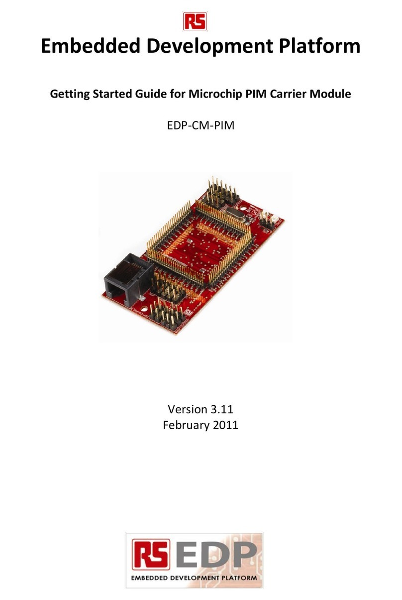
RS EDP-CM-1113 User manual

EmbeddedDevelopmentPlatform
GettingStartedGuideforLPCARM‐coreCommandModules
EDP‐CM‐1113,EDP‐CM‐1343,EDP‐CM‐1768,EDP‐CM‐2368
Version3.11
February2011

EDP-CM-LPCxxxx Getting Started V3.11
Electrocomponents plc Page 2
Contents
1. Introduction 3
2. Prepare to run the ‘Hello World’ Program 4
2.1 Software requirements.................................................................... 4
2.2 Hardware requirements................................................................... 4
3. Build and run ‘Hello World’ 5
3.1 Load the Project.............................................................................. 5
3.2 Build the Project.............................................................................. 5
3.3 Download and program target Flash memory................................. 6
4. Build your own Project 6
4.1 Creating a new Project.................................................................... 7
5. Conclusion 7
6. Appendix 1 EDP I2C Bus Device Addresses 8

EDP-CM-LPCxxxx Getting Started V3.11
Electrocomponents plc Page 3
1. Introduction
TogetthemostoutoftheEDPplatformit’simportanttounderstandtheconceptoftheEDPsystem
correctly.ThisisdetailedintheusermanualfortheBaseBoardswhichcanbedownloadedasapdf
fileRSEDP‐BB‐SystemBaseBoardUserManualVx,fromtheRSEDPwebsite.
Thebaseboardscomeinboth2positionand4positionformatsandshareacommonusermanual.
Pleasereadthismanualtogetanunderstandingofthesystem.
EachoftheCommandModules(CM)andApplicationModules(AM)hasitsownusermanual,so
againthesedocumentsmustbereadtogetanunderstandingonhowtousethemodules.
EachoftheboardscomeswithitsownsuiteofsoftwaretofullyexercisetheEDPApplication
ModulesandtheperipheralsavailableontheMCUdevice.
AnEDPsystemusuallyconsistsofoneCommandModuleandoneormoreApplicationsModules
pluggedintoaBaseBoard.AminimumsystemjusthasaCommandmoduleandBaseBoard,for
exampleasimplewebserveroperatingthroughanEthernetconnection.
TheCommandModuledictateswhetherthewholesystemusesasupplyvoltageof+3.3Vor+5.0V.
ThisparticularCMmoduleusea+3.3Vmicrocontroller(MCU)andsotheboardisconfiguredassuch.
TheusercanchecktheVcc_CMsignalontheBaseBoardbreak‐outheadertoconfirmthesystem
voltage.
Thereare100pinsontheMCUandtheseareconnectedviavariouslinkoptionstotheBaseBoard.
TheBaseBoardthenroutesthesesignalstotheApplicationModulestherebyallowingtheCM
ModuletocommunicatewiththeApplicationModules.
AsmanyoftheMCUpinshavemorethanonefunctionitcanmakethemappingoftheconnections
rathercomplexsothereareadditionalsupportdocumentsavailabletohelpyouwiththis.Thefirstis
thePinAllocationSpreadSheet.OnespreadsheetisavailableforeachoftheCMModules.Theone
fortheNXPfamilyofARM‐basedmodulesiscalled:
PinAllocation‐100pinNXPCommandModuleRevxx
ThisspreadsheetalsoformspartoftheUserManualfortheLPCxxxxCMmodule.Itdetailswhichpins
aremappedtotheBaseBoardbackplaneandthevariouslinkoptionswhichneedtobeconfiguredto
connectthemaccordingly.
TogetanappreciationofhowtheApplicationModulesaremappedtothebackplaneandhowthe
CPUModulecanconnecttothem,aMappingAidexists.TheonefortheLPC1768moduleiscalled:
MappingAidRS‐EDPNXPLPC1768Revxx
(NamemayvaryslightlyforotherNXPmodules)
ThismappingaidalsoformspartoftheUserManualfortheLPCModuleandataglanceyoucansee
whatresourcesarerequiredtogetthebestoutofeachApplicationModule.
Otherusefuldocumentsyouwillneedarethecircuitdiagramsforthemodulesyouwishtouse.
Thesearecontainedinthebackofeachusermanual.
SobeforeyoustarttousetheRSEDPsystemmakesureyouhavetohandthefollowingdocuments:
•BaseBoardUserManual
•AppropriateCMmoduleUserManual
•ApplicationModuleUserManuals(asrequired)

EDP-CM-LPCxxxx Getting Started V3.11
Electrocomponents plc Page 4
2. Prepare to run the ‘Hello World’ Program
ProgramdevelopmentisperformedonaPCrunningsuitablesoftware,andaplug‐inhardware
‘dongle’isrequiredasaprogramming/debuginterfacebetweenthePCandtheCMmodule.
2.1 Software requirements
Tobuild,downloadandrunyourfirstprogramyouwillneedtohaveasuitable
IntegratedDevelopmentEnvironment(IDE)runningonaPC.Ifnecessary
downloadKeilµVision4forARMprocessorsfromtheKeilwebsite.Thisisa
full‐featuredfreetrialversionthatislimitedto32Kbytesofoutputcode.You
canupgradetothefullversionlaterortryoneofthealternativesdiscussedin
anappendixtotheUserManual.TheIDEhandlesallaspectsofcode
productionasitcontainsasourcecodeeditor,assembler,Ccompiler,Flash
programmeranddebugtools.
2.2 Hardware requirements
TheKeilIDEneedsahardwareprogramming/debugdonglewhichallowsthe
CMmoduletobelinkedviaUSBtotheIDErunningonthePC.Ifyoualready
runKeilµVisionthenyoushouldalreadyhavetheinterfaceintheformofa
ULINK2module.Ifnot,thenasuitableunitcanbeobtainedfromRSunderthepartno.703‐9241.
ThesoftwareinsidethedongleisupgradedautomaticallybyKeilµVisionwhenitispluggedintothe
hostcomputer.ItsupportsclassicARM7/ARM9architecturesaswellasthelaterCortexdevices.
JTAGandSWDarebothsupported.
ThecorrectorientationofthedongleontheCMmodule

EDP-CM-LPCxxxx Getting Started V3.11
Electrocomponents plc Page 5
3. Build and run ‘Hello World’
3.1 Load the Project
•PlugthedongleintotheCMmodulenotingtheorientationinthepictureabove.
•ConnectthedongletoaUSBportonthehostcomputer.
•TurnonpowertotheBaseBoard.
•Downloadthe‘EDPLPCxxxxHelloWorld’folderfromtheEDPwebsitetoyourC:drive.
•RunKeilµVision4onthehostcomputer.
•ClickonOpenProjectfromtheProjectmenuandnavigatetothe‘EDPLPCxxxxHelloWorld’
folder.Doubleclickon‘Hello_World’toloadtheprojectfiles.
•Thescreenwillnowappearasbelow:
NotethatthefolderalreadycontainsallthenecessarysourcecodefilestogetherwiththeBuildfiles
producedbytheIDE.TodemonstratetheprocedurewewillnowperformtheBuildandLink
operations.
3.2 Build the Project
•Click the Rebuild button on the Build toolbar (see picture below). The various files are
compiled and linked, progress being reported in the Build Output pane.
•If there are any compilation errors they will be reported here and linking will not take place.
Double clicking on a particular error message will take you to the offending line of source code
in the edit pane above.

EDP-CM-LPCxxxx Getting Started V3.11
Electrocomponents plc Page 6
3.3 Download and program target Flash memory
•IfzeroerrorsarereportedthenthecodecanbedownloadedtothetargetMCUand
programmedintoitsFlashmemory.ClickontheDownloadbuttonontheBuildtoolbar.
•PresstheResetbuttonontheEDPBaseBoardandoneofthetwoyellowUserLEDsonthe
CMmoduleshouldbeginflashingindicatingasuccessfuldownloadandprogram.
Rebuild Project button
Download to Target button
4. Build your own Project
Theprocedureforbuildingandprogrammingyourownprojectisexactlyasoutlinedaboveusing
yourownprojectfoldercontainingsource(.c)andheader(.h)files.
TheHelloWorldprogramdoesnotuseanyEDPApplicationModulehardwarebutyourprojects
probablywill,sothenecessarydriverswillneedtobeincludedinyourfolder.Downloadthesefrom
theEDPwebsite.NotethatMCU‐specificdriverswillalsoberequired:seeexampleabove.

EDP-CM-LPCxxxx Getting Started V3.11
Electrocomponents plc Page 7
4.1 Creating a new Project
•ClickonNewµVisionProjectfromtheProjectmenuandnavigatetoyourprojectfolder
containingyoursourcefiles.
•TypeinaprojectnameandclickonSave.YouwillnowbeaskedtoselectatargetMCU
device.Inthiscaseselect‘NXP’andthenthepartnumberfromthedrop‐downlist.
•Right‐clickon‘SourceGroup1’intheProjectpane(expandedfrom‘Target1’)andthenon
‘AddFilestoGroup’.SelectandAddallyoursource(.c)files.Youcanrename‘Target1’and
‘SourceGroup1’andcreateothergroupsforotherfilesbyright‐clickingon‘Target1’and
thenclickingonManageComponents…
•Double‐clickonfile:system_LPCxxxx.candselecttheConfigurationWizardtab.Locatethe
‘PowerControlforPeripheralsRegister’andticktheboxesofperipheralsystemsusedby
yourproject.Resavethefilewhenfinished.Theremaybeothersettingsthatneedchanging,
butthedefaultsshouldgetthingsrunning.
•Buildandloadtheprojectasbefore.
5. Conclusion
ThisisonlyabasicintroductiontotheKeilIDE;morecompleteinformationandadescriptionofall
thedebuggingfeaturescanbefoundontheKeilwebsite.
RefertotheUserManualfortheseCMmodulesfordetailsofalternativeprogramdevelopmenttools
whichcanbeusedwithEDP.

EDP-CM-LPCxxxx Getting Started V3.11
Electrocomponents plc Page 8
6. Appendix 1 EDP I2C Bus Device Addresses
8‐bitaddressformatisused:theLSBisreservedastheread‐writebit.Theseaddressesaredefinedin
file:I2C‐Directory.h
BaseBoard
BB_DIP=0x40
8‐bitDIPSwitch
AddresssetbyjumperlinkJP501providingpossiblerangeofaddresses:0x40(default),0x42.
BB_EEPROM=0xA2
Serial4KBEEPROMmemory
AddresssetbyjumperlinksJ601toJ603providingpossiblerangeofaddresses:0xA0,0xA2
(default),0xA4,0xA6,0xA8,0xAA,0xAC,0xAE.
CommunicationsModuleEDP‐AM‐CO1
CO1_RTC=0xA0
Real‐TimeClockandSRAM
AddresssetbyjumperlinkJ304providingpossiblerangeofaddresses:0xA0(default),0xA2.
DigitalI/OModuleEDP‐AM‐DIO54
DIO54_Out=0x46
Digitaloutputlatch
AddresssetbyjumperlinksB305toB307providingpossiblerangeofaddresses:0x40,0x42,
0x44,0x46(default),0x48,0x4A,0x4C,0x4E.
DIO54_In=0x44
Digitalinputlatch
AddresssetbyjumperlinksB302toB304providingpossiblerangeofaddresses:0x40,0x42,
0x44(default),0x46,0x48,0x4A,0x4C,0x4E.
AnalogueInputModuleEDP‐AM‐AN16
AN16_ADC=0x6A
12‐channel10‐bitAnaloguetoDigitalConverter
AN16_Pot=0x58
DigitalPotentiometerforsettingfiltercut‐offfrequencyofchannelsAN0andAN1
AddresssetbyjumperlinksJ305&J306providingpossiblerangeofaddresses:0x58
(default),0x5A,0x5C,0x5E.
NotethatjumperlinksJ204&J205selectbetweenCTRL_I2C(default)andI2C_GEN0buschannels.
DualBLDCMotorModuleEDP‐AM‐MC2
MICROCHIP_MOTOR_DRIVER_BASE=0x80
dsPICU201
AddresssetbyjumperlinksJ201toJ203providingpossiblerangeofaddresses:0x80
(default),0x82,0x84,0x86,0x88,0x8A,0x8C,0x8E.
dsPICU202
AddresssetbyjumperlinksJ205toJ207providingpossiblerangeofaddresses:0x80,0x82
(default),0x84,0x86,0x88,0x8A,0x8C,0x8E.
NotethatspareaddressesallowuptofourMC2modulesperbaseboard
Miscellaneous
SRF08=0xE0
DaventechSRF08UltrasonicRangefindermodule
This manual suits for next models
3
Table of contents
Other RS Control Unit manuals
Popular Control Unit manuals by other brands

BFT
BFT ALPHA BOM Installation and user manual

Viessmann
Viessmann VITOTRONIC 100 Installation and service instructions

Crane
Crane D1088 Installation, operating and maintanance instructions

Pittway
Pittway SYSTEM SENSOR M500M Installation and maintenance instructions

rada
rada 566 Installation and Maintenance

indie
indie iND83405 Quick start user guide

CAME
CAME ZLJ24 installation manual

Unitronics
Unitronics Land Vision280 user guide

Ensemble Designs
Ensemble Designs Avenue 5030 user guide

Watts
Watts IntelliFlow A2C-M1 operating instructions

Ericsson
Ericsson ROK 101 007 manual

Victaulic
Victaulic FireLock NXT 764 Series Installation, Maintenance, and Testing Manual