manuals.online logo
Brands
  1. Home
  2. •
  3. Brands
  4. •
  5. M-system
  6. •
  7. Control Unit
  8. •
  9. M-system R7L-EC16B User manual

M-system R7L-EC16B User manual

5-2-55, Minamitsumori, Nishinari-ku, Osaka 557-0063 JAPAN
Phone: +81(6)6659-8201 Fax: +81(6)6659-8510 E-mail: info@m-system.co.jp
EM-7804-K Rev.1 P. 1 / 3
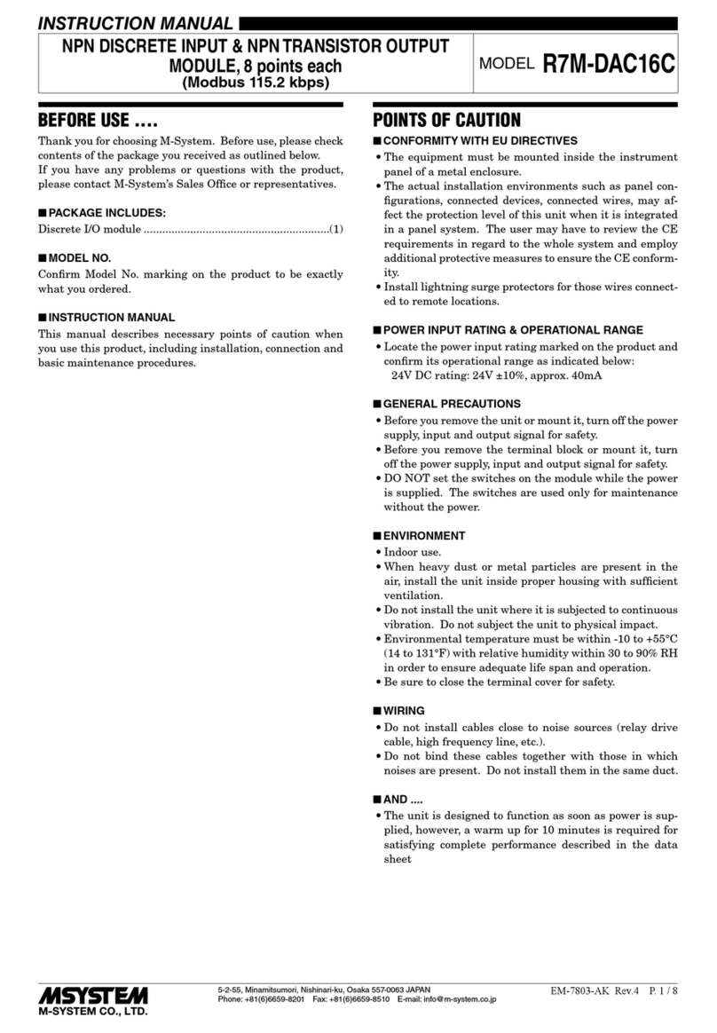
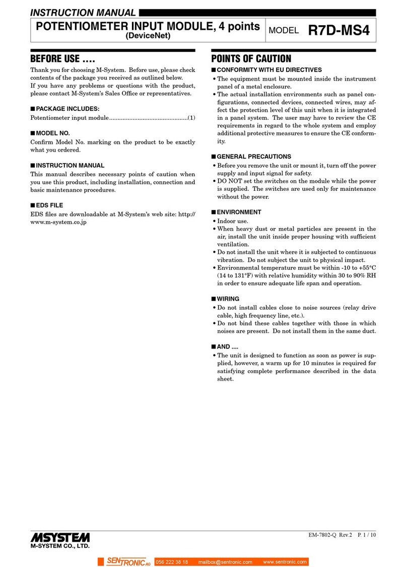
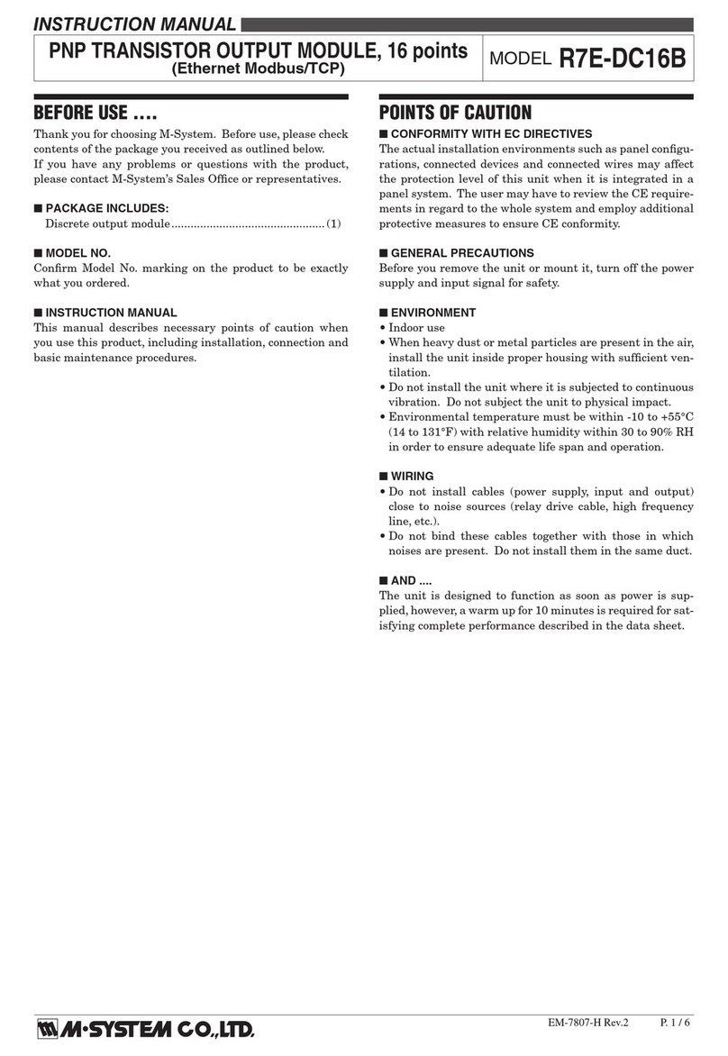
INSTRUCTION MANUAL
PNP TRANSISTOR OUTPUT EXTENSION MODULE, 16 points
(LONWORKS)MODEL
R7L-EC16B
BEFORE USE ....
Thank you for choosing M-System. Before use, please check
contents of the package you received as outlined below.
If you have any problems or questions with the product,
please contact M-System’s Sales Office or representatives.
■PACKAGE INCLUDES:
Transistor output extension module..................................(1)
■MODEL NO.
Confirm Model No. marking on the product to be exactly
what you ordered.
■INSTRUCTION MANUAL
This manual describes necessary points of caution when
you use this product, including installation, connection and
basic maintenance procedures.
POINTS OF CAUTION
■POWER INPUT RATING & OPERATIONAL RANGE
• Locate the power input rating marked on the product and
confirm its operational range as indicated below:
24V AC rating: 24V ±10%, 50/60 Hz, approx. 30mA
24V DC rating: 24V ±10%, approx. 20mA
■GENERAL PRECAUTIONS
• Before you remove the unit or mount it, turn off the power
supply and output signal for safety.
■ENVIRONMENT
• Indoor use.
• When heavy dust or metal particles are present in the
air, install the unit inside proper housing with sufficient
ventilation.
• Do not install the unit where it is subjected to continuous
vibration. Do not subject the unit to physical impact.
• Environmental temperature must be within -10 to +55°C
(14 to 131°F) with relative humidity within 30 to 90% RH
in order to ensure adequate life span and operation.
■WIRING
• Do not install cables close to noise sources (relay drive
cable, high frequency line, etc.).
• Do not bind these cables together with those in which
noises are present. Do not install them in the same duct.
■FUNCTIONAL BLOCK SETTING
• Functional blocks regarding the extension module are set
by the basic module. Refer to the instruction manual for
the basic module for detailed information.
■AND ....
• The unit is designed to function as soon as power is sup-
plied, however, a warm up for 10 minutes is required for
satisfying complete performance described in the data
sheet.
COMPONENT IDENTIFICATION
0123456789ABCDEF
10 11 12 13
2341
15 16 17 18
7896
14
5
Discrete Output Status Indicator LED
Output Terminals
■DISCRETE OUTPUT STATUS INDICATOR LED
Used to show discrete output signal status.
ON : LED ON
OFF : LED OFF
■OUTPUT TERMINAL ASSIGNMENT
10
+24V
11
Y1
12
Y3
1
0V
2
Y0
3
Y2
13
Y5
4
Y4
14
Y7
5
Y6
15
Y9
6
Y8
16
YB
7
YA
17
YD
8
YC
9
YE
18
YF
NO.
ID FUNCTION
NO.
ID FUNCTION
1 0V 0V 10 +24V
24V DC (common)
2 Y0 Output 0 11 Y1 Output 1
3 Y2 Output 2 12 Y3 Output 3
4 Y4 Output 4 13 Y5 Output 5
5 Y6 Output 6 14 Y7 Output 7
6 Y8 Output 8 15 Y9 Output 9
7YA Output 10 16 YB Output 11
8 YC Output 12 17 YD Output 13
9 YE Output 14 18 YF Output 15
R7L-EC16B
5-2-55, Minamitsumori, Nishinari-ku, Osaka 557-0063 JAPAN
Phone: +81(6)6659-8201 Fax: +81(6)6659-8510 E-mail: info@m-system.co.jp
EM-7804-K Rev.1 P. 2 / 3
CONNECTING THE EXTENSION MODULE
1) Remove the extension connector cover located at the side
of the basic module.
2) Connect the extension module.
3) Mount the combined module on a DIN rail.
TERMINAL CONNECTIONS
Connect the unit as in the diagram below.
■EXTERNAL DIMENSIONS unit: mm (inch)
11.5
(.45)
10 11 12 13
2341
15 16 17 18
789
6
14
5
94 (3.70)
30 (1.18) [5 (.20)]
DIN RAIL
35mm wide
54 (2.13)
17 (.66)
18–M3 SCREW
TERMINALS
for OUTPUT
6 (.24)
3 (.12)5.5 (.22) 50 (1.97) 18.5 (.73)
R7L-EC16B
5-2-55, Minamitsumori, Nishinari-ku, Osaka 557-0063 JAPAN
Phone: +81(6)6659-8201 Fax: +81(6)6659-8510 E-mail: info@m-system.co.jp
EM-7804-K Rev.1 P. 3 / 3
■CONNECTION DIAGRAM
EXTENSION CONNECTOR
10
17
18
1
YD
16
YB
0V
YF
15
Y9
14
Y7
13
Y5
12
Y3
11
Y1
9YE
8YC
7YA
6Y8
5Y6
4Y4
3Y2
+24V
Y0
2
■
Output Connection Example
10
1
2
Y0
0V
+24V –
+
18
YF
WIRING INSTRUCTIONS
■SCREW TERMINAL
Torque: 0.5 N·m
■SOLDERLESS TERMINAL
Refer to the drawing below for recommended ring tongue
terminal size. Spade tongue type is also applicable.
Applicable wire size: 0.25 to 1.65 mm2(AWG 22 to 16)
Recommended manufacturer: Japan Solderless Terminal
MFG. Co., Ltd, Nichifu Co., Ltd
6 (.24) max
3.3 (.13) max
mm (inch)

Other M-system Control Unit manuals

M-system R30MS4 User manual

M-system

M-system R30MS4 User manual

M-system R7M-EC8C User manual

M-system

M-system R7M-EC8C User manual

M-system R30US2 User manual

M-system

M-system R30US2 User manual

M-system R8-FS16N User manual

M-system

M-system R8-FS16N User manual

M-system Mini-M M2DL User manual

M-system

M-system Mini-M M2DL User manual

M-system R5T-DA4 User manual

M-system

M-system R5T-DA4 User manual

M-system R3-ND1 User manual

M-system

M-system R3-ND1 User manual

M-system R7E-DC16B User manual

M-system

M-system R7E-DC16B User manual
M-system R7HL-DAC16C User manual

M-system

M-system R7HL-DAC16C User manual

M-system R5-TS User manual

M-system

M-system R5-TS User manual

M-system R7M-CT4E User manual

M-system

M-system R7M-CT4E User manual

M-system M6NPS2 User manual

M-system

M-system M6NPS2 User manual

M-system R7C-EC16A User manual

M-system

M-system R7C-EC16A User manual

M-system R8-SVT8 User manual

M-system

M-system R8-SVT8 User manual

M-system R3-PA4A User manual

M-system

M-system R3-PA4A User manual

M-system R3-SV8C User manual

M-system

M-system R3-SV8C User manual

M-system R8-DCM16ALH User manual

M-system

M-system R8-DCM16ALH User manual

M-system R3-PD16 User manual

M-system

M-system R3-PD16 User manual

M-system M8YC User manual

M-system

M-system M8YC User manual

M-system R7C-EA8 User manual

M-system

M-system R7C-EA8 User manual

M-system R3-PA8 User manual

M-system

M-system R3-PA8 User manual

M-system R3-PA2 User manual

M-system

M-system R3-PA2 User manual

M-system R7HL-DC8C User manual

M-system

M-system R7HL-DC8C User manual

M-system R3-NC2 User manual

M-system

M-system R3-NC2 User manual
Popular Control Unit manuals by other brands

Trenz Electronic TE0720 Schematics

Trenz Electronic

Trenz Electronic TE0720 Schematics

BENDIX RV-4 PRESSURE REDUCING VALVE General description

BENDIX

BENDIX RV-4 PRESSURE REDUCING VALVE General description

Vex Robotics VEX IQ Smart Radio user guide

Vex Robotics

Vex Robotics VEX IQ Smart Radio user guide

TERMA KTX 1 user manual

TERMA

TERMA KTX 1 user manual

Nice UDL 2 Instructions and information for installation and use

Nice

Nice UDL 2 Instructions and information for installation and use

Avaya J100 Series manual

Avaya

Avaya J100 Series manual

Pepperl+Fuchs KFD2-DWB-Ex1.D instruction manual

Pepperl+Fuchs

Pepperl+Fuchs KFD2-DWB-Ex1.D instruction manual

Vortice Sicurbox Instruction booklet

Vortice

Vortice Sicurbox Instruction booklet

Comelit FT/GEN/05 Technical manual

Comelit

Comelit FT/GEN/05 Technical manual

Automationdirect.com Productivity 2000 P2-08TAS manual

Automationdirect.com

Automationdirect.com Productivity 2000 P2-08TAS manual

Nexus NEX3031 instructions

Nexus

Nexus NEX3031 instructions

VAT 650 Series Installation, operating,  & maintenance instructions

VAT

VAT 650 Series Installation, operating, & maintenance instructions

Flotrol F60 Service manual

Flotrol

Flotrol F60 Service manual

Omron SYSMAC C500-NC113 Operation manual

Omron

Omron SYSMAC C500-NC113 Operation manual

Shinko QMC1-MT instruction manual

Shinko

Shinko QMC1-MT instruction manual

System Sensor IM-10 Installation and maintenance instructions

System Sensor

System Sensor IM-10 Installation and maintenance instructions

Oppermann Regelgeräte STG 1.2 manual

Oppermann Regelgeräte

Oppermann Regelgeräte STG 1.2 manual

Elster ACM WAVE SYSTEM RF operating instructions

Elster

Elster ACM WAVE SYSTEM RF operating instructions

manuals.online logo
manuals.online logoBrands
  • About & Mission
  • Contact us
  • Privacy Policy
  • Terms and Conditions

Copyright 2025 Manuals.Online. All Rights Reserved.