Polon-Alfa CDG 6000 Installation guide

GAS DETECTION CONTROL PANEL
CDG 6000
Operation and Maintenance Documentation
ID-E364-001
Edition 1

2 ID-E364-001
This Operation and Maintenance Documentation describes CDG 6000 gas detection control panel
which fulfills main
requirements of the following Regulation of the European Parliament and of the Council (EU) and
European Union
Directives:
LVD Directive 2014/35/EC related to electrical equipment for use
within stipulated voltage limits;
EMC Directive (EU) 2014/30/EC concerning electromagnetic compatibility.
CDG 6000 gas detection control panel received Declaration of Conformity number 1/E364/2017/PL.
You can download the Declaration of Conformity from the website www.polon-alfa.pl
Read this manual before installation and operation. Failure to observe the instructions in this manual
may be dangerous or result in a breach of regulations in force.
The manufacturer Polon-Alfa Spółka z ograniczoną odpowiedzialnością Sp. k. (formerly „POLON-
ALFA” Zakład Urządzeń Dozymetrycznych sp. z o.o.) accepts no liability for any damage resulting from
usage inconsistent with the manual.
Worn out product, not suitable for further use must be handed over
to an electrical and electronic equipment waste collection point.

ID-E364-001 3
Note - The manufacturer reserves the right to introduce changes
Table of Contents
TOC

4 ID-E364-001
1. Introduction
1.1. Documentation structure
The Operation and Maintenance Documentation (OMD) describes CDG 6000 gas detection control
panel (fig. 1.1).
Fig. 1.1 CDG 6000 control panel

ID-E364-001 5
This OMD is intended for designers, installers and maintenance personnel of the CDG 6000. It
includes information required for control panels installation, programming, servicing and operation.
1.2. Control panel purpose
CDG 6000 gas detection control panel (hereinafter referred to as the control panel) is a stationary
microprocessor device for leakage detection of flammable gases and carbon oxide. The control panel
can cooperate with up to 16 detectors simultaneously, has 4 control outputs for external devices, 4
control inputs and control output for gas cut off valve.
The control panel is adapted for operation in rooms with low dustiness, within temperature range
from - 10°C to +55°C and relative air humidity up to 80% at +55°C.
1.3. Safety conditions
1.3.1. Electric shock protection
CDG 6000 gas detection control panels are class II protection devices.
The insulation of the circuits supplying electrical power 230V/50Hz is reinforced and can withstand
test voltage of 2800V whereas low voltage circuits insulation (below 42V) can withstand test voltage
of 700VDC.
1.3.2. Installation and equipment safety
The distance between the low-voltage installation and the power and lightning protection systems
should be compliant with requirements to prevent unwelcome interactions.
Protective grounding is recommended to assure system resistance to electromagnetic interference.
Standby batteries should be placed in the control panel at the end of installation.
Components of this unit are sensitive to heat. The maximum ambient temperature must not exceed
+55°C. The air humidity in the rooms where the unit operates must not exceed 80 %. Do not place
any objects on the device and protect the device from water getting into it.
1.3.3. Repairs and maintenance
The maintenance works and periodical inspections should be conducted by authorised employees of
companies which have been authorised or trained by Polon-Alfa personnel. All repair works must be
done exclusively by the manufacturer.
Polon-Alfa accepts no responsibility for the operation of devices maintained and repaired by
unauthorised personnel.
1.3.4. Fuse replacement
When replacing fuses use only spare ones of the appropriate type and nominal value. Correct types
and nominal values are described in chapter 8.1 of this instruction.

6 ID-E364-001
2. Control panel structure and assemblage
CDG 6000 control panel requires 12V 2.3Ah lead-acid battery for correct operation. The battery is
placed inside the enclosure. Battery maximum external dimensions are as follows: 178 x 34 x 64mm.
The control panel can cooperate with PSG-6000 series gas detectors. The control panel detection line
may include up to 16 detectors of different types.
Table 1: PSG-6000 series detectors selection.
Detected Gas
CNG
(natural gas)
LPG
(propane – butane)
CO
(carbon oxide)
Model
PSG-6001
PSG-6002
PSG-6003
PSG-6103
Sensor Model
MSG-6001
MSG-6002
MSG-6003
MSG-6003
Sensor Type
semiconductor
semiconductor
electrochemical
electrochemical
Sensor power
supply
External 9-30V
External 9-30V
External 9-30V
From detection line
The detectors connected with the control panel may be powered with external power supply or 12V
power supply line provided in the control panel for the user.
The control panel may additionally be fitted with MKA-60 module. This module expands the control
panel capabilities with ACOM 6.0 functionality. This functionality allows for direct cooperation of the
control panel with POLON 6000 fire alarm systems.
2.1. Components layout in the control panel
Fig. 2.1.1 CDG 6000 control Panel – top view

ID-E364-001 7
Fig. 2.1.2 CDG 6000 control panel
Component placement inside the control panel is depicted in figure 2.1.1 and 2.1.2:
1. RESET button
2. USB port
3. Microprocessor programming mode switch
4. PK1 relay connector
5. PK2 relay connector
6. PK3 relay connector
7. PK4 relay connector
8. Detector lines connector
9. Connector for control panel connection with POLON-ALFA fire alarm control panel detection
line
10.LK1 and LK2 control lines connector
11.LK3 and LK4 control lines connector
12.Gas cut-off valve connector
13.External devices 12V power supply connector
14.”Battery Start” button
15.Control panel 230VAC power supply connector with F1 – 630mA fuse enclosure
16.External devices power supply output fuse 12V – 630mA
17.Detection line grounding control
18.S1 jumper that sets the detection line maximum load current

8 ID-E364-001
3. Technical data
Table 3.1 Control Panel Technical Specification
POWER SUPPLY
Main supply voltage
230VAC + 10% - 15%
The frequency of the main supply voltage
47 ... 63Hz
Maximum supply current
150mA
Backup power supply source
12V 2.3Ah Battery
Current drawn from the batteries during the stand-by (control panel)
< 100mA
POLON 6000 system addressable detection line current consumption
< 0.6mA
INPUTS
LK1-LK4 control lines
Typical 0.3mA
3 + 2 (short circuit and opening)
Control current value (supervision mode)
Number of differentiated input states
Detection line
16
50mA / 2 x 45Ω
20mA / 2 x 100Ω
22mA / 2 x 75Ω
40Ω
300nF
100kΩ
Maximum number of detectors in a detection line
Maximum load current for detection line / Maximum resistance of
the line wires depending on jumper settings:
- jumper S1 (S2) in position 1-2
- jumper S1 (S2) in position 2-3
The maximum line wires resistance between consecutive elements:
The maximum allowable line wires capacity:
Minimum insulation resistance of installation wiring:
OUTPUTS
External power supply line:
12VDC +5% -5%
500mA
External power supply line voltage
Continuous current from external power supply line
PK1-PK4 relay outputs
8A/ 250VAC
8A/ 30VDC
NO/NC contact current-voltage carrying capacity:
Cut-off valve control output:
12V
11A
from 0.2 to 1 second
from 10 to 60 seconds
Output voltage:
Maximum output current:
Control pulse time (programmable)
Minimum time between control pulses (programmable)

ID-E364-001 9
ENVIRONMENT
Transportation temperature
-25°C ... +55°C
Operating temperature
-10°C ... +55°C
Permissible relative humidity during operation
80% at +55°C
CONSTRUCTION
Enclosure tightness
IP 54
Dimension (without fixation and legs) L x H x D
300 x 230 x 86 mm
Weight (without batteries)
< 2.3kg

10 ID-E364-001
4. Functionality description
4.1. General description
CDG 6000 gas detection control panel is intended for signalization of gas leakages and gas
concentration exceedance and allows for:
-exceedance detection for 3 gas concentration thresholds;
-automatic or manual cut-off valve closure;
-automatic control over 4 devices;
-devices state control;
-automatic control for own modules and control panel circuits;
-transfer of main information (alarm, fault, executive devices state) to parent systems, e.g.
POLON 6000 system.
4.2. Main control panel states
4.2.1. Detection
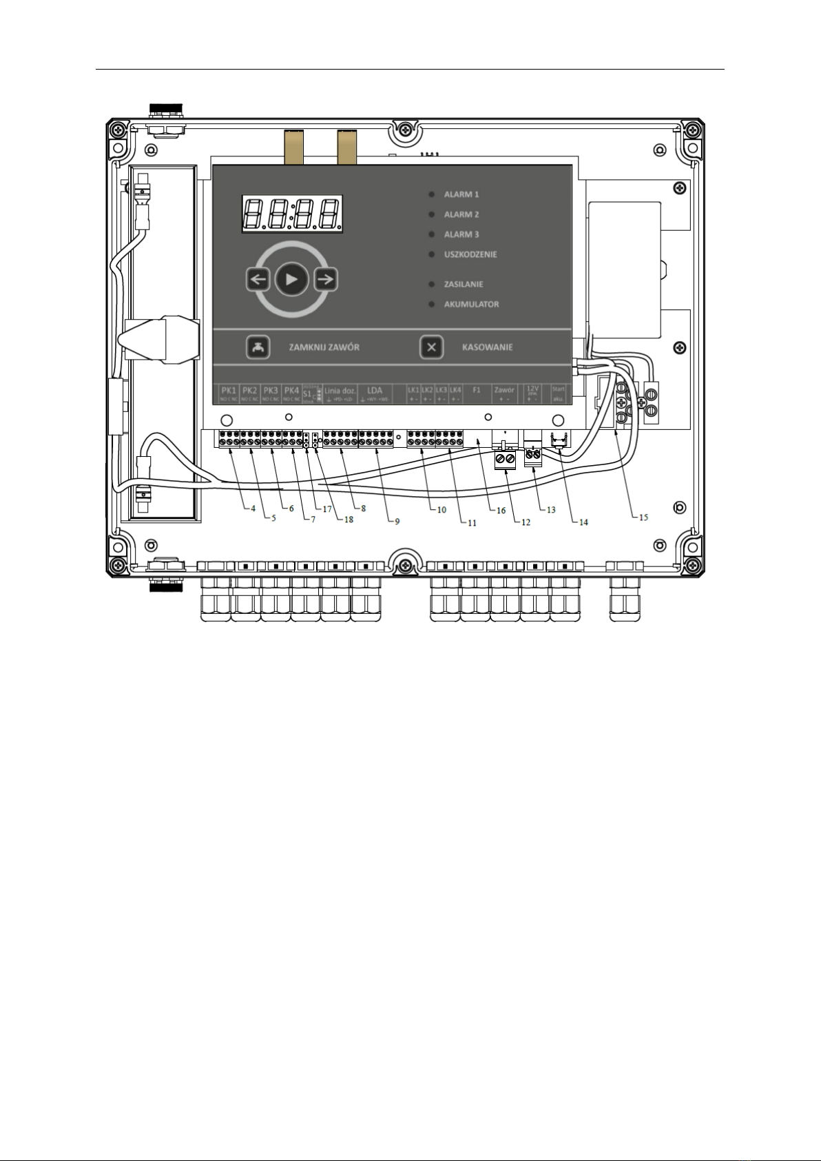
In the detections state, the power supply indicator should shine continuously on the control panel.
Alarm and fault indicators off. Current time shown on the display. Press arrow button to show
current date on the display.
4.2.2. Alarm signalization
The control panel may signal three alarm stages. Current alarm stage is presented with ALARM 1 – 3
indicators. It is a sum of alarms from all detectors connected with the control panel. Alarm
occurrence in any detector is conveyed with warning indicator light and continuous audible signal.
Blinking indicator and intermittent sound signal informs about stored alarms.
Furthermore, the display presents detailed information on alarm stage for each detector. You can
browse list of detectors signaling alarm with arrow buttons.
The figure depicts alarms presentation layout on the display. The first two digits are detector
number. The A letter in the third position of the display informs that alarm information is displayed.
Alarm stage is presented in the fourth display position with horizontal number segments. The current
alarm is indicated with continuously lit line. The upper line refers to the first stage alarm, the middle
line refers to the second stage alarm, and the bottom line refers to the third stage alarm. Alarms and
faults are stored in the device until they are cleared by the user. The stored information can be
cleared with CLEAR button on the user panel.
If the detectors are still in the alarm state during clearing, he alarm in the control panel will be
repeated. In order to mute the sound signal press and hold the CLEAR button until a dot is displayed
in bottom right corner. New fault occurrence will automatically trigger the sound signal.
Furthermore, the alarm and fault information is stored in non-volatile internal memory in the form of
event log. The log stores all events with their occurrence date and time. The event log content is
accessible using ”Konfigurator CDG 6000” configuration application.

ID-E364-001 11
4.2.3. Faults signalization
CDG 6000 control panel is equipped with extensive device and connected external devices self-
diagnostics system. Summary fault information is presented by FAULT indicator on the device panel.
Furthermore, similarly to alarms, the full list of faults is accessible using the device display.
When the control panel signals current or stored alarm the information on alarms are always
presented in the device display by default. In such a case use navigation button to toggle the screen
to the faults list.
The figure depicts an example of fault presentation in the display. The first two positions indicate the
damaged element. The third position of the fault information is always filled
with letter U. The fourth position denotes the fault code. The full list of faults is listed in the table.
Table 4.2.3.1 Fault codes
DETECTOR FAULTS
Detector
number
Fault code
Description
01-16
U
1
Detector base damage
2
Detector base EEPROM memory fault
3
Sensor does not respond or lack of sensor
4
Last 30 days of sensor calibration validity left.
5
Sensor calibration date passed.
6
Defective sensor.
7
The detector does not respond or lack of detector in the line.
8
Sensor EEPROM memory fault.
9
Incorrect sensor type.
A
Burn-in during operation.
b
shortcut insulator on,
CONTROL LINE FAULTS
Line
number
Fault code
Description
L1 - L4
U
1
Control line shorted
2
Control line open
EXTERNAL DEVICES FAULTS
Output
number
Fault code
P1 - P4
U
1
The device does not reach the expected state after switching it on.
2
The device does not reach the expected state after switching it off.

12 ID-E364-001
BATTERY FAULTS
A
U
1
Internal battery resistance exceeded.
2
Charging time exceeded.
3
Battery voltage too low.
4
No battery.
CONTROL PANEL FAULTS
S
U
1
No mains power supply.
2
No power supply of 27V detection line.
3
Damaged 12V output fuse.
4
Control panel internal memory fault.
5
MKA module does not respond.
DETECTOR LINE FAULTS
L
U
1
Undeclared components in the line.
2
Changed components in the line.
3
Line grounding.
4
Loop line open.
5
Line output short circuit.
6
Loop input short circuit.
7
Incorrect loop RC parameters.
4.2.4. Power supply state signaling
The control panel is fitted with two indicators which present the power supply state. The POWER
SUPPLY indicator presents the mains power supply state. Continuous light indicates correct mains
power supply, whereas intermittent light indicates no mains power supply.
The BATTERY indicator presents the internal battery state. Continuous light indicates battery
operation of the control panel, whereas intermittent light indicates battery fault. Short flashes of this
indicator inform about battery charging.
4.2.5. Detector localization
The control panel is equipped with a feature that localizes element in the line and activates signaling
LED in the detector. To activate this feature double click the required element with the left mouse
button in Detectors tab in the configuration dialog box. Activation of this feature is signaled with
circle in brackets icon as depicted in figure 4.2.5.2. To switch this feature off double click the element
again with left mouse button.
Put a magnet close to a detector near its label with magnet icon to display the number of this
element in the line with letter L as depicted in figure 4.2.5.1.
Fig. 4.2.5.1 The control panel screen when a magnet is close to detector number 14.

ID-E364-001 13
Fig. 4.2.5.2 Dialog box with localization icon next to detector number 5.
4.3. Control panel software version readout
In order to verify the control panel software version go to CONTROL PANEL STATE in the
configuration utility. The dialog box display the same information as the control panel and the
number of the device software version in its bottom left corner.
Fig. 4.3.1 Tab with control panel state.

14 ID-E364-001
5. External circuits connection
5.1. Detector line
Name
Purpose
PD+
PD-
Detectors line end input
LD+
LD-
Detectors line input
E
Display input
The detectors for detected gases are connected with the CDG control panel using specially designed
detection line. Each detector is assigned with unique address. The control panel may therefore
display state of each detector.
The detectors line may operate in two modes, as a radial or loop line. In the loop line mode, the line
end is connected with the control panel. The system is thus able to operate correctly even with line
breakage in one place.
The line is also immune to short circuits. The detectors are equipped with insulators which separate
the short circuit in such a way to assure operability of the maximum number of detectors.
When connecting detector line wires to the control panel, pay utmost attention to the line polarity as
well as correct cable screen connection with appropriate terminal.
5.2. Control relays outputs
Name
Purpose
NO
Normally open terminal (disabled)
C
Common terminal
NC
Normally connected terminal
(enabled)
The control panel is equipped with four universal relay outputs for control devices. The relay outputs
are potential-free and can handle direct and alternating current
5.3. Control inputs
Control inputs can receive alarms from external devices and control operation of devices controlled
directly by the control panel. Control inputs are parametric inputs. Apart from short circuit and
opening detection, the inputs distinguish 3 resistance ranges. This allows for full input control which
results in a connection with external device that is fully resilient to damage.

ID-E364-001 15
Resistance levels
Description
R < 240Ω
Shortcut
R = 750Ω (240 < R < 1.2kΩ)
State 1
R = 2kΩ (1.2kΩ < R < 3kΩ)
State 2
R = 6.3kΩ (3kΩ < R < 12kΩ)
State 3
R = 27kΩ (12kΩ < R)
Open
Each resistance range may be assigned with any system reaction. Control inputs may cooperate with
plain contact. Only shortcut and opening states are handled that mode.
Resistors are needed for full utilization of the control panel inputs. Figure 5.3.1 shows a method for
connection of a single connector in external device. This connection assures control over wires in the
case of short circuit or wires disconnection.
Figure 5.3.2 depicts connection of two external device contacts to one input. This type of connection
allows for detection of 3 states of the controlled device.
Fig. 5.3.1 Single contact connection to control
input using resistors.
Fig. 5.3.2 Two contacts connection to control
input using resistors.
5.4. Cut-off valve control output
The control panel is equipped with output for activation of cut-off valves. The output generates 12V
pulse. The output is fitted with built-in protection that limits the maximum current to 11A. Pulse time
may be programmed within the range from 0.2 to 1s.
The output is equipped with software protection against valve electromagnet damage. The
protection limits the possibility of valve activation before the end of the defined pause time.
NOTE. The valve may be properly energized only with a functional battery connected to the control
panel. Damaged or discharged battery does not allow for proper control pulse generation.
5.5. Power supply output

16 ID-E364-001
The control panel is fitted with 12V power supply output for detectors and external devices. The
maximum current of this output is limited to 500mA. The output is protected with a miniature fuse
NANO2630mA. The fuse state is controlled by the control panel; its failure is signaled as a fault.

ID-E364-001 17
6. Detection line input
The CDG 6000 control panel may directly cooperate with the POLON6000 system. The gas detection
control panel may be connected to the POLON6000 fire alarm system detection line with additional
module MKA-60. LDA connector is provided for this connection. The LDA connector is described in
the following table.
Name
Purpose
WE+
WE-
Detectors line input
WY+
WY-
Detectors line output
E
Display input
6.1. Battery connectors
The CDG 6000 control panel requires lead-acid battery for its correct operation. No connected
battery or a faulty battery results in fault signalization.
The battery in the control panel provides closing pulse for the cut-off valve. Inoperable battery
prevents valve activation.
Use only original wire set equipped with fuse socket to connect the battery to the control panel.
Battery specification:
Parameter
Value
Nominal voltage
12V
Capacity
2.3Ah
Maximum dimensions
length 180 x height 40 x
width 60
The battery must be definitely disconnected for storage of the control panel.

18 ID-E364-001
7. Control panel configuration and programming
The CDG 6000 control panel is configured and programmed using Konfigurator CDG6000 computer
application.
Konfigurator CDG6000 features:
-control panel parameters configuration, including:
-saving the configuration in a file
-reading the configuration from a file
-sending the configuration to the control panel
-reading the configuration from the control panel
-reading the event log, including:
-saving the log in a file
-reading the log from a file
-reading the log from the control panel
-printing the event list
-saving to a PDF file
-deleting the event list
-previewing the state and remote managing the control panel
-setting and reading the control panel system date and time
-using program context help.
The CDG control panel may be connected using USB port to a PC computer. Use USB cable with A
plug at one end and B plug at the other end to connect the computer with the control panel. For
longer distances between the computer and the control panel use so called active extension USB
cable. Upon connection, the USB port of the CDG 6000 control panel should be displayed by the
computer as USB Serial Port (COMxxx).
The application automatically detects the control panel connected with the computer and informs
about it with highlighted icon that is used to establish connection.

ID-E364-001 19
7.1. Control panel configuration
Create an empty configuration to start configuration of the control panel.
For this purpose use icon. Click this icon to display the following tab:
Fig. 7.1.1 Configuration dialog box.
When the configuration tab is visible icons for configuration read-out and write to disk are active.
Furthermore, if communication with the control panel is established icons for configuration read-out
and transfer to the control panel are also active.
The left side of the tab consists of menu with system elements available for configuration. Elements
grouped in the following categories:
- Detectors
- Inputs
- Outputs
- Control
- Control panel settings

20 ID-E364-001
7.1.1. Detectors configuration
In order to configure detects the line should be automatically configured. This procedure detects all
detectors connected with the control panel. To start the automatic configuration press
”Automatic configuration” button. This procedure runs until the ”Automatic configuration” button is
pressed again.
Upon the procedure completion the list should include all detectors connected with the control
panel. Click each item to display detailed detector information in the right side of the dialog box.
Furthermore, set the required sensor type for each detector. During operation, the control panel
continuously tests whether functional sensor of the required type is placed in each base.
Fig. 7.1.1.1 Configuration dialog box with an example of detector list.
Table of contents