Polon-Alfa POLON 4000 Series Manual

POLON 4000
INTERACTIVE FIRE DETECTION AND ALARM SYSTEM
UCS-6000
UNIVERSAL FIRE CONTROL PANEL
Installation and Maintenance Manual
IK-E345-001E
I Edition

2 IK-E283-001E
The UCS-6000 Universal Fire Control Panel covered by the present manual complies with the
requirements of the Technical Approval No. CNBOP AT-0401-0331/2012 and the following European
Union Directives:
LVD 2006/95/WE on electric equipment applicable in certain voltage ranges;
EMC 2004/108/WE on electromagnetic compatibility.
The universal control panel has been approved with the Certificate of Conformity No. 2798/2012
issued by the Scientific and Research Centre for Fire Protection (CNBOP) Józefów, Poland, an EU
notified authority No. 1438, confirming its compliance with the requirements of Technical Approval
that meets requirements of the PN-EN 12101-10 , PN-EN 54-4 standards.
The certificate may be downloaded from www.polon-alfa.pl web site.
Read the manual carefully before the detector assembling and commissioning.
Any nonconformity with the instructions contained in the manual may be harmful or may cause
violation of the law in force
POLON-ALFA bears no responsibility for any damage resulting from usage inconsistent with the
manual.
A waste product, unsuitable for further use, shall be passed to
a waste electric and electronic equipment collection point.
NOTE: The manufacturer reserves the right to change specifications of products at any time
without prior notice.

IK-E283-001E 3
Contents
1. Introduction...........................................................................Error! Bookmark not defined.
1.1. Documentation contents ...................................................Error! Bookmark not defined.
1.2. Control panel application...................................................Error! Bookmark not defined.
1.3. Safety conditions................................................................Error! Bookmark not defined.
1.3.1. Electric shock protection............................................Error! Bookmark not defined.
1.3.2. Installation and eqipment safety................................Error! Bookmark not defined.
1.3.3. Repair works and maintenance..................................Error! Bookmark not defined.
1.3.4. Fuse replacement.......................................................Error! Bookmark not defined.
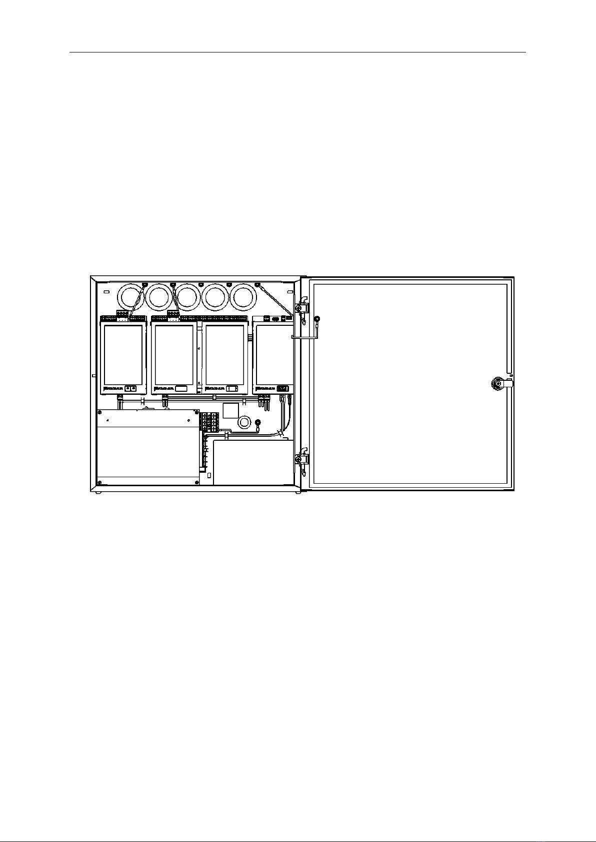
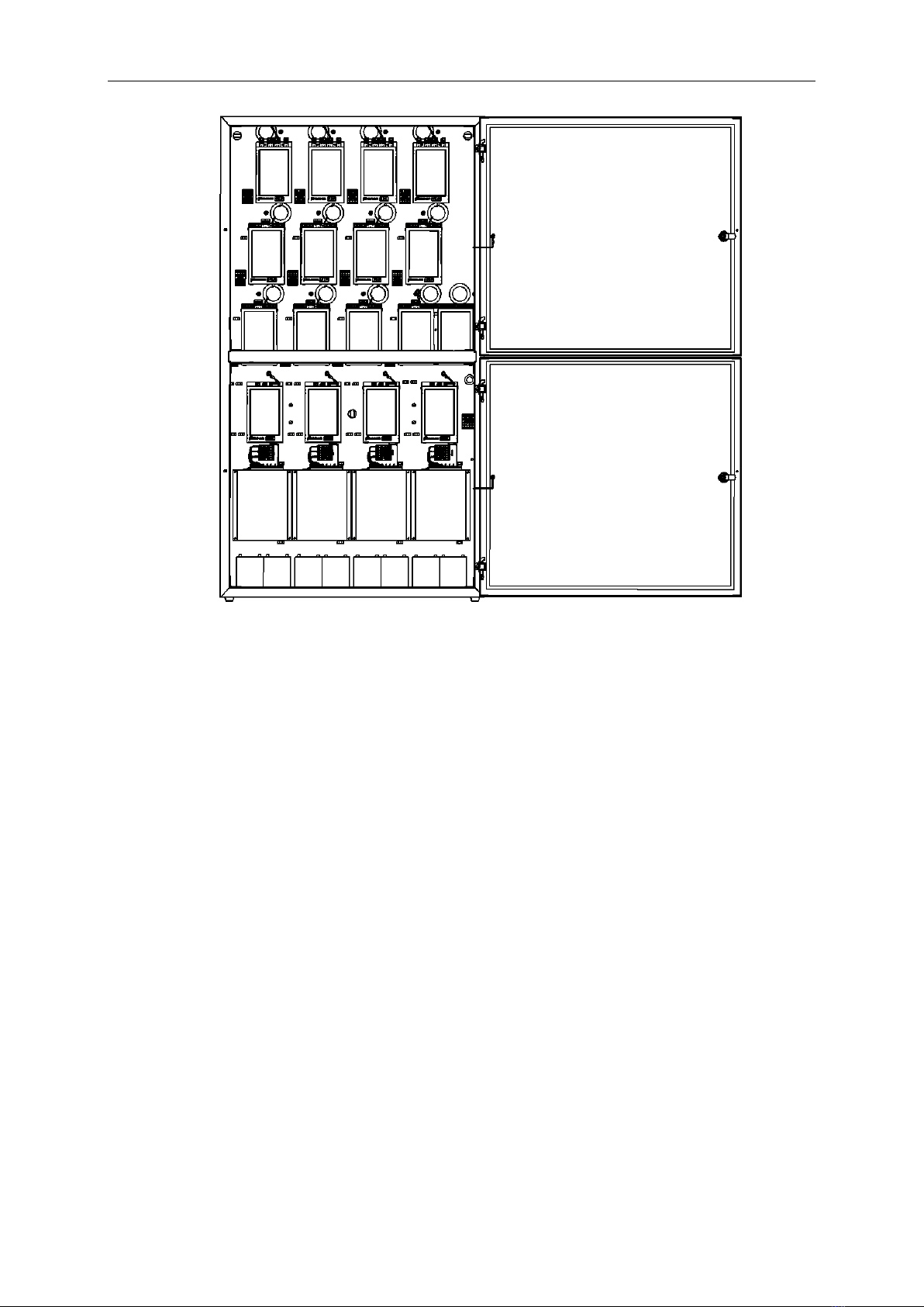
2. Control panel design and completeness ...............................Error! Bookmark not defined.
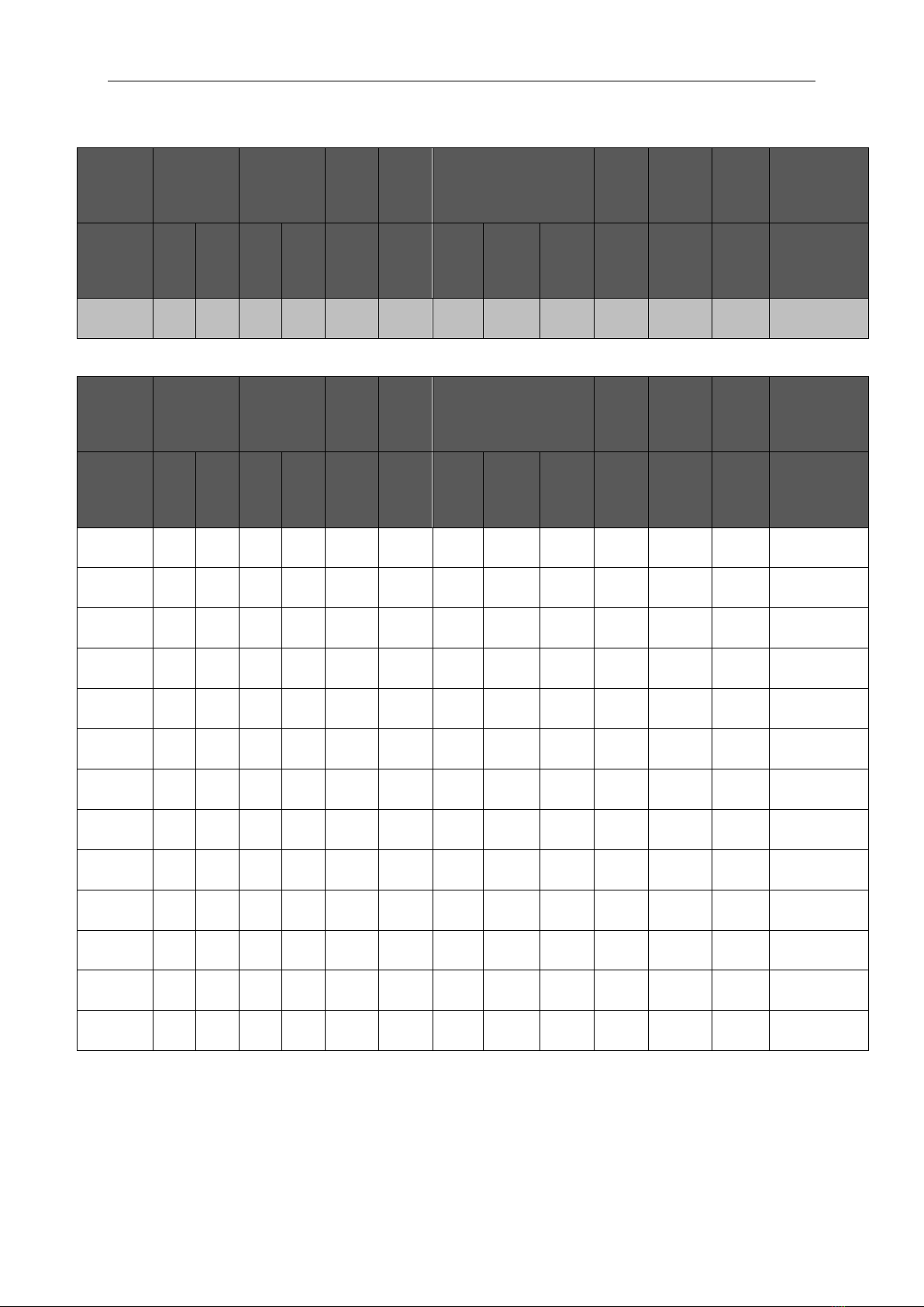
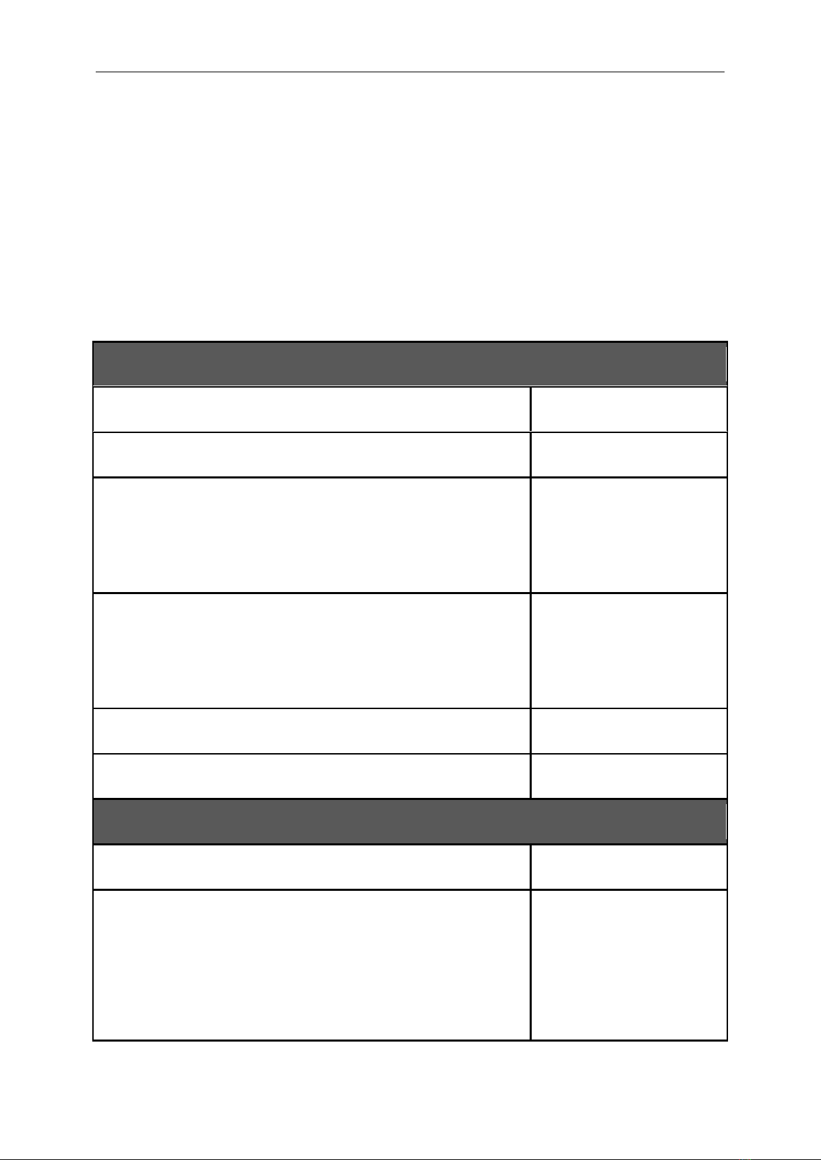
3. Technical specifications.........................................................Error! Bookmark not defined.
4. Functionality description.......................................................Error! Bookmark not defined.
4.1. General description............................................................Error! Bookmark not defined.
4.2. Control panel basic operation modes................................Error! Bookmark not defined.
4.2.1. Quiescent mode .........................................................Error! Bookmark not defined.
4.2.2. Daytime airing function..............................................Error! Bookmark not defined.
4.2.3. Alarming –fire protection devices actuation.............Error! Bookmark not defined.
4.2.4. Fault............................................................................Error! Bookmark not defined.
5. Connecting external circuits..................................................Error! Bookmark not defined.
5.1. General information...........................................................Error! Bookmark not defined.
5.2. MGS-60 module .................................................................Error! Bookmark not defined.
5.2.1. External alarm input...................................................Error! Bookmark not defined.
5.2.2. Rain/wind sensor........................................................Error! Bookmark not defined.
5.2.3. PKA alarm relay and PKU fault relay...........................Error! Bookmark not defined.
5.3. MGL-60 module..................................................................Error! Bookmark not defined.
5.3.1. Detection line .............................................................Error! Bookmark not defined.
5.3.2. Smoke exhaust button................................................Error! Bookmark not defined.
5.3.3. Fire-fighting devices output .......................................Error! Bookmark not defined.
5.3.3.1. Operation modes of output to fire protection devicesError! Bookmark not
defined.
5.3.3.1.1. OPERATION MODE - 1 ............................................Error! Bookmark not defined.
5.3.3.1.2. OPERATION MODE - 2 ............................................Error! Bookmark not defined.
5.3.3.1.3. OPERATION MODE - 3 ............................................Error! Bookmark not defined.
5.3.4. Limiting switches ........................................................Error! Bookmark not defined.
5.3.5. Airing buttons.............................................................Error! Bookmark not defined.
5.4. MPW-60 module ................................................................Error! Bookmark not defined.
5.4.1. PK1 and PK2 relays, LK1 and LK2 monitoring lines.....Error! Bookmark not defined.
5.5. MPD-60 module .................................................................Error! Bookmark not defined.
5.5.1. PK1 and PK2 relays, LK1 and LK2 monitoring lines.....Error! Bookmark not defined.
5.6. MKA-60 module .................................................................Error! Bookmark not defined.
5.7. MZU-60 module and power supply....................................Error! Bookmark not defined.
5.7.1. Basic power supply.....................................................Error! Bookmark not defined.
5.7.2. Reserve power supply ................................................Error! Bookmark not defined.
5.7.3. Reserve power supply battery discharge ...................Error! Bookmark not defined.
5.7.4. PKUZ power supply fault relay ...................................Error! Bookmark not defined.
5.7.5. Output to external devices power supply ..................Error! Bookmark not defined.
6. Control panel configuration and programming ....................Error! Bookmark not defined.
6.1. MGS-60 module configuration...........................................Error! Bookmark not defined.
6.2. MGL-60 module configuration...........................................Error! Bookmark not defined.
6.3. MPW-60 module configuration..........................................Error! Bookmark not defined.
6.4. MPD-60 module configuration...........................................Error! Bookmark not defined.

4 IK-E283-001E
6.5. MKA-60 module configuration...........................................Error! Bookmark not defined.
6.6. MZU-60 module configuration...........................................Error! Bookmark not defined.
6.7. Activations time dependences...........................................Error! Bookmark not defined.
7. Faults, events journal, system time, software versions, helpError! Bookmark not
defined.
7.1. Faults..................................................................................Error! Bookmark not defined.
7.2. Events journal.....................................................................Error! Bookmark not defined.
7.3. System time........................................................................Error! Bookmark not defined.
7.4. Software versions...............................................................Error! Bookmark not defined.
7.5. Help ....................................................................................Error! Bookmark not defined.
8. Installation.............................................................................Error! Bookmark not defined.
8.1. Control panel mounting .....................................................Error! Bookmark not defined.
8.2. Input and output circuits connecting terminals.................Error! Bookmark not defined.
9. Operation and maintenance .................................................Error! Bookmark not defined.
9.1. Proper usage guidelines.....................................................Error! Bookmark not defined.
9.2. Periodical inspection and maintenance rules....................Error! Bookmark not defined.
10. Packing, storing, transportation............................................Error! Bookmark not defined.
10.1. Packing ...............................................................................Error! Bookmark not defined.
10.2. Storing ................................................................................Error! Bookmark not defined.
10.3. Transporting.......................................................................Error! Bookmark not defined.
11. Instructions on the control panel proper functioning inspection after installation ....Error!
Bookmark not defined.

IK-E283-001E 5
1 INTRODUCTION
1.1.Documentation contents
The subject matter of this Operation and Maintenance Documentation (OMD) is the UCS 6000
universal control panel (Fig. 1.1, Fig. 1.2), which is a part of the POLON 4000 system.
The OMD is intended for designers, installers and maintenance technicians of the UCS 6000 universal
control panel. The OMD contains information necessary for the panel proper installation,
programming, servicing and operation.
1.2.Control panel application
The UCS 6000 universal control panel (hereinafter referred to as ‘the panel’) is a microprocessor-
based device designed for actuation of fire protection devices, used for gravitation or mechanical
smoke ventilation (smoke exhaust dampers, fire dampers, etc.) and daytime airing.
The panel unit is adapted to work in closed premises of low dust contents, temperature ranging
between - 10 °C and + 55 °C and relative air humidity up to 80% at + 55 °C.
1.3. Safety conditions
1.3.1 Electric shock protection
The UCS 6000 universal control panels are ranked as 1st protection class devices and can be used only
with additional protection against electric shocks, i.e. mains earthing or protective grounded
installation.
230 V/50 Hz mains supply circuits insulation is reinforced and resits 2800 V voltage test. Low-voltage
circuits (below 42 V) insulation is able to resist test voltage of 700 V DC.
1.3.2 Installation and equipment safety
Wire installation should be made using cables of the required fire resistance and should be properly
protected in passages through fire zone boundaries.
In order to avoid undesirable interaction, a required distance between the low-voltage installation
and a power installation and a lightning protection system should be maintained.
From the system interference resistance, it is recommended to utilise protective grounding.
Reserve power supply batteries should be connected to the panel at the final stage of the
installation.
The panel components are heat sensitive. The maximum ambient temperature should not exceed +
55 °C. Air humidity in the premises where the panel operates should not exceed 80 %. No objects
should be placed on the panel, which should be also prevented from water penetration into the
device.
1.3.3 Repair works and maintenance

6 IK-E283-001E
Maintenance works and periodical inspections should be executed by skilled personnel employed by
companies authorised or trained by Polon-Alfa. Any repair works must be carried out by the
manufacturer. Polon-Alfa bears no responsibility for the operation of any apparatus being serviced or
repaired by unauthorised personnel.
1.3.3 Fuse replacement
In the event of fuse replacement, an equivalent fuse should be used: of the appropriate type and
nominal value. The corresponding data (types and nominal values) are contained in point 9.1 of this
manual.
Fig. 1.1 UCS 6000 control panel up to 16 A

IK-E283-001E 7
Fig. 1.2 UCS 6000 control panel from 32 A to 64 A
2 CONTROL PANEL DESIGN AND COMPLETENESS
The UCS 6000 universal control panel is a module-type microprocessor-based device which combines
functions of a fire detecting and alarm control panel and a universal smoke exhaust controller
furnished with a daytime airing option.
The panel consists of the following functional modules and batteries:
- MGS-60 4A module –a main controller module (with one MGL module enclosed, 4 A version);
- MGS-60 8A module - a main controller module (with one MGL module enclosed, 8 A version);
- MZU-60 module - a universal power supply module (16 A/24 V);
- MGL-60 4A module –a group-line module, 4 A version;
- MGL-60 8A module –a line-group module, 8 A version;
- MPW-60 module –a high-voltage relay module (2 x PK 5 A/230 V, 2 x LK 24 V);
- MKA-60 module –an addressable communication module (POLON 4000 system);
- MPD-60 module –an auxiliary relay module (2 x PK 1 A/24 V, 2 x LK 24 V);

8 IK-E283-001E
- SP-150-27.5PLA module –a power supply device module 150 W (5 A);
- SP-240-27.5PLA module –a power supply device module 240 W (10 A);
- SP-500-27.5PLA module –a power supply device module 500 W (20 A); ‘1’ execution (SP1), ‘2’
execution (SP2);
- 7.2 —9 Ah battery –2 pcs per each universal power supply module.
Table 2.1. Maximum quantity of modules in the UCS 6000 panel
MGS 60
(+ MGL 60)
MGL
60
MZU
60
MPW
60
MPD
60
MKA
60
SP
150
SP
240
SP1
500
SP2
500
AKU
7.2 –9 Ah
1
7
4
4
1
1
1
1
1
4
8
Table 2.2. Basic assembling –casing up to 16 A (400 x 400 x 160)
Version
MGS
60
MGL
60
MZU
60
MPW
60
POWER SUPPLY UNIT
AKU
MPD
60
MKA
60
Current
4A
8A
4A
8A
16A
pcs
SP
150
SP
240
SP1
500
pcs
pcs
pcs
1
1
-
-
-
1
1 •
1
-
-
2
1 •
1 •
4A (1x4A)
2
1
-
1
-
1
-
-
1
-
2
1 •
1 •
8A (2x4A)
3
-
1
-
-
1
1 •
-
1
-
2
1 •
1 •
8A (1x8A)
4
-
1
-
1
1
-
-
-
1
2
1 •
1 •
16A (2x8A)
Table 2.3. Special assembling (to be ordered) –casing up to 16 A (400 x 400 x 160)
Version
MGS
60
MGL
60
MZU
60
MPW
60
POWER SUPPLY UNIT
AKU
MPD
60
MKA
60
Current
4A
8A
4A
8A
16A
pcs
SP
150
SP
240
SP1
500
pcs
pcs
pcs
5
1
-
-
-
1
1
1
-
-
2
1 •
1 •
4A (1x4A)
6
-
1
-
-
1
1
-
1
-
2
1 •
1 •
8A (1x8A)
• –optional

IK-E283-001E 9
Table 2.4. Basic assembling –casing 32 A –64 A (1150 x 630 x 190)
Version
MGS
60
MGL
60
MZU
60
MPW
60
POWER SUPPLY UNIT
AKU
MPD
60
MKA
60
Current
4A
8A
4A
8A
16A
pcs
SP2
500
pcs
pcs
pcs
7
-
1
-
3
2
-
-
-
2
4
1 •
1 •
32A (4x8A)
Table 2.5. Special assembling (to be ordered) –casing 32 A –64 A (1150 x 630 x 190)
Version
MGS
60
MGL
60
MZU
60
MPW
60
POWER SUPPLY UNIT
AKU
MPD
60
MKA
60
Current
4A
8A
4A
8A
16A
pcs
SP2
500
pcs
pcs
pcs
8
-
1
-
5
3
-
-
-
3
6
1 •
1 •
48A (6x8A)
9
-
1
-
7
4
-
-
-
4
8
1 •
1 •
64A (8x8A)
10
-
1
-
4
3
3 •
-
-
3
6
1 •
1 •
40A (5x8A)
11
-
1
-
6
4
4 •
-
-
4
8
1 •
1 •
56A(7x8A)
12
-
1
-
3
2
1
-
-
2
4
1 •
1 •
32A (4x8A)
13
-
1
-
3
2
2
-
-
2
4
1 •
1 •
32A (4x8A)
14
-
1
-
5
3
1
-
-
3
6
1 •
1 •
48A (6x8A)
15
-
1
-
5
3
2
-
-
3
6
1 •
1 •
48A (6x8A)
16
-
1
-
5
3
3
-
-
3
6
1 •
1 •
48A (6x8A)
17
-
1
-
7
4
1
-
-
4
8
1 •
1 •
64A (8x8A)
18
-
1
-
7
4
2
-
-
4
8
1 •
1 •
64A (8x8A)
19
-
1
-
7
4
3
-
-
4
8
1 •
1 •
64A (8x8A)
20
-
1
-
7
4
4
-
-
4
8
1 •
1 •
64A (8x8A)
• –optional
The MPD-60 and MKA-60 optional modules (ordered separately) are installed on the MGS-60 main
controller module and interoperate with every equipment version.

10 IK-E283-001E
The MPW-60 module (‘5’ - ‘6’, ‘12’- ‘20’versions) is optional and is supplied separately.
All highlighted equipment assembly versions are treated as basic. Other variants are available on
request.
The SP-500-27.5PLA power supply device is available in two variants: SP1 (for the housing up to 16 A
400 x 400 x 160) and SP2 (for the housing from 32 A to 64 A 1150 x 630 x 190).
3. TECHNICAL SPECIFICATIONS
Table 3.1
INPUT PARAMETERS
Basic power supply voltage
230 V AC + 10 % - 15 %
Basic power supply voltage freequency
47 ... 63 Hz
Maximum mains voltage draw
Casing up to 16 A
Casing from 32 A to 64 A
< 7 A
< 28 A
Reserve power supply source
Casing up to 16 A
Casing from 32 A to 64 A
Max.
2 x 12 V / 7.2 –9 Ah
8 x 12 V / 7.2 –9 Ah
Current draw from batteries during quiescent mode
< 120 mA
Current draw from POLON 4000 system addressable detection line
< 0,6 mA
OUTPUT PARAMETES
Control panel operation voltage
24 V DC + 25 % - 25 %
Direct current available from mains power supply unit:
- 150W power supply unit
- 240W power supply unit
- 500W power supply unit
5 A
10 A
20 A

IK-E283-001E 11
INPUT PARAMETERS
MGS-60 MODULE
External alarm line
2 x 120 Ω
> 100 kΩ
5,6 kΩ ± 5 %; 0,5 W
Maximum line resistance:
Line insulation resistance:
Line end-of-line resistor:
Rain and/or wind sensor power supply:
24 V DC + 25 % - 25 %
0,5 A
Output voltage:
Output current:
Rain and/or wind sensor signal monitoring line
2 x 100 Ω
> 100 kΩ
Maximum line resistance:
Line insulation resistance:
PKA alarm relay
1 A / 24 V DC
programmable
YES
NO/NC terminal current-voltage load:
Top –activation delay time:
Continuity monitoring (adjustable and programmable):
PKU fault relay
1 A / 24 V DC
NO/NC terminal current-voltage load:
MGL-60 MODULE
Main input

12 IK-E283-001E
Input voltage:
Output current:
Operation modes (programmable):
T1 –activation delay time:
T2 –activation time:
T3 –activation break time:
Continuity monitoring (programmable):
24 V DC + 25 % - 25 %
4 A or 8 A
3
programmable
programmable
programmable
YES
Limit switch status monitoring lines
2 x 100 Ω
> 100 kΩ
YES
YES
Maximum line resistance:
Line insulation resistance:
Status monitoring (programmable):
Continuity monitoring (programmable):
OPEN CLOSE airing push buttons lines
2 x 100 Ω
> 100 kΩ
Maximum line resistance:
Line insulation resistance:
Conventional detection line
32
2 x 120 Ω
> 100 kΩ
5,6 kΩ ± 5 %; 0,5 W
2 mA
7 mA
Number of detectors (40 model range) in line:
Maximum line resistance:
Line insulation resistance:
End-of-line resistor:
Maximum quiescent mode detectors current:
Total quiescent mode line current max.:
PO-6x manual smoke exhaust push buttons line
8
Maximum numer of push buttons in line:

IK-E283-001E 13
Maximum line resistance:
Line insulation resistance:
ACTUATION and RESET line end-of-line resistor:
Maximum quiescent mode current of 1 push button:
Quiescent mode line total current:
6 x 120 Ω
> 100 kΩ
5,6 kΩ ± 5 %; 0,5 W
12 mA
< 100 mA
MPW-60 MODULE
PK1 i PK2 relays
5 A/ 230 V AC
4
5
programmable
programmable
programmable
programmable
NO/NC terminal current-voltage load:
Operation modes (programmable):
Activation variants (programmable)
T1 –activation delay time:
T2 –activation time:
T3 –activation break time:
N –controlling impulses number
PK1 and PK2 relayactuation LK1 and LK2 monitoring lines
2 x 100 Ω
> 100 kΩ
Maximum line resistance:
Line insulation resistance:
MPD-60 MODULE
PK1 i PK2 relays

14 IK-E283-001E
NO/NC terminal current-voltage load:
Operation modes (programmable):
Activation variants (programmable)
T1 –activation delay time:
T2 –activation time:
T3 –activation break time:
N –controlling impulses number
1 A/ 24 V DC
4
5
programmable
programmable
programmable
programmable
LK1 i LK2 monitoring lines
3
2 x 100 Ω
> 100 kΩ
Operation modes (programmable):
Maximum line resistance:
Line insulation resistance:
MZU-60 MODULE
PKUZ power supply fault relay
1 A / 24 V DC
NO/NC terminal current-voltage load:
Output to external devices power supply
24 V DC + 25 % - 25 %
0,5 A
Output voltage:
Output current:
ENVIRONMENTAL PARAMETES
Transportation temperature
- 25 °C ... + 55 °C
Operation temperature
- 10 °C ... + 55 °C

IK-E283-001E 15
Allowable operation relative humidity
80 % at + 55 °C
DESIGN PARAMETES
Ingress protection
IP 30
Dimensions (without fixings and legs) L x H x G
Casing up to 16 A
Casing from 32 A to 64 A
400 x 400 x 160 mm
1150 x 630 x 190 mm
Mass (without batteries)
Casing up to 16 A
Casing from 32 A to 64 A
< 8 kg
< 40 kg
INTEROPERATION WITH OTHER DEVICES
Certified fire-fighting dampers drives powered by 24 V DC
Certified electromagnets (holders) forfire-fighting doors powered by 24 V DC
POLON 4000 system fire detecting and alarm control panels:
POLON 4100
POLON 4200
POLON 4500
POLON 4900
IGNIS 1000 system fire detecting and alarm control panels
CONTROL PANEL OPERATION
Variable, program performed depending on premises fire scenario requirements

16 IK-E283-001E
4. FUNCTIONALITY DESCRIPTION
4.1.General description
The UCS 6000 universal control panel is designed for actuation of fire protection devices, used for
gravitation or mechanical smoke ventilation (smoke exhaust dampers, fire dampers, etc.) and it
enables:
-fire (smokiness) detection;
-automatic or manual actuation of fire protection devices installed in smoke exhaust systems;
-acoustic and optical signalling of the devices operation modes (alarm, fault);
-automatic monitoring of actuation of fire protection devices (servomotors, electromagnets,
ventilators, etc.) composing smoke exhaust system;
-automatic monitoring of its own modules and the panel circuits;
-basic information transmission to master control systems (e.g. the POLON 4000 system, the
IGNIS 1000 system or others) about an alarm mode, faults, current fire protection and
executive devices status.
The UCS 6000 control panel can work individually as single- or multi-zone universal smoke exhausting
controller or in addressable detection lines/loops of the POLON 4000 system fire alarm panels.
The control panel (Fig. 4.1) is equipped with:
-the MGS-60 module (x1):
-a supervised line that receives an alarm signal from an external fire detection and alarm
control panel,
-a rain and/or wind sensor power supply line,
-a rain and/or wind sensor signal receiving line,
-the PKA supervised alarm relay (circuit continuity),
-the PKU fault relay.
-the MGL-60 module (x8):
-a conventional detection line (40 model range detectors),
-a conventional line for manual smoke exhaust push buttons (PO-6X model range
buttons),
-a supervised main output, universal for control and power supply of fire protection
devices (servomotors and fire/smoke damper drives, fire zone separators
electromagnets, etc.),
-monitoring lines to monitor the status of end contacts installed in fire protection devices,
which are controlled and power supplied by the main output,
-lines that receive signals from ventilation push buttons (OPEN, CLOSE)
-the MPW-60 module (x4):
-2 programmable PK1 and PK2 relays, high voltage type (5 A / 230 V),
-2 supervised programmable LK1 and LK2 (24 V) monitoring lines;
-the MPD-60 module (x1):
-2 supervised programmable PK1 and PK2 (1 A / 24 V) relays,
-2 supervised programmable LK1 and LK2 (24 V) monitoring lines;
-the MKA-60 module (x1):
-a communication line for POLON 4000 system (addressable detection line);

IK-E283-001E 17
-the MZU-60 module (x4):
-the PKUZ (1 A/24 V) power supply fault relay,
-a supervised output for external devices power supply (0.5 A / 24 V).
Fig. 4.1 Function bloc diagram of smoke exhausting system with UCS 6000 panel

18 IK-E283-001E
A fire is detected by a conventional detection line with 40 model range detectors being installed. The
line is able to program an alarm variant with preliminary reset (60 s) in order to eliminate accidental
actuations.
In the smoke exhaust controlling section, a fire protection devices actuation is possible only as a
result of:
-actuation of a detector in a conventional detection line;
-actuation of a smoke exhaust manual push button;
-an alarm signal occurrence from an external fire alarm control panel, e.g. IGNIS 1000,
-the POLON 4000 system control panel command.
Initiation of the smoke exhaust procedure –pursuantly to a programmed fire scenario for a given
object –takes place upon receipt of an actuation signal. Air venting buttons are disabled and signals
coming from the rain and/or wind detector are ignored.
A detailed description of particular inputs and outputs operation together with the configuration and
programming process are included in points 5 and 6.
4.2. Control panel basic operation modes
4.2.1. Quiescent mode
In a quiescent (supervision) mode only a green indicator DOZOROWANIE is lit on the PO-6x model
range manual smoke exhaust buttons connected to the MGL-60 module, what signals an activation
and proper operation of the modules (of the control panel).
The control panel MPD-60 and MPW-60 modules execution relays are inactive excluding the PKU
(MGS-60) general fault relay which is an active mode (NO position).
4.2.2. Daytime airing function
The quiescent mode enables performance of daytime airing –ventilation executed using windows
and ventilation dampers.
In case the MGL-60 module main output is programmed in OPERATION MODE 1 (a drive or two-
direction actuator), it is possible to open and close the windows and ventilation dampers with air
venting push buttons.
The air venting push buttons can work in two modes:
1 –as long as the button is pressed –opening or closing of the windows and ventilation dampers;
2 –the button single push –complete opening or closing of the windows and ventilation dampers.
Additionally it is possible to set airing time parameters (point 6.2):
Tp1 - window or damper opening time (button mode 2),
Tp2 –time of automatic complete closing of the window or ventilation damper (button mode 1 and
2).

IK-E283-001E 19
A detailed description of the airing buttons connection and programming is included in points 5.3.5
and 6.2.
The daytime ventilation process can be additionally supported by weather automation.
In case, after a rain and/or wind detector connecting and programming, unfavourable weather
conditions occur (too strong wind or heavy rain), the MGL-60 modules opening buttons are disabled.
If a window or damper is open for daytime ventilation, they automatically close when a rain or wind
signal is received. In the case of fire alarm occurrence, the rain and/or wind sensor signal is disabled.
In the case of mains basic power supply outage, the airing push buttons are also disabled and it is
only possible to close once the dampers or windows that are already opened.
4.2.3. Alarming –fire protection devices actuation
When a fire danger or smokiness is detected (detectors in alarm mode, actuated manual smoke
exhaust push button, external alarm, command from the POLON 4000 control panel), a fire alarm is
indicated in the UCS 6000 control panel.
The alarm is signalled with a flashing light of the FIRE indicator in the PO-6X model range manual
smoke exhaust push buttons.
The OK indicator in the PO-6X model range manual smoke exhaust push buttons is turned off.
The PKA alarm relay is activated. The weather automation and the MGL-60 module air venting push
buttons are disabled.
The control panel internal acoustic signalling is switched on (if it is active –see point 5.2), which can
be silenced with the internal ACKNOWLEDGEMENT push button located on the MGS-60 module or
with the external ACKNOWLEDGEMENT push button (points 5.5.1 and 6.4). Upon acknowledgement,
the FIRE indicator is lit permanently. After each new alarm from another source (e.g. external alarm
after an alarm from a detector) the flashing FIRE indicator switches once more and the control panel
internal acoustic signalling triggers but it can be silenced again.
Once the UCS 6000 control panel enters a fire alarm state, an automatic smoke exhausting procedure
is initiated pursuant to a programmed scenario (e.g. actuation with appropriate T1, T2, T3 time
parameters of the MGL-60 main module outputs (points 5.3.3 and 6.2). The modules are connected,
among other devices, with smoke exhaust dampers, activation of the PK1 and PK2 programmable
relays of the MPW-60 modules (points 5.4.1 and 6.3) and the MPD-60 modules (5.5.1 and 6.4) that
control ventilators, air curtains and so on.
To minimize warning devices false activation probability, the control panel is furnished with an
option to settle a variant with initial detector signal reset.
In this variant the control panel automatically clears the first detector actuation without triggering an
alarm mode. A renewed detector activation results in a fire alarm evoking. If the detector in a
detection line is not actuated again within 60 s, the control panel treats the previous actuation as

20 IK-E283-001E
false and returns to the quiescent mode as before the first activation. The manner of switching over
the MGL-60 modules detection lines to the above variant is described in points 5.3.1 and 6.2.
The UCS 6000 control panel alarm mode reset and return to a quiescent mode can be achieved:
-using the internal RESET push button placed on the MGS-60 module,
-using the RESET push buttons inside the PO-62 and PO-63 manual smoke exhaust push
buttons,
-using the external RESET push button (points 5.5.1 and 6.4),
-at the POLON 4000 system control panel.
Such reset is only effective when there is no fire factor in the automatic fire warning devices vicinity,
no external alarm signal and no FIRE signal from a manual smoke exhaust button.
4.2.4. Fault
Any detected fault is signalled optically and acoustically.
Optically a fault is signalled by:
-flashes of the FAULT collective diode located on the MGS-60 module, which indicate faults
within the entire smoke exhaust installation,
-flashes of the FAULT diode located on the PO-6x smoke exhaust manual button connected to
the first MGL-60 module and configured for collective signalling (points 5.3.2. and 6.2),
-flashes of the FAULT diode located on the PO-6x smoke exhaust manual buttons connected
to the MGL-60 modules (points 5.3.2. and 6.2), which indicate faults within a given module
installation.
A damage is signalled acoustically by a repeated signal of the internal acoustic signalling device
(MGS-60).
The acoustic signal can be silenced with the internal ACKNOWLEDGEMENT button located on the
MGS-60 module or with the external ACKNOWLEDGEMENT button (points 5.5.1 and 6.4). After
conformation, the FAULT signalling diode is lit steadily.
A fault optical and acoustic signalling reset is executed automatically after the fault removal.
The smoke exhaust system fault readout is possible using an application for the UCS 6000 controller
configuration (UCSKonfigurator).
5. CONNECTING EXTERNAL CIRCUITS
5.1.General information
The UCS 6000 control panel modules are fitted with a range of universal inputs and outputs in order
to connect external smoke exhaust installations. The operation mode of the inputs and outputs along
with the time criteria is programmed with the use of the application for the UCS 6000 controller
configuration (UCSKonfigurator) –point 6.
All electric connections should be done in accordance with applicable regulations regarding fire and
mechanical resistance, and observing all parameters (resistance) specified in table 3.1 point 3.
Other manuals for POLON 4000 Series
5
This manual suits for next models
1
Table of contents
Other Polon-Alfa Fire Alarm manuals
Popular Fire Alarm manuals by other brands

Panasonic
Panasonic 6362 quick start guide

Radionics
Radionics D7024 operating instructions

Firesense
Firesense DA Series Operation, installation & programming manual

Pro-tec
Pro-tec 6000/LOOP/REPEATER Installation and user guide

thefirebeam
thefirebeam firebeam user guide

UniPOS
UniPOS FD3050 instruction manual