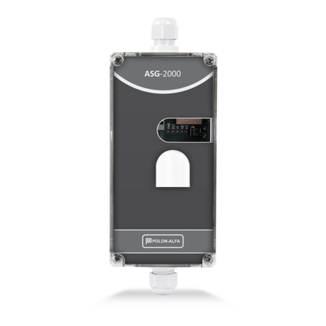
Polon-Alfa PSG-6000 Manual

1 IK-E363-001
ADDRESSABLE
GAS DETECTORS
TYPE PSG-6000
Installation and Maintenance Manual
IK-E363-001
Edition II

IK-E363-001 2
Addressable gas detectors type PSG-6000, subject to these Instructions, meet the essential
requirements of the following Regulations of the European Parliament and of the Council (EU) as well
as European Union directives:
EMC Directive (EU) 2014/30/EU on electromagnetic compatibility.
The Declaration of Conformity No. 1/E366/2017/PL was issued for addressable gas detectors type PSG-
6000.
The Declaration of Conformity is available at www.polon-alfa.pl .
Prior to starting assembly and operation, please read the contents of this manual.
Failure to follow the instructions of this manual may be dangerous or cause violation of applicable
regulations.
The Polon-Alfa manufacturer is not liable for damages resulting from use contrary to this instruction.
A worn out product, not suitable for further use, should be
transferred to one of the entities dealing with the collection of waste
electrical and electronic equipment.
Note –the manufacturer reserves the right to introduce changes to this instruction

3 IK-E363-001
1. INTENDED APPLICATION.
Detectors type PSG-6000 are designed for the detection of flammable and toxic gases in public
facilities, especially in underground garages and boiler rooms. It has a replaceable sensor module with
3 alarm thresholds. Addressable gas detectors type PSG-6000 operate on the detection lines of the
CDG6000.
!!! PLEASE NOTE
PSG-6000 type detectors are not intended for use in potentially explosive atmospheres.
Thanks to the built-in temperature compensation, detectors can work in changing environmental
conditions.
Information about the installed sensor module together with the alarm threshold values can be found
on the detector housing.
PSG-6000 detectors are equipped with short-circuit isolators.
Table 1: Selection of PSG-6000 detectors.
Detected gas
CNG (natural gas)
(selective methane)
LPG
(propane butane)
CO
(carbon monoxide)
Type
PSG-6001
PSG-6002
PSG-6003
PSG-6103
Sensor module
MSG-6001
MSG-6002
MSG-6003
MSG-6003
Type of sensor
semiconductor
semiconductor
electrochemical
electrochemical
Sensor supply
external 9÷30 V
external 9÷30 V
external 9÷30 V
from the detection
line
2. THREATS RELATED TO GASES.
CO - carbon monoxide - colourless and odourless gas, undetectable by the senses. Slightly lighter than
air, very easily mixed with it. Carbon monoxide as a product of incomplete combustion is practically
always present in exhaust gases of motor vehicles and in boiler rooms. It is perfectly absorbed into the
body (better than oxygen) permanently binding to haemoglobin, which may result in serious hypoxia.
LPG (autogas) - the most popular gas fuel in vehicles with an internal combustion engine. A mixture of
combustible hydrocarbons, mainly propane and butane. The lower explosion limit of butane is 1.4%
and propane 1.7%. It is much heavier than air, which means that it will be lying down in all depressions
of the area, basements, car inspection pits, etc. The danger associated with LPG is primarily its
Table 2: The effect of carbon monoxide on humans according to CIOP-PIB1.
The concentration of CO in
the air
ABSOPTION TIME AND observed SYMPTOMS OF POISONING
~ 200 ppm
slight headache after a few hours
~ 400 ppm
headache, nausea, vomiting, muscle weakness, malaise after 1 to 2 hours
~ 800 ppm
circulatory collapse, loss of consciousness after 2 hours
~ 1600 ppm
circulatory collapse within 20 minutes, risk of DEATH after 2 hours
~ 3400 ppm
collapse after 5-10 minutes, the risk of DEATH after 30 minutes
~ 7000 ppm
collapse after 1-2 minutes, risk of DEATH after 10 -15 minutes
~ 13000 ppm
DEATH after 1 to 3 minutes!
1NOTE: for CO 1% vol. = 10,000 ppm = 8,600 mg/m3

IK-E363-001 4
explosiveness.
CNG (compressed natural gas) - an increasingly popular and cheap fuel for delivery vehicles and public
transport. The main component is methane - gas much lighter than air, which means that it can lie
under the ceiling of the room. The lower explosion limit for methane is 4.4%.
3. TECHNICAL DATA.
Table 3: Technical parameters.
Parameter
PSG-600x
PSG-610x
Power supply voltage.
external 9 ÷ 30 V DC
from the detection line 16,5 V ÷ 24,6
V
from the detection line 16,5 V ÷ 24,6
V
Power consumption
max 30 mA @ 12 V
max 15 mA @ 24 V
non-applicable
Current consumption from the detection line
< 150 µA
< 250 µA
Alarm thresholds
PSG-6001: A1 = 10% A2 = 20% A3 = 30% LEL methane (selective)
PSG-6002: A1 = 10% A2 = 20% A3 = 30% LEL propane-butane (50/50)
PSG-6x03: A1 = 30 ppm CO (TWA 15 min.) A2 = 60 ppm CO (TWA 15 min.) A3
= 150 ppm (exceeded for at least 60 s) according to PN-EN 50545-1
Gases interfering the measurement
PSG-6001: hydrogen, ethanol, oxygen deficiency
PSG-6002 : methane, hydrogen, ethanol, oxygen deficiency
PSG-6x03 : hydrogen, ethanol at low extent
Working conditions
-20 ÷ 50°C humidity 10-90%
The storage conditions
0 ÷ 40°C humidity 10-80%
Protection level
IP54 (in the recommended mounting position)
Housing material
ABS/PC
Cable connectors (cable diameter)
M12 gland (3÷6.5 mm)
Dimensions (with connectors)
160x124x68 mm
120x124x68 mm
Mass
<0.3 kg
<0.25 kg
Frequency of service inspections
Recommended in 3 months (maximum 12 months)
Sensor life time.
10 years
4. STRUCTURE DESCRIPTION.
Fig. 1,2 shows the interior of the detectors PSG-6000 and PSG-6100, respectively. PSG-6000 detectors
work with interchangeable MSG-6000 type sensor modules. The detector has a spring connection that
allows the use of cables such as wire and cord with a diameter of 0.25 to 1.5 mm2(up to 1 mm2when
using collets). In detectors of the PSG-6000 type, the detection line system is insulated which allows to
connect the detector power from any source, moreover it is possible to supply detectors on the
detection line from various sources. In PSG detectors - 6001 and PSG-6002 on the sensor module there
is a cover with a dust filter that protects not only against dust, but also small insects. In the PSG
detector - 6x03 the sensor is sealed directly to the ventilation element.

5 IK-E363-001
Figure 1 The interior of the PSG-6000 detector.
magnetic field sensor location
sensor module
sensor cover
sensor module power
terminals
detection line terminals

IK-E363-001 6
Figure 2 The interior of the PSG-6100 detector.
5. FUNCTIONAL DESCRIPTION.
Detectors in their principle of operation use the phenomenon of gas diffusion in the environment. The
ventilation element allows gas to enter the detector and reach the sensor. The microprocessor
measurement system continuously analyses the concentration of the measured gas and compares it
with the value of the appropriate alarm threshold. In the case of alarm thresholds expressed in
instantaneous values, a false alarm filter (shorter than 15s) has been added. The measuring system
also performs temperature compensation allowing the use of detectors in a wider temperature range.
After connecting the power supply, the detector is in the sensor's 60 second warming state during
which the sensor pre-conditioning is conducted. Semiconductor sensors achieve full measurement
efficiency after at least 48 hours of uninterrupted power supply.
The built-in short circuit isolator allows detection of faults and damage to the installation. In the case
of using a loop line, damage to the line in one place does not disconnect the detectors from the central
unit.
The detector's alarm condition is signalled by a pulsed, red LED light. The indicator enables quick
detection of the alarming detector and is helpful in periodically checking the detector's operation. The
detector fault condition is indicated by a pulsed, yellow LED light. The green POWER LED indicates the
operation of the detector. In detectors PSG-6100 it flashes signalling the correct operation of the
detector. In the PSG-6000 detectors, the POWER diode is connected to the sensory module, signalling
the correct voltage supply to the sensor module, in addition, short flashes of this diode signal the state
of heating of the sensor. Short stops in lighting signal detection of a small amount of gas detected,
which may be helpful during periodic inspection.
detection line terminals
sensor module
magnetic field sensor location

7 IK-E363-001
6. INSTALLATION OF DETECTORS.
6.1. Place of installation.
The place of installation has a significant impact on the detector's work. The detector should be
mounted:
•as close as possible to the potential source of gas - no more than 9 m,
•away from ventilation openings, doors or windows,
•in a place with free flow of ambient air,
•in a place with no sun exposure, far from heat sources,
•in a place not impacted by mechanical damage, vibrations and strong electromagnetic fields,
•in a place not impacted by direct influence of outside air, water vapour, liquids and car exhaust,
exhaust gases from furnaces and dust.
CO detectors should be mounted at a height of about 1.5-2 m (i.e. at the height of the head of a person
of an average height).
LPG detectors should be mounted at a height of 15 cm away from the hollows in the ground.
CNG detectors should be mounted at a height not lower than 30 cm below the ceiling or on the ceiling.
6.2. Mounting position.
Detectors of the PSG-6000 series are recommended to be installed in a vertical position with the gas
inlet down, this position guarantees the best protection against dust and splashes. In the case of
methane detectors, due to the mounting height, a horizontal position (increased susceptibility to dust
accumulation in the gas inlet element) or ceiling mounting is possible although not recommended.
Installation with the gas inlet directed upwards is not allowed, in this position the detector is exposed
to splashes of water and excessive accumulation of dust in the gas inlet. Mounting positions are shown
in Figure 4.
For propane-butane detectors, due to the low mounting height in places exposed to mechanical
damage, it is recommended to use a suitable cover.
Figure 3 Mounting positions of PSG-6000 detectors.
RECOMMENDED VERTICAL POSITION
MOUNTING POSITIONS
HORIZONTAL POSITION
NOT RECOMMENDED (BUT ALLOWED)
VERTICAL POSITION
UPSIDE DOWN –
NOT ALLOWED
ASSEMBLY ON THE CEILING:
PSG 6001 –ALLOWED
PSG 6002 –NOT ALLOWED
PSG 6XO3 –NOT RECOMMENDED

IK-E363-001 8
6.3. Detector installation.
!!! PLEASE NOTE
All work related to the installation of detectors should be carried out with the
disconnected power supply.
Before mounting, check the validity of the calibration certificate.
Remove the detector cover and the sensor module to protect it from dust. Mount the detector to the
ground with 4 wall plugs.
Terminal block connectors allow the use of multiple wire cables like wire and cord with a cross section
between 0.25 and 1.5 mm2(1 mm2in the case of the use of collets). The diameter of the cable is limited
by the cable glands used and amounts to 3 ÷ 6.5 mm. The cable ends must be insulated to a length of
8 mm.
After connecting the power supply and heating all sensors, you can perform the installation test
according to the procedure 8.1. After a positive result, you can install the detector covers making sure
that the sensor covers are mounted and located in the correct position. Lack of the sensor cover
reduces the protection of the enclosure to IP43 and the work of the detector without the sensor cover
is forbidden.
The detector connection diagram is shown in Figure 5.
Figure 4 Connection diagram of the detector.
7. OPERATION AND SERVICE CONDITIONS.
In accordance with the Regulation of the Minister of Interior and Administration of April 21, 2006 on
the fire protection of buildings and other construction facilities 2006 No. 80, item 563, technical
inspection and maintenance of gas detection systems ought to be conducted at least once a year.
Periodic inspection is recommended to be carried out once every 3 months and after the occurrence
detection line input/output
9-30 v power supply or
of another detector
9-30 v power supply or
of another detector

9 IK-E363-001
of:
•extreme operating conditions, i.e. high dust level, temperatures beyond the allowable range,
high concentration of detected gas,
•long-lasting alarm condition,
•after a long power supply interruption,
•after renovation work.
Periodic inspection consists in:
•checking the patency of the gas sensor cover and the condition of the seals,
•periodic testing of detection functions, see 8.2.
As semiconductor sensors increase their sensitivity over time, it is recommended to calibrate the
sensor at least once every 3 years and after too frequent reactions to too low gas concentrations.
Electrochemical sensors decrease their sensitivity over time, and the long term of very low humidity
level or very high humidity level will have an effect on changing the sensitivity. It is recommended to
calibrate devices at least every 3 years. The expiration of the calibration validity period is indicated by
a fault.
In the case of renovation works, PSG-6000 detectors must be turned off and sealed with a foil.
Any solvent or silicone fumes are very harmful to the sensors.
7.1. Sensor module replacement.
Disassembly of the sensor module:
•disconnect the external power supply (in the case of detectors of the PSG-6100 type,
disconnect the detection lines),
•disassemble the detector cover,
•grip the sensor's plate with your fingers and gently pull it out,
•mount the detector cover.
!!! PLEASE NOTE:
Lack of the sensor module will reduce the protection of the enclosure to IP43.
Installation of the sensor module:
•disconnect the external power supply (in the case of detectors of the PSG-6100 type,
disconnect the detection line),
•mount the sensor module making sure it is properly mounted (all pins are in the sockets),
•mount the detector cover so that the sensor's inlet surface is under the foam seal of the
ventilation element,
•turn on the power supply.
After turning on the power, the POWER LED should flash for 60 seconds and then turn on continuously.
8. TESTING DETECTORS.
8.1. Installation testing.
Before connecting the detector power supply, make sure that no short circuits or gaps have occurred
in the system. Lack of external power supply will cause fault to be reported to the control panel. The
detector is equipped with a magnetic field sensor that allows testing communication with the central
unit and determining its location in the facility. The magnet should be applied to the housing near the
place marked with the magnet symbol.

IK-E363-001 10
8.2. Test of the detection function.
Using a suitable test cap at a flow rate of 0.5 l/min, provide the test gas:
•for PSG-6x03 containing 100 ÷ 200 ppm CO for a time suitable for triggering alarm 1 or 3,
•for PSG-6001 and PSG-6002 containing> 20% LEL of gas detected until the alarm is triggered.
When detecting a small amount of gas, the POWER diode is permanently lit with short stops every 2.5
seconds, allowing the test to be performed in a shorter time and not subjecting the sensors to a
significant concentration of gas for too long.
9. SAFETY CONDITIONS.
9.1. Repairs and maintenance.
Maintenance and periodic inspections must be carried out by authorized personnel of companies
authorized or trained by Polon-Alfa.
All repairs must be made by the manufacturer.
Polon-Alfa shall not be liable for the operation of equipment maintained and repaired by unauthorized
personnel.
9.2. Work at heights.
Work at heights related to the installation of detectors should be carried out with extreme caution
when using efficient equipment and tools.
Special attention should be paid to the stability of ladders, lifts, etc.
Power tools should be used with observance of the conditions of their safe operation specified in the
relevant manufacturer's instructions.
9.3. Eye protection against dust.
During work that causes the formation of a large amount of dust, especially drilling holes in the ceilings
to attach detectors, use safety goggles and dust masks.
10. STORAGE AND TRANSPORT.
10.1. Storage.
The detectors should be stored in closed rooms where no vapours or caustic gases are present, the
temperature is in the range from 0° C to +40° C, and the relative humidity does not exceed 80% at +35°
C.
During storage, the detector should not be exposed to direct sunlight or heat from heating devices.
The period of storing the detector in the transport packaging should not exceed 6 months.
10.2. Transport.
Detectors should be transported in closed spaces of means of transport, in a packaging that meets the
requirements of applicable transport regulations. The temperature during transport should not be
lower than -20° C and higher than +50° C, and relative humidity not greater than 95% at +45° C or 80%
at +50° C.
IK-E363-001/20.12.2017
Table of contents
Other Polon-Alfa Gas Detector manuals