New Cosmos Electric KS-7D User manual

Carbon Monoxide Detector
KS-7D
Instruction Manual
Keep this manual for easy reference.
Carefully read this manual prior to use.
This manual describes the standard model. If your unit has end-user-specific
options, this manual will be superseded by your delivery specifications.
Instruction Manual No.
GAE-053-03
June 2019

Table of Contents
1. Introduction................................................................................................................................1
2. General Precautions..................................................................................................................2
3. Package Contents.....................................................................................................................3
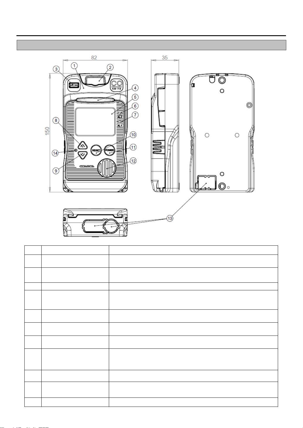
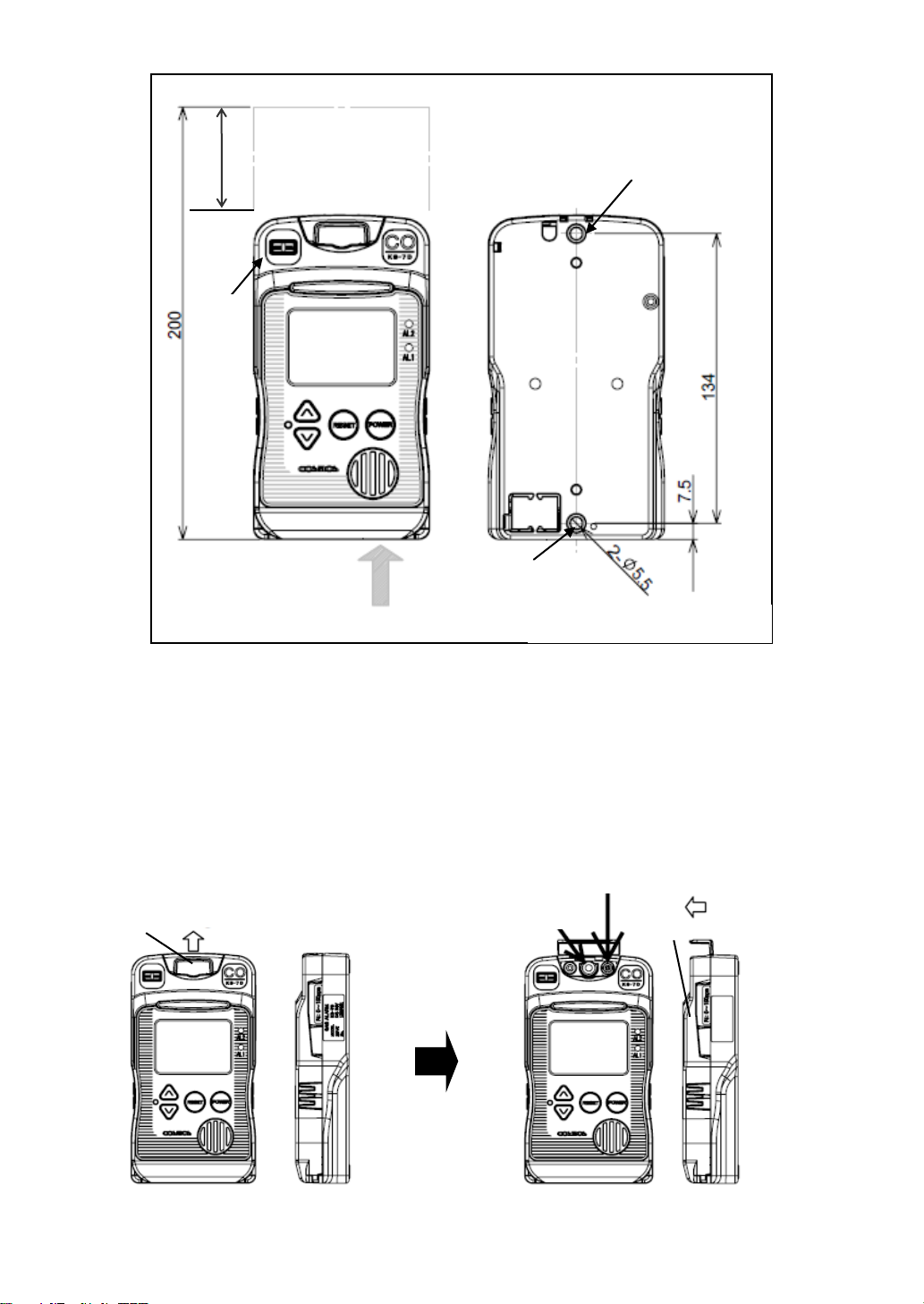
4. Unit Dimensions and Components............................................................................................4
4-1. Outer Appearance..............................................................................................................4
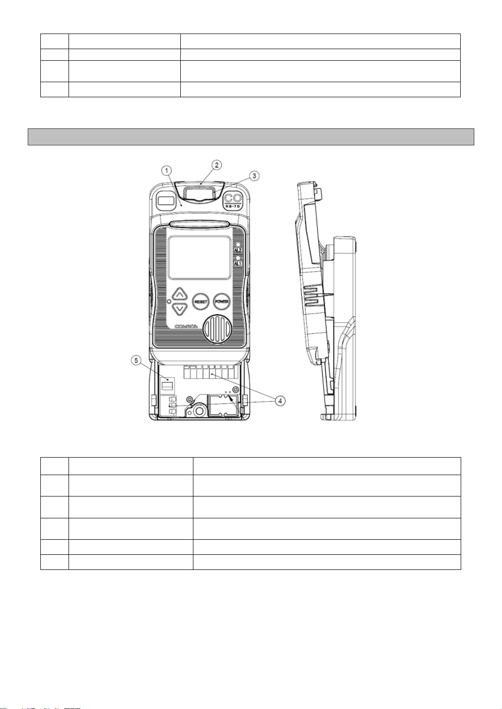
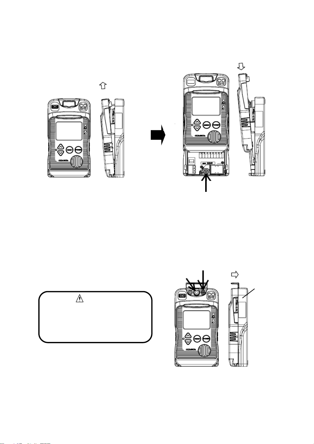
4-2. Inner Components .............................................................................................................5
5. Installation .................................................................................................................................6
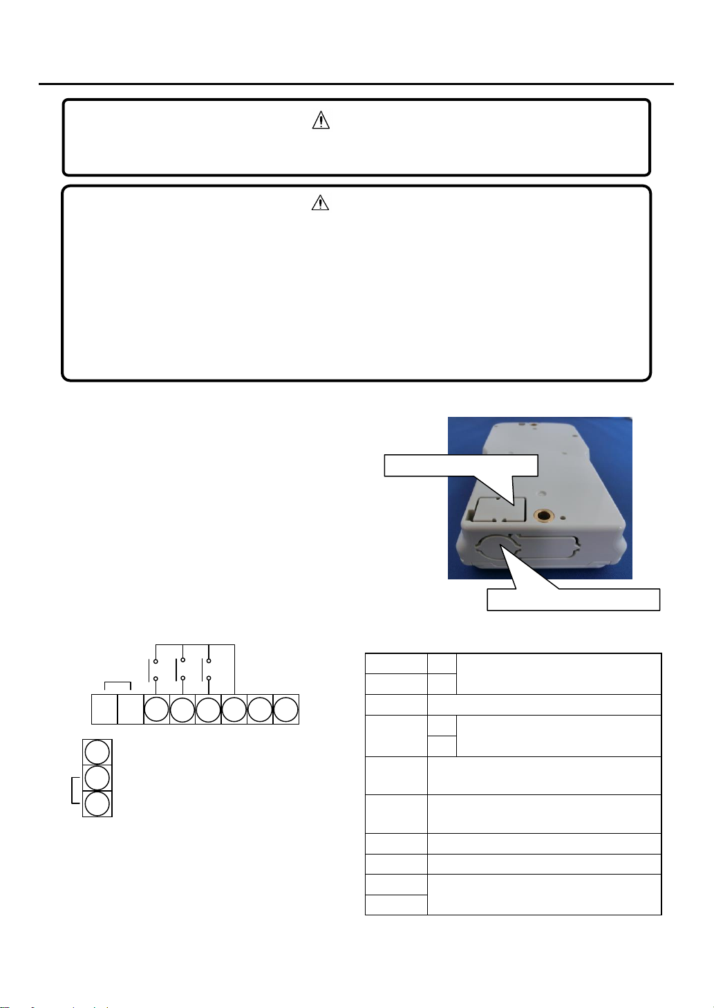
6. Wiring ........................................................................................................................................9
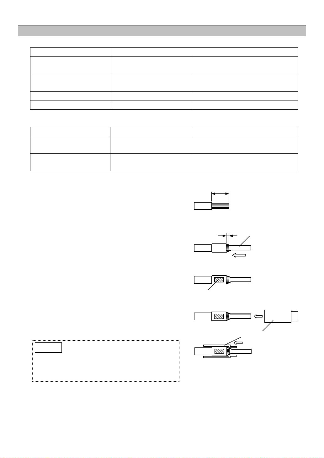
6-1. Pin Terminal/Insulated Sleeve Installation.......................................................................10
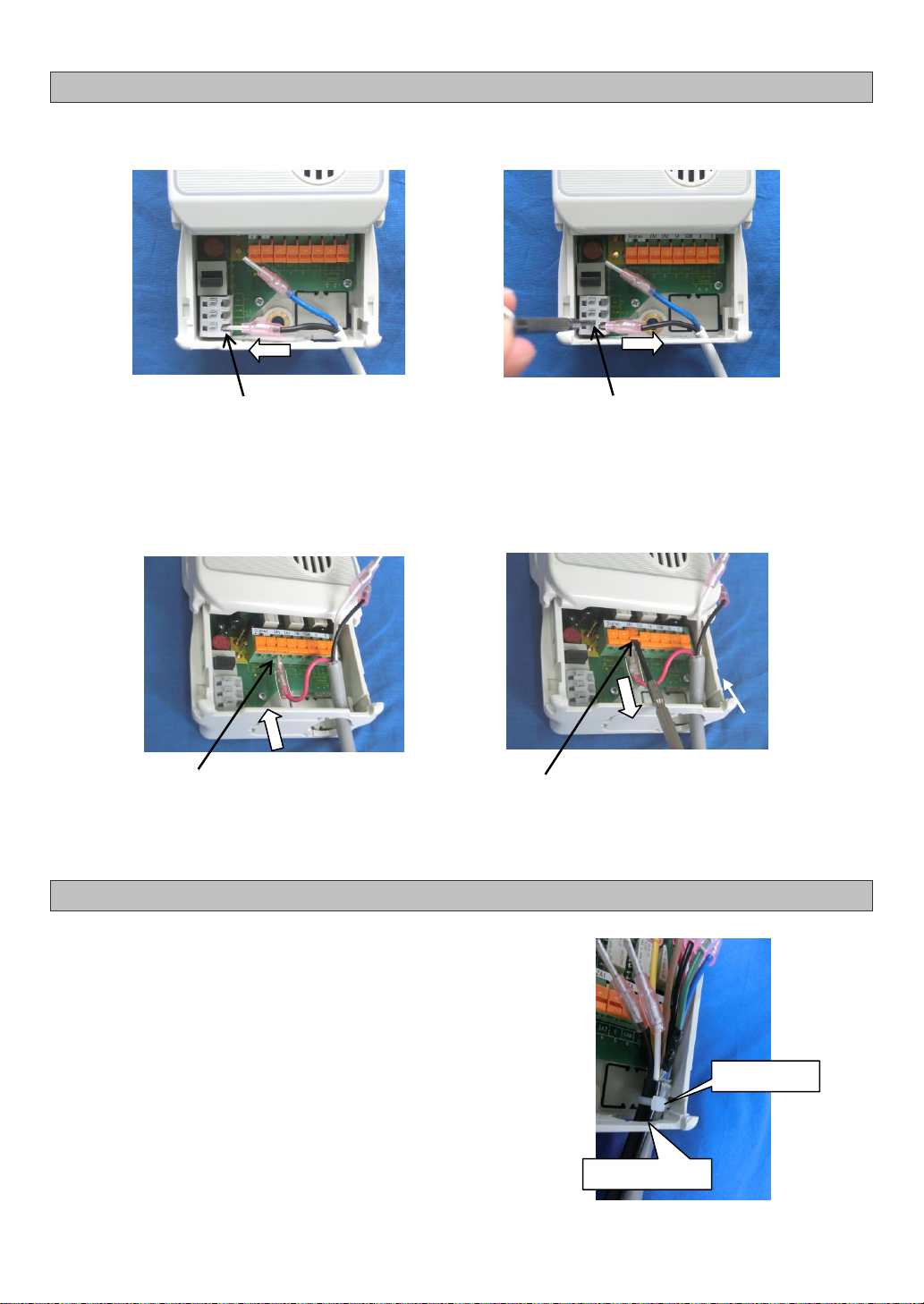
6-2. Wire Connection/Disconnection to/from Terminal Block..................................................11
6-2-1. Power Terminal Block ...............................................................................................11
6-2-2. External Output Terminal Block.................................................................................11
6-3. Cable Tie Installation .......................................................................................................11
7. Operation.................................................................................................................................12
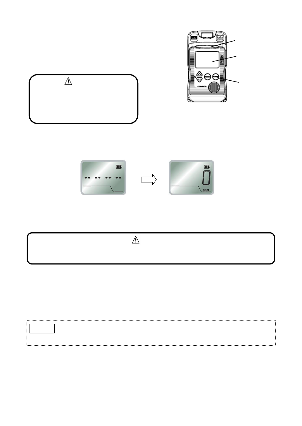
7-1. Precautions before Use...................................................................................................12
7-2. Operating Procedure .......................................................................................................12
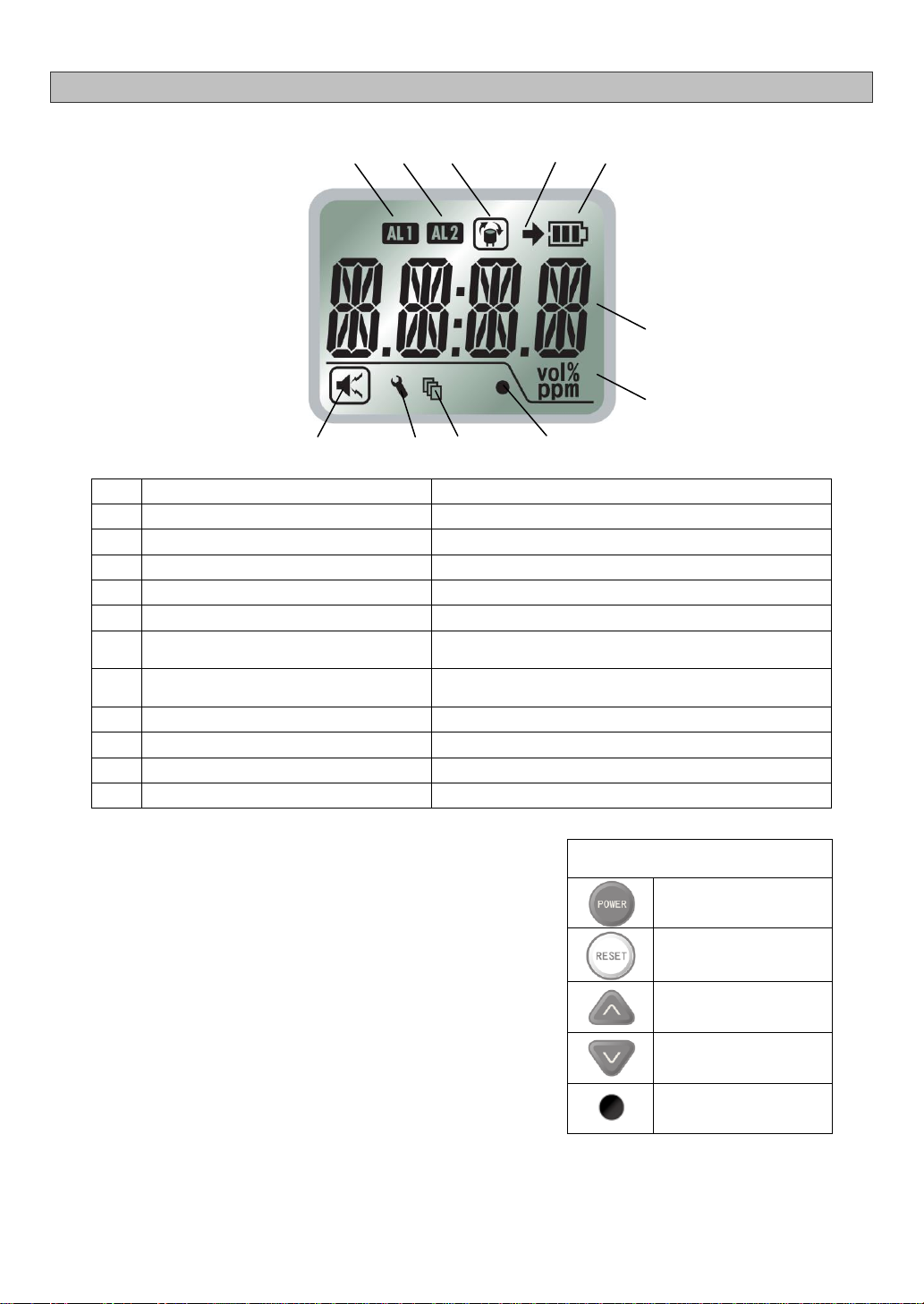
7-3. LCD Operation.................................................................................................................14
7-3-1. LCD...........................................................................................................................14
7-3-2. Normal Operation Status...........................................................................................14
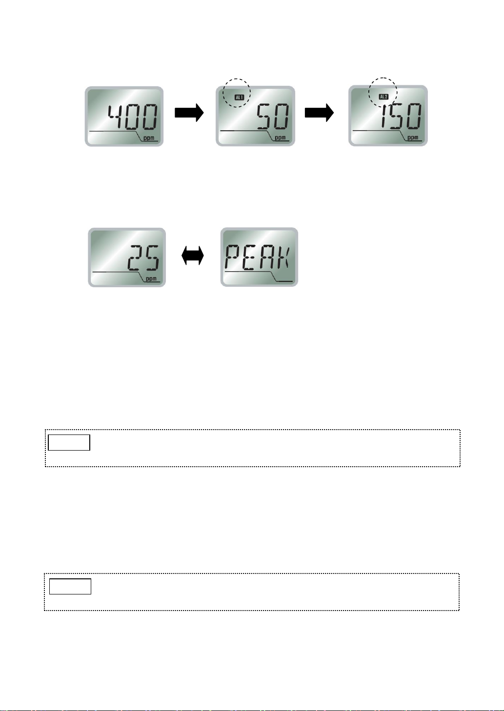
7-3-3. Full Scale and Alarm Set Values Display..................................................................15
7-3-4. Peak Value Display and Reset..................................................................................15
7-3-5. Operation during Gas Alarm .....................................................................................15
7-4. User Mode .......................................................................................................................16
7-4-1. User Mode Operation................................................................................................16
7-4-2. Switching Maintenance Mode On/Off [Mode1] .........................................................17
7-4-3. Zero Adjustment [Mode 2].........................................................................................18
7-4-4. Span Adjustment [Mode 3]........................................................................................18
7-4-5. Alarm Test [Mode 4] ..................................................................................................19
7-4-6. Alarm History [Mode 5]..............................................................................................20
7-4-7. Clock Setting [Mode 6]..............................................................................................21
7-5. Maker Mode.....................................................................................................................22
7-5-1. Maker Mode Activation..............................................................................................22
7-5-2. Operating Time Refresh............................................................................................22
7-5-3. Alarm Set Value Change...........................................................................................24
8. Maintenance............................................................................................................................25
8-1. Inspection Contents and Frequency................................................................................25
8-2. Backup/Clock Battery Replacement................................................................................27
9. Troubleshooting.......................................................................................................................29
10. Specifications.........................................................................................................................31
11. Warranty ................................................................................................................................32
12. Expected Sensor Life ............................................................................................................32
13. Detection Principle ................................................................................................................33
14. Glossary ................................................................................................................................34
15. Proper Product Disposal At End of Life.................................................................................35

- 1 -
1. Introduction
Thank you for purchasing the New Cosmos KS-7D carbon monoxide detector.
To ensure safe and reliable operation, please read this instruction manual prior to use.
This unit detects the toxic and combustible gas, carbon monoxide. The unit is intended for use in a
non-hazardous indoor area, e.g. office, laboratory, and clean room, for the early detection of a gas
leak and relaying the gas concentration value as an analog signal (4-20mADC) to external
equipment while simultaneously displaying the gas concentration value on its display.
If the gas concentration reaches a preset level, the unit will produce audio-visual alarms and activate
relay contacts, thus helping prevent serious incidents such as gas poisoning.
This manual uses Danger, Warning, Caution and Note symbols to draw attention to
procedures, materials, methods, and processes, which require particular attention.
: Indicates an imminently hazardous situation that can result in
death or serious injury.
: Indicates a potentially hazardous situation that may result in death
or serious injury.
: Indicates a hazardous situation that may result in minor injury or
property damage.
: Provides information on product handling.
DANGER
CAUTION
WARNING
NOTE

- 2 -
2. General Precautions
Carefully read this manual prior to use.
Follow the precautions below to ensure safe operation.
Only use this product in accordance with applicable laws and regulations.
Only a qualified electrician with knowledge of wiring and installation procedures should perform
wiring and installation.
▪In the event of a gas alarm, follow the safety procedures in accordance with your
company's regulations.
▪This product is not explosion-proof equipment and should not be installed in a
hazardous area.
▪Secure the cover by tightening the two fastening screws. Proper gas detection is not
possible if the cover is not tightly closed.
WARNING
▪Do not disassemble, modify, or alter the structure of this unit or its electrical circuits.
Doing so may compromise the performance of the product.
▪This product is not drip-proof equipment, and should be kept away from splashing water
▪Use the correct orientation as specified in 5. “Installation” when installing the unit to
ensure its proper performance.
▪Because of its sensor structure, the detector should not be stored in an orientation other
than instructed on the package box. If incorrectly stored, sensor output may temporarily
drop when powered even if installed in the correct orientation. The output drop may be
seen within one week after installation and usually lasts for one hour before returning to
normal. If incorrectly stored for an extended period, the output drop may last two hours.
▪The product’s analog output resolution ranges from 250 to 400 (contingent on full scale
setting). Because of the difference in resolution or number of displayed gas
concentration digits, or connected impedance, some errors in displayed gas
concentration value may be observed.
If the fault threshold needs to be set via analog output, set it to 1.0mA.
CAUTION
Operation during power outage
In the event of a power outage during operation, the detector will cease operating if
the backup battery level is insufficient. The detector will automatically resume
operation once power is restored, as long as the main power switch, under the
cover, is in the on (up) position.
A backup battery is included when delivered. Install it into the detector if the
detector needs to continue running during a power outage. The backup battery
needs to be replaced when drained, to prevent battery leakage. Remove the
backup battery from the detector before a planned power outage etc., if the battery
is expected to left depleted and not to be replaced for an extended period of time.
Refer to 8-2. “Backup/Clock Battery Replacement”for battery installation/removal/
replacement. With or without a backup battery installed, the detector’s operation
will not be affected.
NOTE

- 3 -
3. Package Contents
The following items are included in a standard package. If any items are missing or damaged,
please contact New Cosmos or its authorized representative for replacement.
Item
Qty
Description
CO detector (KS-7D)
1
Mounting screw
2
M5x12 with spring washer (Wall mounting)
Cable tie
1
Used to bundle electric cables
Pin terminal
9
Crimped to cables and inserted into the terminal block
Insulating sleeve
9
To be installed in a crimped pin terminal to provide
insulation
Instruction manual
1
This manual
Inspection certificate
1
Backup battery
1
CR2 lithium battery

- 4 -
4. Unit Dimensions and Components
4-1. Outer Appearance
Item
Component
Description/Function
1
Cover
Slide up and lift the cover to access to the main power switch and to
wire external cables. This cover is normally closed.
2
Screw cover
Houses one mounting screw, and two fastening screws that attach the
cover to the unit. This cover is normally closed.
3
Gas detection port
Gas inlet to the CO sensor.
4
Status indicator
During normal operation all three green internal LEDs are lit. In the
event of an 1st/2nd stage alarm, four internal orange/red LEDs light
sequentially.
5
LCD
Displays CO concentration, parameter values, error codes, and status
icons.
6
AL2 alarm light, red
Flashes red in the event of a 2nd stage alarm. The light will become
solid if reset by pressing the RESET button.
7
AL1 alarm light, orange
Flashes orange in the event of a 1st stage alarm. The light will become
solid if reset by pressing the RESET button.
8
▲ (Up) button
During normal operation, press to display the highest peak value of
gas concentration after powering-up on the LCD.
Used for making settings in combination with other button operation.
9
▼ (Down) button
Used for making settings in combination with other button operation.
10
RESET button
During normal operation, press to display the full scale and alarm set
values. Used for muting an on-going audio alarm.
11
POWER button
Press and hold for 3 seconds to turn on/off the detector.
Dimensions are in mm.

- 5 -
Item
Component
Description/Function
12
Speaker opening
Opening for audio.
13
Cable entry (3 places)
Make a cutout (cable entry) with a nipper to connect external cables to
the terminals.
14
Maintenance button
Recessed button used for making settings.
4-2. Inner Components
Item
Component
Description/Function
1
Cover
Slide up and lift the cover to access to the main power switch and
to wire external cables. This cover is normally closed.
2
Screw cover
Houses one mounting screw, and two fastening screws that attach
the cover to the unit. This cover is normally closed.
3
Fastening screw (2 places)
Located under the screw cover.
Screws that attach the screw cover to the unit.
4
Terminal block
Connect to external wiring.
5
Main power switch
Turns on/off the main power.

- 6 -
5. Installation
This product is not explosion-proof equipment and should not be installed in a hazardous
area.
WARNING
▪Avoid strong mechanical shock, impact or vibration to the detector by dropping or
bumping. Failure to do so may impair the performance of the detector.
▪Do not install the detector in the following conditions.
- Outdoor
- Exposure to water spray
- Outside the following operating temperature/humidity
-5 to +40 °C (no rapid temperature change)
30 to 85% RH (no condensation)
- Presence of corrosive gas
- Exposure to impact or vibration
- Presence of high frequencies or a magnetic field.
- Exposure to electrical noise
▪Install the detector in a location that ensures easy access for maintenance.
▪Install the detector vertically with the sensor on top. Proper gas detection is not possible
if installed inverted, at an angle, or horizontally.
▪Sensor height should be 75 to 150 cm from the floor unless otherwise required by
applicable laws or regulations. Install the unit with its gas detection port free from
obstructions.
▪Secure the cover by tightening the two fastening screws. Proper gas detection is not
possible if the cover is not tightly closed.
CAUTION
▪Leave a distance of more than 30mm from each side of the detector for
removal purpose.
▪Leave a distance of more than 50mm from the top of the detector to allow the
cover to slide open.
▪Leave enough space for cable wiring below the detector.
NOTE

- 7 -
Wall-mount the detector using two M5 mounting screws (pitch: 134) according to the following
procedure.
1. Open the screw cover.
2. Loosely install the mounting screw (top).
3. Loosen the two fastening screws.
4. Slightly pull the cover forward.
1. Open the screw cover
Screw cover
2. Loosely install the
mounting screw (top)
3. Loosen the two fastening screws
Cover
4. Pull the cover forward
Clearance for
cover to slide
Cable entry
Mounting hole
50
Sensor
Mounting hole
Dimensions are in mm.

- 8 -
5. Slide the cover up (cover is open).
6. Firmly tighten the mounting screw (bottom) to secure the detector to the wall.
7. Slide the cover down (cover is closed).
8. While pressing down the cover toward the case,
9. tighten the mounting screw (top).
10. Secure the screw cover to the case with the two fastening screws.
11. Close the screw cover.
CAUTION
Secure the cover by tightening the
two fastening screws. Proper gas
detection is not possible if the cover
is not tightly closed.
5. Slide the cover up
6. Tighten the mounting
screw (bottom)
7. Slide the cover down
10. Tighten the two fastening screws
Case
9. Tighten the mounting screw
8. Press down the cover

- 9 -
6. Wiring
The knockout holes for cable entry are provided
on the back and bottom of the unit, and can be
removed using a nipper.
Use a shielded cable (with 0.5 to 1.25mm2wires)
up to 500m in length with an outside diameter of
10.5mm or less.
NO: Normally Open
NC: Normally Closed
P
+
Power supply, 24 VDC
N
-
E
Earth terminal for grounding the detector
Signal
+
Analog output, 4-20mA DC
-
ZA1
1st stage alarm relay contact
(Dry NO or NC)
ZA2
2nd stage alarm relay contact
(Dry NO or NC)
TA
Fault alarm relay contact (Dry NO or NC)
COM
Common
D
Not used
C
NO contacts
-
+
R
S
C
D
COM
Signal
E
N
P
+-
ZA2
ZA1
TA
▪Remove any power source during wiring work to prevent electric shocks.
▪After wiring is completed, close the detector’s cover to prevent electric shocks.
WARNING
▪New Cosmos is not responsible for the cost or any damage resulting from controlling
external equipment (e.g. interlock) by using the carbon monoxide concentration outputs
(e.g. analog output, alarm relay contact output) from this product.
▪Connect wires to their corresponding terminals by referring to the marking on the
terminal block.
▪Keep the connection cable away from the electrical power line.
▪When using with external devices, isolate the product’s 4-20mA analog output from
power lines of external devices in order to prevent inflow current and noise.
CAUTION
Knockout hole on the bottom
Knockout hole on the back

- 10 -
6-1. Pin Terminal/Insulated Sleeve Installation
Recommended parts/tools
Part
Model (Manufacturer)
Description
Electric cable
Shielded cable (with 0.5-1.25mm2 wires)
Outer diameter: 10.5mm or less
Pin terminal
TC1.25-16 (Nichifu)
(Included in package)
Used for 0.25- 1.65mm2twisted wire
Insulating sleeve
VC1.25 (Nichifu)
(Included in package)
Crimping tool
NH1 (Nichifu)
1.25
Terminal block (reference)
Part
Model (Manufacturer)
Description
Power terminal block
ML-1400-S1L-3P
(Sato Parts)
0.65-1.6
External output terminal block
FFKDSA1/H1-5, 08-8
(Phoenix Contact)
0.2-1.5
1. Wire stripping
Strip the wire.
Recommended stripped wire length: 5.5mm.
2. Pin terminal installation
Insert the stripped wire into a pin terminal until
1mm of stripped wire can be seen from the end
of the pin terminal’s barrel.
3. Terminal crimping
Crimp the center of the barrel.
4. Insulating sleeve installation
Attach an Insulating sleeve to the crimped pin
terminal.
5.5
1
Pin Terminal
Barrel
Insulating sleeve
Completely insert
Completely insert the pin terminal into
the insulating sleeve. Not doing so may
cause an insufficient pin length when
wired to the terminal block, which may
result in a poor connection.
NOTE

- 11 -
6-2. Wire Connection/Disconnection to/from Terminal Block
6-2-1. Power Terminal Block
6-2-2. External Output Terminal Block
6-3. Cable Tie Installation
Use a cable tie for bundling the in-coming cables through the
cable entry and secure them to the unit’s wall.
The unit has a cable tie holder inside its case near the bottom.
Pre-install a cable tie by feeding it thru the tie holder and make
a loop. To easily bundle the wiring of in-coming cables to the
terminal block, feed these cables thru this loop and secure to
the case wall.
Cable tie
Cable entry
Insert each pin terminal to its
corresponding slot on the terminal block.
(Connection)
(Disconnection)
While pressing the release button with a
precision screwdriver (recommended tip
thickness: 2.6 mm), lift the pin terminal.
(Disconnection)
(Connection)
Insert each pin terminal to its
corresponding slot on the terminal block.
While pressing the release button with a
precision screwdriver (recommended tip
thickness: 3.0 mm), lift the pin terminal.

- 12 -
7. Operation
7-1. Precautions before Use
7-2. Operating Procedure
1) Follow steps 1, 3, 4, and 5 of 5. “Installation”
and slide up and open the cover. (The cover is
not fully opened)
1. Open the screw cover.
3. Loosen the two fastening screws.
4. Slightly pull the cover forward.
5. Slide the cover up (cover is open).
2) Set the main power switch to the on (up)
position.
▪Prior to operation, confirm that the power supply is 24V DC +/-10%
WARNING
▪Before turning on the unit, check that all wiring is correct. Refer to 6. “Wiring”or delivery
specifications if provided.
▪Because of its sensor structure, the detector should not be stored in an orientation other
than instructed on the package box. If incorrectly stored, sensor output may temporarily
drop when powered even if installed in the correct orientation. The output drop may be
seen within one week after installation and usually lasts for one hour before returning to
normal. If incorrectly stored for an extended period, the output drop may last two hours.
▪When the sensor output is not stable, the external relay contact may possibly activate.
To prevent possible activation of the external relay contact after the warm-up is
completed, release the interlocks of the external devices, as needed.
▪During the warm-up, the analog signal output is fixed to 4mA and the external relay
contacts are disabled.
CAUTION
Screw cover
Cover
Partly
open
Main power
switch

- 13 -
3) Follow steps 7, 8, and 10 of 5. “Installation”,
close the cover and tighten the screws.
7. Slide the cover down (cover is closed)
8. While pressing down the cover toward the case,
10. secure the screw cover to the case with the
two fastening screws.
4) Press and hold the POWER button for 3 seconds to turn on the detector. (two beeps) The three
green LEDs inside the status indicator start flashing and “- - - -”is displayed on the LCD. The
warm-up cycle lasts 90 seconds.
5) When the warm-up cycle is completed, the three green flashing LEDs inside the status indicator
become solid, the gas concentration is displayed on the LCD, and normal operation starts.
6) Perform an alarm test. (Refer to 7-4-5. “Alarm Test”)
Confirm that an alarm activates.
7) To turn off the detector, press and hold the POWER button for 3 seconds to stop the operation,
then set the main power switch to the off (down) position.
Status indicator
LCD
POWER button
CAUTION
Secure the cover by tightening the
two fastening screws. Proper gas
detection is not possible if the cover
is not tightly closed.
Once the POWER button is turned off, the backup power is not available.
Backup power is available if the main power switch is turned off, as long as the
POWER button is in the on position.
NOTE
If the indicated carbon monoxide concentration value is negative when the unit is turned on,
turn off the unit for approx. one hour to let the sensor stabilize, then turn it on again.
CAUTION
Warm-up operation
Normal operation

- 14 -
7-3. LCD Operation
7-3-1. LCD
Item
Icon/Display
Description/Function
1
Audio alarm icon
Always present.
2
AL1 icon
1st stage alarm notification.
3
AL2 icon
2nd stage alarm notification.
4
Sensor replacement icon
Sensor needs to be replaced.
5
Backup battery icon
Unit is operating on the backup battery.
6
Backup battery level indicator
Battery level of the backup battery used during power
outage.
7
Concentration value and information
CO concentration value, parameter values, error
codes, etc.
8
Unit of measurement
A unit of gas concentration.
9
Clock battery level indicator
Clock battery level is low.
10
Alarm history icon
Alarm history is being accessed.
11
Maintenance mode icon
Maintenance mode is active.
7-3-2. Normal Operation Status
During normal operation the green status indicator is fully lit,
the gas concentration value is displayed on the LCD, and
the AL1 and AL2 alarm lights are off.
Buttons and switch
POWER button
RESET button
▲(UP) button
▼(DOWN) button
Maintenance button
1
2
3
4
5
6
7
8
9
10
11

- 15 -
7-3-3. Full Scale and Alarm Set Values Display
▪Press the RESET button (one beep) to display the “full scale concentration”, “1st stage alarm set
value”, and “2nd stage alarm set value”in sequence.
7-3-4. Peak Value Display and Reset
▪Press the ▲button. (one beep) The “peak value after powering-up”and “PEAK”will be displayed
alternately.
▪To return to the normal gas concentration display, press the RESET button. (one beep)
The display will show the full scale value and alarm set value, then return to the normal gas
concentration display.
▪To reset the peak value, press the ▲/▼ button at the same time. (two beeps)
The peak value is reset then the display returns to the normal gas concentration display.
7-3-5. Operation during Gas Alarm
▪When the CO concentration reaches the alarm set value, the alarm light flashes, the status
indicator sequentially-flashes and an audio alarm sounds.
▪There are two options to clear a gas alarm, manual-resetting and self-resetting. By default, the
detector is set to manual-resetting mode. Please specify the alarm clearance option at the time of
order.
▪The alarm hysteresis range is 2ppm. The alarm will not be cleared until the gas concentration
exceeds the alarm set value by more than the hysteresis value. E.g. when the alarm set value is
50ppm and an alarm is activated, the alarm will not be cleared until the concentration reaches
47ppm or lower.
Alarm relay contact reset: If the RESET button is pressed while the
concentration is below the alarm set value, the alarm relay contact will return to
its normal position and the alarm light will turn off.
NOTE
Audio alarm mute: If the RESET button is pressed during a gas alarm, the audio
alarm will be muted and the flashing alarm light(s) will become solid. If the
RESET button is pressed and held, the alarm will not be muted.
NOTE
Full scale: 400ppm
1st stage alarm set value: 50ppm
2nd stage alarm set value: 150ppm
(Ex. Peak value is 25ppm)

- 16 -
7-4. User Mode
7-4-1. User Mode Operation
▪To enter the User mode, press the maintenance button
while the unit is on. After one beep, “1”and its
abbreviated mode name “MT”will be alternately
displayed.
▪To select the mode options, use the ▲and ▼buttons.
▪To confirm your selection, press the maintenance button. To return to the previous step, press the
RESET button.
▪To execute the selected mode, press and hold the maintenance button for 3 seconds.
▪To return to the normal operation mode, press and hold the RESET button for 5 seconds.
Mode
Mode name
Abbreviated mode name
1
Switching maintenance mode on/off
MT
2
Zero adjustment
0 ppm
3
Span adjustment
*** ppm
4
Alarm test
AL T
5
Alarm history
AL H
6
Clock setting
DATE
< 1st stage alarm >
▪Orange AL1 alarm light flashes and the status indicator sequentially-flashes orange.
▪Audio alarm beep: Fast, high and low beep tones.
▪ZA1 alarm relay contact is closed.
< 2nd stage alarm >
▪Red AL2 and A1 alarm lights flash and the status indicator sequentially-flashes red.
▪Audio alarm beep pattern: Very fast high and low beep tones.
▪ZA2 alarm relay contact closes and ZA1 alarm remains closed.
▪
▪During the User mode, gas detection, alarm operation, analog output, and
contact output activation are active as during normal operation mode.
However, audio alarm mute and alarm clearance are not active and cannot be
used.
▪Return to normal operation mode after using the User mode.
NOTE
Use a rounded pin (e.g. precision screwdriver) for pressing the maintenance
button.
NOTE

- 17 -
If the unit is returned to normal operation mode
while in the Maintenance mode, the
“concentration value”and “- - - -”will be
alternately displayed and the maintenance icon
will remain displayed.
7-4-2. Switching Maintenance Mode On/Off [Mode1]
1) Enter the User mode. Press the ▲/▼button to
select “1”. (each press of the button is followed by
one beep) “MT”and “1”will be alternately
displayed.
2) Press the maintenance button. (one beep)
“OFF”will flash.
3) Press the ▲button. (one beep)
“ON”will flash.
4) Press and hold the maintenance button for 3
seconds (beep pattern: short–long–short–short) to
confirm the selection.
The maintenance icon is displayed, and “1”and
“MT”will be alternately displayed, indicating that
the unit is in the Maintenance mode.
5) To leave the Maintenance mode, take the steps 1)
to 4) above to switch the mode from “ON”to "OFF".
Confirm the maintenance icon has turned off.
During the Maintenance mode, the external relay contacts and audio alarm are disabled.
Turn off the Maintenance mode during normal operation.
WARNING
Maintenance icon
NOTE

- 18 -
7-4-3. Zero Adjustment [Mode 2]
1) Enter the User mode. Press the ▲/▼button to
select “2”. (each press of the button is followed by
one beep) “0ppm”and “2”will be alternately
displayed
2) Press the maintenance button. (one beep)
The current CO concentration (ppm) will be
displayed.
3) Check that there is no gas present. Press and
hold the maintenance button for 3 seconds to start
a zero adjustment. (beep pattern:
short-long-short-short)
“0ppm”and “2”will be alternately displayed,
indicating that the zero adjustment is complete.
7-4-4. Span Adjustment [Mode 3]
1) Press the ▲/▼button to select “3”. (each
press of the button is followed by one beep)
“*** ppm”(span adjustment concentration)
and “3”will be alternately displayed.
▪Perform a zero adjustment in clean air that is free from target gas or interfering gases.
▪Proper gas detection is not possible without a correct zero adjustment
CAUTION
▪Mode 3 (span adjustment mode) is for manufacturer use only. For span adjustment,
contact your New Cosmos representative (fees apply). Proper gas detection is not
possible without a correct span adjustment.
CAUTION
(Ex.Current concentration
is 3ppm)
(Ex. Span adjustment concentration is 400ppm)
Other manuals for KS-7D
1
Table of contents
Other New Cosmos Electric Gas Detector manuals

New Cosmos Electric
New Cosmos Electric NV-100C User manual

New Cosmos Electric
New Cosmos Electric KD-12B User manual

New Cosmos Electric
New Cosmos Electric XP-302M-R-A-1 User manual

New Cosmos Electric
New Cosmos Electric XA-4400II User manual

New Cosmos Electric
New Cosmos Electric XPS-7II User manual

New Cosmos Electric
New Cosmos Electric PS-7-M User manual

New Cosmos Electric
New Cosmos Electric PS-7-M Use and care manual

New Cosmos Electric
New Cosmos Electric KD-12 User manual

New Cosmos Electric
New Cosmos Electric XP-3000II Series User manual

New Cosmos Electric
New Cosmos Electric NV-100H User manual