Polon-Alfa DUR-40Ex Manual

DUR-40Ex
Intrinsically Safe
SMOKE DETECTOR
Installation and Maintenance Manual
IK-E317-001GB
IB Issue

2 IK-E317-001GB
The Universal Optical moke Detector DUR-40Ex covered by the present manual, complies with the
requirements of the following European Union Directives:
CPD 89/106/EWG on construction materials;
EMC 2004/108/WE on electromagnetic compatibility;
ATEX 94/9/WE on equipment and protective systems intended for use in potentially
explosive atmospheres.
The DUR-40Ex moke Detector has been approved with the EC-Certificate of Conformity No.
1438/CPD/0033 issued by the Fire Protection cience and Research Centre (CNBOP) Józefów, Poland,
a EU notified authority No. 1438, confirming its compliance with the requirements of PN-EN 54-
7:2004 standard.
The Central Mining Institute, Katowice, Poland, a EU notified authority No. 1453, has issued the
following certificates concerning the DUR-40Ex moke Detector:
- WE type Inspection Certificate No. KDB 05ATEX190X + upplement No. 1
- Quality Assurance Acknowledgement No. GIG 04 ATEXQ 021
- WE Conformity Declaration No. 3/E317/2010.
The Certificates may be downloaded from www.polon-alfa.pl web site.
1438; 1453
Polon
-
Alfa Limited Partnership
155, Glinki treet, PL 85-861 Bydgoszcz, POLAND
06
1438/CPD/0033
EN 54
-
7
DUR-40Ex Optical S oke Detector (scattered light principal based,
conventional, universal, detachable)
Application – fire safety
Technical data
-
IK
-
E317
-
002
GB
manual
Read the manual carefully before assembling and operation of the base and the base attachment.
Any nonconformity with the instructions contained in the manual may be harmful or may cause
violation of the law in force
POLON-ALFA bears no responsibility for any damage resulting from usage inconsistent with the
manual.
The waste product shall be passed to a waste electric and electronic
equipment collection point.
NOTE: The manufacturer reserves the right to change specifications of products at any time
without prior notice.

IK-E317-001GB 3
1 PURPOSE
The DUR-40Ex Universal moke Detector is designed for detection of smoke that accompanies the
majority of fires. It enables fire detection at its initial stage when material starts to smoulder what
happens a long time prior to the appearance of open flame and a noticeable temperature rise. It
detects every test fire that is typical for optical detectors and additionally TF1 test fire typical for
ionisation smoke detectors. The DUR-40 smoke detectors are connected to fire detecting lines
through intrinsically safe barrier or separator of the following para eters: Uo ≤ 25 V, Io ≤ 99 A.
The detectors are installed in rooms and zones qualified as 1st and 2nd explosive hazard category
resulting from potential explosion danger of explosive gases or inflammable liquid vapours that are
ranked at IIA, IIB and IIC explosiveness subgroups and T1 up to T6 temperature classes. The detector
is characterised by an increased resistance to wind influence and atmospheric pressure changes. It
provides a high level of visible and nonvisible smoke sensitivity.
2 TECHNICAL SPECIFICATIONS
Operating voltage 12 V ÷28 V
Maximum monitoring mode current ≤ 60 µA
Alarm current 20 mA
Detector sensitivity 0.2 dB/m
Maximum mounting height *) 11 m *)
Maximum supervised area *) 60 ÷ 80 m
2
*)
Operating temperature range from - 25 °C to + 55 °C
Relative humidity up to 95 % at 40 °C
Dimensions (without base) Ø 115 x 43 mm
Mass (without base) 0.15 kg
Casing colour black
Casing ingress protection IP 42
Intrinsic safety rating Ex i
b
IIC T6
*) design guidelines must be observed
3 INSINTRIC SAFETY PARAMETERS
Supply line arginal para eters:
Maximum input voltage U
I
25 V
Maximum input current I
I
99 mA
Maximum input power P
I
0.613 W
Maximum inner capacity C
I
0*
Maximum inner inductance L
I
0*
Maximum outer capacity C
o
110 nF **
Maximum outer inductance L
O
2.5 mH**
Detector-alar indicator connecting line para eters:
Maximum output voltage U
O
25 V***

4 IK-E317-001GB
Maximum output current I
O
99 mA***
Maximum output power P
O
0.613 W***
* negligible parameters
** represents the sum of capacity and inductance resulting from the length of cables that may be connected
to the detector
*** values that may occur in case of uncountable damages.
Intrinsically safe barrier or separator para eters:
Maximum output voltage U
O
25 V
Maximum output current I
O
99 mA
Maximum output power P
O
0.913 W
Maximum outer capacity C
O
110 nF
Maximum inner inductance L
O
2.5 mH
Connecting cable exa ple (YnTKSY):
Core diameter mm 0.8 1.0
ingle core resistance Ω/km 37.5 24
Pair of cores capacity nF/Km 120 120
Inductance mH/km 0.7 0.7
4 SAFETY CONDITIONS
4.1 Repairs and aintenance
Any maintenance works or periodic inspection shall be executed by skilled personnel employed by
companies authorised and trained by POLON-ALFA.
Any repairs must be carried out by the manufacturer. POLON-ALFA bears no responsibility for the
operation of any apparatus being repaired by unauthorised personnel.
4.2 Works at height
Any detector installation works carried out at height must be executed with particular care utilising
tools and machinery in good working condition.
pecial attention shall be given to stability of ladders, elevators, lifts, etc.
Any electric tool shall be used strictly obeying the safety rules stated in instruction manuals by
manufacturers.
4.3 Anti-dusting eye protection
It is obligatory to use protective anti-dusting glasses and masks during detector installation works
that produce high amount of dust, such as hole drilling in ceilings.
5 INTEROPERATION WITH CONTROL PANELS
The DUR-40Ex detectors are provided for working together in fire detecting lines with control panels
manufactured by POLON-ALFA or by other producers that obtained POLON-ALFA’s consent and
compatibility declaration.
The DUR-40Ex detectors should be applied in explosion hazard zones being connected to detecting
lines behind an intrinsically safe barrier or separator indicated in the control panel technical
documentation.

IK-E317-001GB 5
6 CONSTRUCTION DESCRIPTIONS
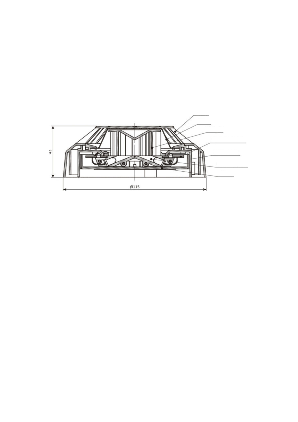
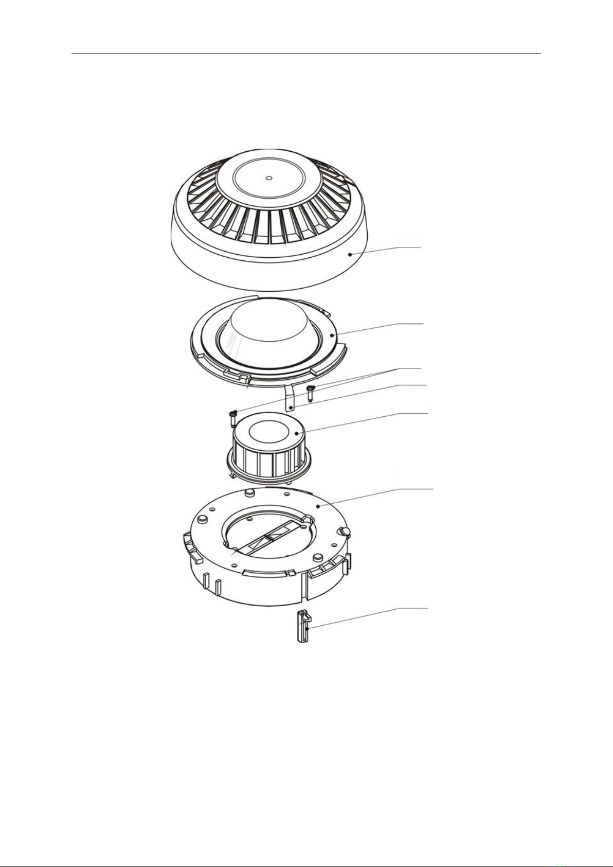
The detector’s mechanical construction is shown on Figure 1. Its basic element is a detecting optical
module consisting of transmitting and receiving diodes. They are fixed in a holder in such a way that
radiation emitted by the transmitting diode does not reach the receiving diode directly. The
detecting module (holder with diodes) is mounted on a printed board that comprise also a circuit
with the detector’s monitoring processor. The optical module is protected by a labyrinth, damping
external radiation. A wire mesh net prevents irruption of small insects or bigger pieces of dirt. The
whole structure is placed in a black plastic housing consisting of basket, screen and detector casing.
The DUR-40Ex detector is installed in the G-40 base where also detecting line cables are connected
to.
creen
Detecting module
Detector casing
Printed board
M esh
Basket
Laby rinth
Fig.1 DUR-40Ex mechanical structure
7 PRINCIPLES OF OPERATION
The DUR-40Ex is a Tyndall effect optical smoke detector – light scattering on smoke particles. Its
basic element is a detecting optical module consisting of an electroluminescence diode that
transmits radiation and an optical receiving diode. The optical module and surrounding measuring
chamber are protected by a labyrinth which is shaped to dump both external light and radiation
resulting from internal reflexes of the transmitting diode light. When smoke particles enter the
measuring chamber, they reflect the light emitted by the transmitting diode. The reflected light
reaches the optical diode producing photocurrent which is first strengthened and processed and
then analysed by the microprocessor installed inside.
An alarm mode is indicated with red light emitted by a signalling diode installed on the detector
casing. The indicator enables fast localisation of the activated detector and is helpful in periodic
detector’s inspections. In case the detector is installed in a hard to reach space, an additional optical
alarm signal can be obtained by connecting the WZ-31 alarm in an accessible and visible place.
The DUR-40Ex detector has a built-in self-regulation digital system maintaining constant sensitivity to
progressing dirt build-up inside the measuring chamber. After exceeding the pre-set regulation
threshold the detector sends an alarm signal to the control panel.
8 MAINTENANCE INSTRUCTIONS
The DUR-40Ex optical smoke detector should undergo periodic inspections, carried out at least once
in 6 months, to prove that the detector operates correctly and works together with the fire control
panel properly. Those checks are executed using smoke imitating aerosol.
The detector’s long-term utilisation may result in dirt built-up inside its measuring chamber.

6 IK-E317-001GB
After exceeding the set self-regulation threshold resulting from progressing dirt build-up in optic
chamber, the detector may enter an alarm mode. It is why prior cleaning of detector’s optical
module (labyrinth and lenses of both transmitting diode and receiving photodiode) is vital.
Basket
Basket
Mesh
crew
Clinch
Labyrinth
Casing with
printed board
Blockade
Fig. 2 Detector elements
The detector assembly and dismantling process is shown on Figure 2. In order to dismantle a
detector the following operations should be carried out:
- pressing the long mesh clinch turn the casing right against the basket until it is released
- remove the screen
- unscrew two labyrinth fixing screws and remove the labyrinth
- carry out necessary cleaning.

IK-E317-001GB 7
It is recommended to clean the detector using a delicate brush and vacuum-cleaner; it is also
allowable to use compressed air. The labyrinth may be washed with warm water mixed with wash-up
liquid. No water stain should be left on the labyrinth surface after washing and drying.
After cleaning the detector should be assembled, tested using a smoke imitator and installed again in
the detecting line. In order to assemble the detector:
a) fix the labyrinth with two screws
b) install the screen
c) place the basket in the opposite direction as it is shown on the drawing
d) insert the shield into the basket so that the diode is placed slightly to the right against the
glass
e) turn the detector casing maximally to the left.
Note:
In case the cleaning does not produce the required result, it is necessary to send the detector to the
manufacturer for repair.
9 DETECTOR INSTALLATION
The DUR-40Ex detectors shall be installed (location, height, etc.) in accordance with general design
rules. They are mounted in places where the equipment working or materials stored may emit smoke
resulting from their burning or smouldering. The detectors are installed in 40 model range bases.
The detection line installation instructions are shown on Figure 3 and in the G-40 Installation and
Maintenance Manual. It is possible to connect the WZ-31 alarm indicator that provides additional
visual alarm of a particular detector or a group of detectors.
Alarm installation cables should be placed in accordance with low-voltage (below 42V) circuit
regulations.
Line input/output Line output/input
Fig. 3. Clamps of a base interoperating with detector plug
Note:
The detectors cannot be installed in corrosive atmosphere containing caustic gases and vapours or
dust pollution. team condensation on the detector surface is strictly forbidden.

8 IK-E317-001GB
10 STORAGE AND TRANSPORTATION
10.1 Storage
The DUR-40Ex detectors must be kept in closed rooms free of any caustic gases and vapours at
ambient temperature between 0 °C and +40 °C and relative humidity not exceeding 80% at + 35
o
C.
The detectors shall not be exposed to direct sunlight or high temperature emitted by heaters.
The storage period of the detector in transport package should not exceed 6 months.
10.2 Transportation
The DUR-40Ex detectors should be carried in closed spaces of transport means in proper packages
that meet appropriate transport regulations. Transport temperature shall not be lower than - 40 °C
and higher than + 70 °C; relative humidity shall not exceed 95% at + 45 °C or 80 % at + 70 °C.
IK-E317-002GB/07.2009/05.2012
Table of contents
Other Polon-Alfa Smoke Alarm manuals

Polon-Alfa
Polon-Alfa POLON 4000 DOP-6001 Manual

Polon-Alfa
Polon-Alfa DUR‐4046 Manual

Polon-Alfa
Polon-Alfa ADR-20N Manual

Polon-Alfa
Polon-Alfa DOP-6001R Manual

Polon-Alfa
Polon-Alfa DOR-4046 Manual

Polon-Alfa
Polon-Alfa DOR-4043 Manual

Polon-Alfa
Polon-Alfa POLON 4000 Series Installation guide

Polon-Alfa
Polon-Alfa DOT?4046 Manual
Popular Smoke Alarm manuals by other brands

B.E.G.
B.E.G. SMARTHOME SD1-N Installation and operating instructions

SONA Electronics
SONA Electronics SM-SN-1 Installation and user guide

Inovonics
Inovonics EE1265 Installation and operation manual

First Alert
First Alert P1210 user manual

First Alert
First Alert PC910 user manual

Vega Absolute
Vega Absolute SMART-SS0102 user manual