Polon-Alfa DOP-6001R Manual

OPTICAL BEAM
SMOKE DETECTOR
DOP-6001R
_________________________________________________________________________________
INSTALLATION
AND MAINTENANCE MANUAL
IK-E343-002GB
Edition III

The DOP-6001R beam smoke detector, covered by this manual, complies with the requirements of the
following European Union directives:
CPRRegulation (EU) No. 305/2011 of the European Parliament and of the Council of 9 March 2011
laying down harmonised conditions for the marketing of construction products and repealing
Council Directive 89/106/EWG;
EMC The electromagnetic compatibility (EMC) Directive 2014/30/EU
LVD 2014/35/EU - on low-voltage supply electric equipment.
The BRE Global ltd, Notified Body has been issued for the product the LPCB certificate no. 1283a confirming
the possession of technical features/parameters required by EN 54-12:2002
The features/technical parameters above that exceed the requirements of the aforementioned standards
and other features/parameters specified in this manual that are not specified in the mentioned standards
are confirmed by the Manufacturer.
Declaration of Performance has been issued for DOP-6001R beam smoke detector.
The certificate and the Declaration of Performance can be downloaded from www.polon-alfa.pl
Read the manual carefully before the detector assembling and commissioning. Any nonconformity with the
instructions contained in the manual may be harmful or may cause violation of the law in force
The manufacturer, POLON-ALFA shall not bear responsibility for any harms resulted from the unit
application discordantly to the requirements of this instruction.
A waste product, unsuitable for further use, shall be passed to
a waste electric and electronic equipment collection point.
NOTE: The manufacturer reserves the right to change product specifications at any time without prior notice.

Table of contents
1. PURPOSE……………………………………………………………………………………………………………………………………………
2. TECHNICAL SPECIFICATIONS………………………………………………………………………………………………………………
3. PRINCIPLE OF OPERATION………………………………………………………………………………………………………………….
4. DESIGN……………………………………………………………………………………………………………………………………………….
5. INSTALLATION……………………………………………………………………………………………………………………………………..
6. OPERATING CONDITIONS AND MAINTENANCE……………………………………………………………………………………
7. SAFETY CONDITIONS……………………………………………………………………………………………………………………………
7.1 Repairs and maintenance
7.2 Works at height
7.3 Anti-dusting eye protection
7.4 Eye protection against laser beam operating equipment
8. STORAGE AND TRANSPORT
9. DESIGN RECOMMENDATIONS

1 PURPOSE
The DOP-6001R Beam Smoke Detector is designed for smoke detection at the start of a fire. It is especially
suitable for protection of premises where, in the first phase of the fire, smoke appearance is expected and
in which, due to a large space area, installation of a greater number of spot smoke detectors would be
necessary. Beam smoke detectors (in comparison with spot smoke detectors) are sensitive to a medium
smoke density value on a long path of the infrared radiation beam and therefore they are especially
suitable for application under high ceilings/roofs or in those places where smoke can be diffused over a
large area before detection.
Exemplary objects especially suitable for this type detector installation are: churches, cathedrals,
monumental buildings with valuable historic ceilings, theatres, sports halls, industrial shops, very high
rooms, in which spot detectors would be ineffective, and rooms with a differentiated ceiling or roof design.
A distinctive feature of the DOP-6001R detector is its arrangement of a transmitter and a receiver in one
enclosure and interaction with a prism reflector or a reflector panel placed on the opposite wall. A single
casing embraces a laser target viewfinder that enables optical path axis alignment between the detector
and the reflector/reflector panel.
The DOP-6001R beam smoke detector is intended to interoperate with any fire detection and alarm control
panel that ensures power supply in the range between 9.5 V and 28 V and current > 100 mA. Its alarm
signal is the relay non-potential contact switch over. The detector operates in closed premises at ambient
temperatures ranging from –25 oC to +55 oC and relative humidity up to 95 % at 40 oC.
2 TECHNICAL SPECIFICATIONS
Operating voltage in a detection line 9.5 V ÷ 28.0 V
Quiescent current from 9.5 to 28 V (8 ÷ 30) mA
Alarm current from 9.5 to 28 V (20 ÷100) mA
PU and PA relay contact load max. 1 A/30 V
Current at light beam interruption < 0.3 mA
Current at service signal –optics contamination < 0.3 mA
Sensitivity thresholds (to be chosen) 18 %; 30 %; 50 %
Operating distance
-with E39-R8 prismatic reflector (Fig. 6) from 5 m to 50 m
-with 4xE39-R8 reflector panel (Fig. 7) from 50 m to 100 m
Detector angular tolerance ± 0.5 °
Reflector angular tolerance ± 5 °
Power supply of laser viewfinder (during alignment) 6F22 (9 V) battery
Operating temperature range -25 °C ÷ +55 °C
Admissible ambient relative humidity up to 95 % at + 40 °C
Ingress protection IP40
Dimensions 129 mm x 80 mm x 84 mm
Mass (together with adjustment basis) 0.35 kg
Casing colour white (other on request)
Suitability in test fire detection TF1, TF2, TF3, TF4, TF5, TF7, TF8

Fig. 1 DOP-6001R detector with prism reflector
3 PRINCIPLE OF OPERATION
The DOP-6001R detector consists of an infrared (IR) light transmitter and a receiver located in a single
enclosure, and an interoperating separate E39-8R prism reflector or 4xE39-8R reflector panel. The detector
operation principle consists in continuous analysis of optical air transparency in the space between the
detector and the reflector (reflector panel).
The detector can be in one of three modes: supervision, alarm, fault (light beam interruption or caused by
contamination). If a certain, defined quantity of aerosol (smoke) is found in the air, reducing optical
transparency below a set threshold, then the detector enters the alarm mode. Complete interruption of the
radiation beam (or its reflection due to an object occurrence in its optical path) is signalled as a fault,
because even the largest smoke concentration in the air does not cause an entire interruption of the
detector optical path. When the air is clear, the detector is in the supervision mode.
Long lasting detector operation, especially in high dust level premises, may lead to contamination (dust
build-up) of optical parts of the detector and the reflector/reflector panel. In order to maintain constant
sensitivity and fire detection ability during a long time period, the detector is equipped with automatic
compensation circuits to monitor its contamination and environment impact conditions. The circuits ensure
the same sensitivity threshold in the whole compensation range. At a certain contamination level, the
detector signals the fault mode denoting a necessity to undertake servicing and cleaning works. However,
even in this mode, the detector is still able to detect smoke and trigger an alarm mode. A contamination
caused fault requires cleaning works of the reflector/reflector panel and the detector front surface. After
cleaning, the detector adjusts to new external conditions and automatically changes its mode from fault to
supervision.
The DOP-6001R detector analysis function is fulfilled by a microprocessor. After the detector optical path
adjustment and pressing the START push button, microprocessor circuits analyses the ambient temperature
and the settled sensitivity threshold. A self-adjustment program is switched on after entering these data
into the detector memory. The self-adjustment process terminates after achieving a reference value with
5 % tolerance. Afterwards, the decision criteria are drawn up for various fire phenomena runs, for
instance for fast or slow fire development. The data are kept in the detector non-volatile memory and
periodically checked. Any measured value change (against the assumed decision thresholds) caused by a
smoke, after triple verification, is treated by the microprocessor as a fire.

4 DESIGN
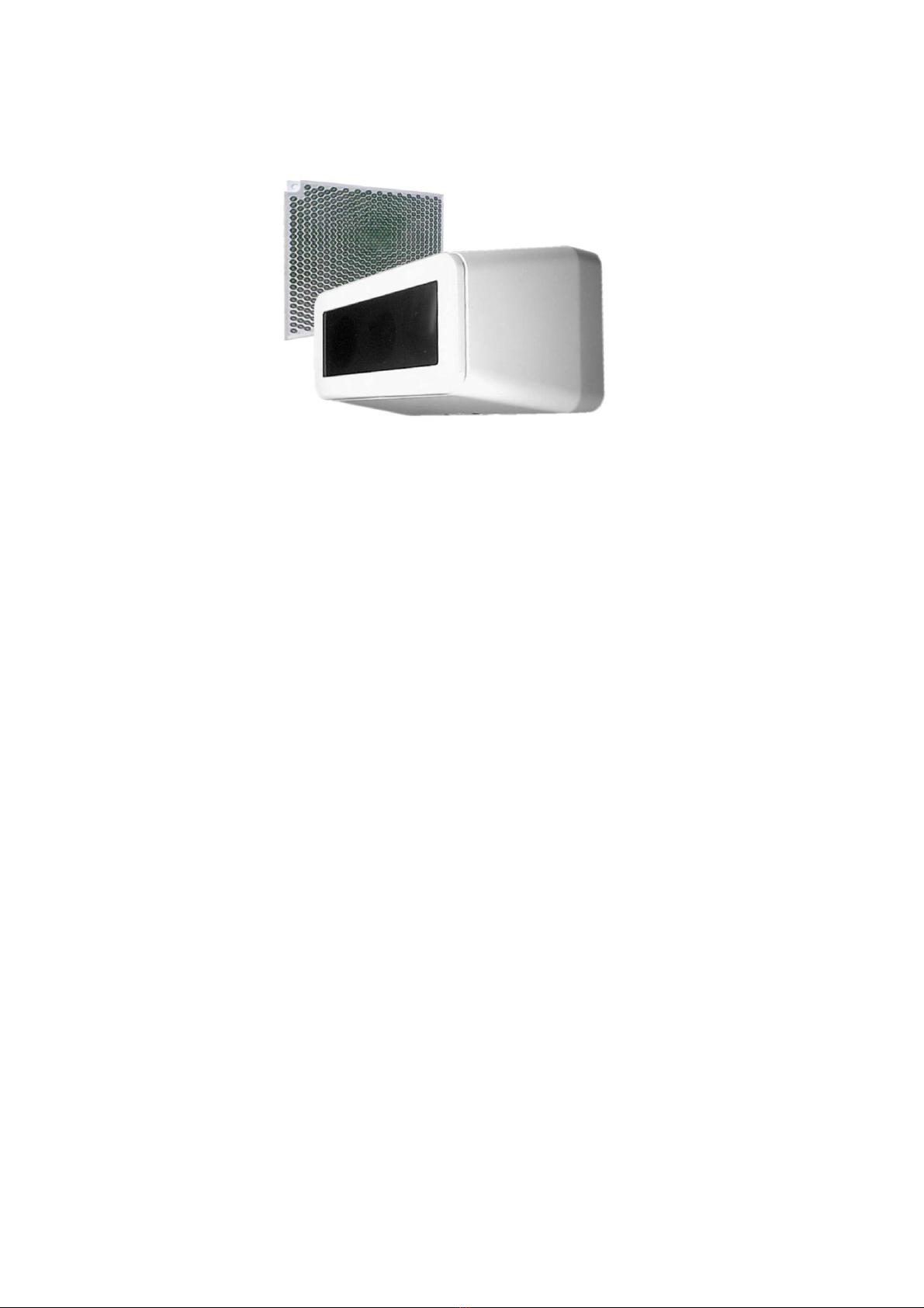
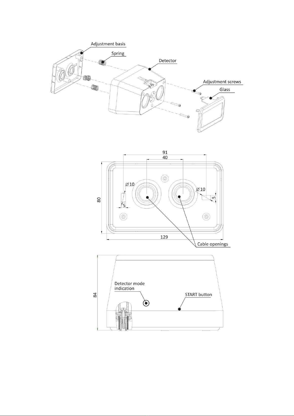
The DOP-6001R detector design is shown in Fig. 1 and Fig. 3. The detector casing, made of plastic, embraces
electronic circuits and optical elements of the transmitter and receiver as well as a laser diode that
facilitates the detector easy optical alignment. The lenses for infrared beam focusing are covered with a
detachable filter. On the detector back side a connecting block is mounted, to connect power supply wires
and four terminal blocks of the PU and PA relay contacts. The detector is fastened to the wall with a metal
adjustment basis. On the detector front part an optical fibre for illuminating diodes is placed as well as the
START push button that initiates the detector adjustment process.
The illuminating diode colour signals accordingly:
- green one –a state of the detector self-adjustment to the detector-reflector/reflector panel
distance, when the signal level is too high;
- yellow one –a state of the detector self-adjustment to the detector-reflector/reflector panel
distance, when signal level is too low;
The self-adjustment process takes approximately 30 seconds. When the detector is correctly adjusted, it
switches to the supervision mode and in case of any error, including wrong self-adjustment, the yellow LED
flashes every 2 sec.
- red one –an alarm mode;
- green diode flashing (every 10 seconds) –a supervision mode
The START push button enables initiation of the detector adjustment process (self-adjustment) and the
detector parameters renewed set-up after optical parts cleaning works.
5 INSTALLATION
The DOP-6001R detector interoperates with a reflector panel and then its operating distance ranges from
50 m to 100 m, or with the E39-R8 prism reflector at the operating distance between 5 m and 50 m. The
reflector or the reflector panel as well as the M42-00 00 00 service kit, containing test foils and an
adjustment mirror, are not included in the detector standard pack and should be ordered separately.
In case the detector is seen with difficulty or is installed in a hardly accessible place, it is possible to connect
the WZ-31 additional operation indicator to be placed in a convenient and visible place.
Before installation, it is necessary to declare an alarm mode and a sensitivity threshold. The operations are
executed using appropriate jumpers placed on the back side of the detector casing, pursuant to Fig. 6. One
of the criteria taken into consideration when choosing sensitivity may be the distance between the
detector and the reflector/reflector panel, and so:
-for a distance from 5 m to 20 m –18 % sensitivity is recommended;
-for a distance from 20 m to 50 m –30 % sensitivity is recommended;
-for a distance from 50 m to 100 m –50 % sensitivity is recommended.
It is possible to set sensitivity level experimentally: adopting it to a certain environment in the case of the
detector difficult operating conditions. The DOP-6001R detector and the reflector/reflector panel are
mounted on opposite walls, pillars or other construction elements of the premises. The walls or pillars must
be stable and vibration-free. The detector adjustment base should be mounted on a wall and the
reflector/reflector panel - on the opposite wall. The detector should be placed on the adjustment base (Fig.
3) after preliminary connection of the wires to the connecting blocks in accordance with Fig. 4. The
detector should be fixed to the basis with three screws that are accessible from the front side (after
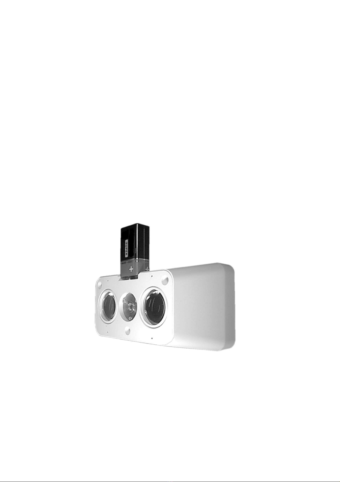
removing the cover). Then a 6F22 battery should be connected to the laser viewfinder contacts.

Before alignment, the mirror (part of the service kit) should be placed on the reflector panel and press
down, as it is shown in Fig. 9. With the help of three positioning screws, the detector laser beam should be
aimed at the centre of the reflector or the mirror from the service kit. The adjustment screws help in
precise alignment so that the laser beam returns to the detector front plate after being reflected from the
reflector. The mirror should be removed after proper regulation of the optical path between the detector
and the reflector. The prism reflector position cannot be adjusted and it is recommended to fix it to a flat
substrate with screws or glue.
The detector is properly aligned with the reflector/reflector panel when the reflected laser light illuminates
the detector. In such the situation the external battery should be disconnected, the detector cover should
be mounted and the START push button should be pressed. As a result, one of the diodes: yellow or green
shall be lit in a pulse manner (every 2 s). After ca. 40 sec. after the detector is properly aligned, the green
LED should flash every 10 seconds, what stands for a proper adjustment of the infrared beam to the
distance between the detector and the reflector/reflector panel. During this adjustment process, the
detector, being connected to a control panel, signals a fault mode. If the yellow LED flashes after
adjustment is completed and the connected control panel still signals a fault, this means that the detector
adjustment has failed.
Note:
The detectors should not be exposed to direct sunlight operation.
The detector/reflector alignment with a help of a laser beam should be carried out in a dark room.
Fig. 2 DOP-6001R detector during optical path alignment
6OPERATING CONDITIONS AND MAINTENANCE
The DOP-6001R smoke detector long-lasting operation, especially in dusty premises, may result in
contamination (dust, dirt accumulation) of the optical part of the detector and of the reflector/reflector
panel. After exceeding a program determined contamination compensation range, the detector transmits a
fault signal to the control indicating the necessity to call a maintenance technician. The detector is still able
to detect fire threat and enter an alarm mode. The contamination caused fault notification entails cleaning

of the reflector/ reflector panel and the detector front plate. After cleaning the above mentioned elements,
the START push button (located inside the detector) should be pressed in order to adjust the detector to
new external conditions. After the adjustment, the detector automatically alters its mode from a fault to a
supervision one.
It is possible to check proper operation of the DOP-6001R detectors installed in fire detecting systems
during their maintenance inspection by concealing partly the detectors optical path. It can be carried out
using a special damping plastic foil with overprints appropriate to the detector three sensitivity levels –
18%; 30%; 50% (Fig. 10). A plastic sheet with overprint consistent with the detector set sensitivity level
should be put on the detector front plate, what should trigger an alarm mode. The DOP-6001R detector
testing foil with overprints is included in the service kit.
During renovation or painting works carried out in the premises where detectors are installed, the
detector and reflector/ reflector panel should be taken out or protected. Detectors which are damaged in
the time of painting and renovation works due to a fault of persons, who execute them, are not subject
to warranty repairs.
7 SAFETY CONDITIONS
7.1 Repairs and maintenance
Any maintenance works or periodic inspection shall be executed by skilled personnel employed by
companies being authorised or trained by POLON-ALFA. Any repairs must be carried out by the
manufacturer. POLON-ALFA bears no responsibility for the operation of any apparatus being serviced and
repaired by unauthorised personnel.
7.2 Works at height
Any detector installation works carried out at height must be executed with particular care utilising tools
and machinery in good working condition. Special attention shall be given to the stability of ladders,
platforms, etc. Any electric tool shall be used strictly obeying the safety rules specified in the manufacturer
instruction manuals.
7.3 Anti-dusting eye protection
It is obligatory to use protective anti-dusting glasses and masks during detector installation works that
produce high amount of dust, such as hole drilling for detector base mounting on ceilings/walls.
7.4 Eye protection against laser beam operating equipment
During the alignment of the detector optical path with the reflector/reflector panel using a laser
viewfinder, special eye protection against direct laser exposure (3R laser equipment class) must be
provided.
8 STORAGE AND TRANSPORT
The detectors should be stored in closed premises at ambient temperature ranging from 0 oC to +40 oC and
relative humidity up to 80 % at +35 oC, free from volatile sulphur compounds as well as acid and alkaline
vapours. The detectors should not be exposed to direct sun; heating devices should not directly influence
the detectors or their packing.
The detectors transportation should be carried out in transport packing using any transport means and
obeying the transport recommendations given on the packages and securing protection against possibility
of mechanical damage and impact of temperatures lower than –40 oC and higher than +70 oC and relative
humidity higher than 95 %.

9 DESIGN RECOMMENDATIONS
The DOP-6001R beam smoke detector operates properly, similarly to all other smoke detectors, in case it is
installed at the height not exceeding 12 m. When it is mounted higher (up to 20 m), another row of
detectors shall be provided at an intermediate level, with adequately larger number of detectors.
Maximum width (2D) of an area protected by one detector depends on the room height, according to the
following table:
Height
H
Operation radius
D
Distance from ceiling
At gradient up to 20 °
At gradient over 20 °
Up to 6 m
6 m
0.2 m to 0.5 m
0.3 m to 0.5 m
From 6 to 12 m
6.5 m
0.3 m to 0.7 m
0.4 m to 1.0 m
Over 12 m
7 m
0.6 m to 0.9 m
0.8 m to 1.2 m
The maximum area protected by one detector in case the detector/reflector panel distance is 100 m for the
ceiling height at 10 m amounts to (2D x 100 m) ca. 1300 m2, so the detector can replace a dozen of spot
smoke detectors.
The distance between the detector IR beam and a side wall of room should not exceed D value and
between two adjacent detector beams –2D. The distance from the IR beam to any obstacle (e.g. a wall,
perpendicular to a side wall) shall not be smaller than 0.5 m.
The beam detector should constantly “see” the co-operating reflector, it is necessary to install it in such a
way that its optical path is never –even temporarily –concealed by a moving object or equipment, such as
cranes, hoists, etc. In the premises where people stay, the minimum installation height should amount to
2.7 m (so that outstretched upwards arms do not disturb the optical path). This limitation is not valid in the
case of low, long or narrow spaces where people do not stay, e.g. cable channels, spaces above hanging
ceilings, etc.
NOTE: The data listed in the table, especially the D operation radius value, which depends on a roof height
come out from the calculations of the proportion of the beam detector arrangement versus spot detectors
installed in a fire test chamber and comply with the data pursuant to VdS 2095:2005.
It differs from the data stated in the PKN-CEN/TS 54-14 technical specification in which the D radius is the
same for all heights and is equal to 7.5 m.

Fig. 3 DOP-6001R design and overall dimensions

Fig. 4 DOP-6001R detector installation wires connection
Fig. 5 DOP-6001R detector internal connections and output terminals diagram

Declared sensitivity levels:
-jumper in position 50 % –low sensitivity
-jumper in position 30 % –medium sensitivity
-jumper in position 18 % –high sensitivity
Alarm mode declaration:
-jumper in W1 position - supported
W2 jumper must be always in place.
Fig. 6 Jumpers for detector operation declaration

Fig. 7 DOP-6001R detectors connection in detection line

Fig. 8 E39-R8 prism reflector
Fig. 9 Reflector panel

Fig. 10 DOP-6001R detector testing foil with overprints

Fig. 11 Reflector panel assembly
IK-E343-002GB 10/2021

NOTES:

Table of contents
Other Polon-Alfa Smoke Alarm manuals

Polon-Alfa
Polon-Alfa DOR-4043 Manual

Polon-Alfa
Polon-Alfa DOT?4046 Manual

Polon-Alfa
Polon-Alfa POLON 4000 Series Installation guide

Polon-Alfa
Polon-Alfa DOR-4046 Manual

Polon-Alfa
Polon-Alfa DUR‐4046 Manual

Polon-Alfa
Polon-Alfa DUR-40Ex Manual

Polon-Alfa
Polon-Alfa ADR-20N Manual

Polon-Alfa
Polon-Alfa POLON 4000 DOP-6001 Manual
Popular Smoke Alarm manuals by other brands

First Alert
First Alert SA340B Specifications

ELRO
ELRO EIM-222 instruction manual

Visonic
Visonic MCT-425 installation instructions

LEGRAND
LEGRAND 0333-CPD-292050 instructions

Teletek electronics
Teletek electronics SensoIRIS S130 Installation instruction

System Sensor
System Sensor innovair flex D4120W Installation and maintenance instructions