Polymetron 9210 User manual

221=192=010
POLYMETRON Model 9210
Silica Analyzer
USER MANUAL
May 2009, Revision K


1
Table of Contents
Section 1 General Information......................................................................................................... 5
1.1 Disclaimer .................................................................................................................................... 5
1.2 Safety information ........................................................................................................................ 5
1.2.1 Use of hazard information................................................................................................... 5
1.2.2 Safety recommendations .................................................................................................... 5
1.2.3 Service and repairs ............................................................................................................. 6
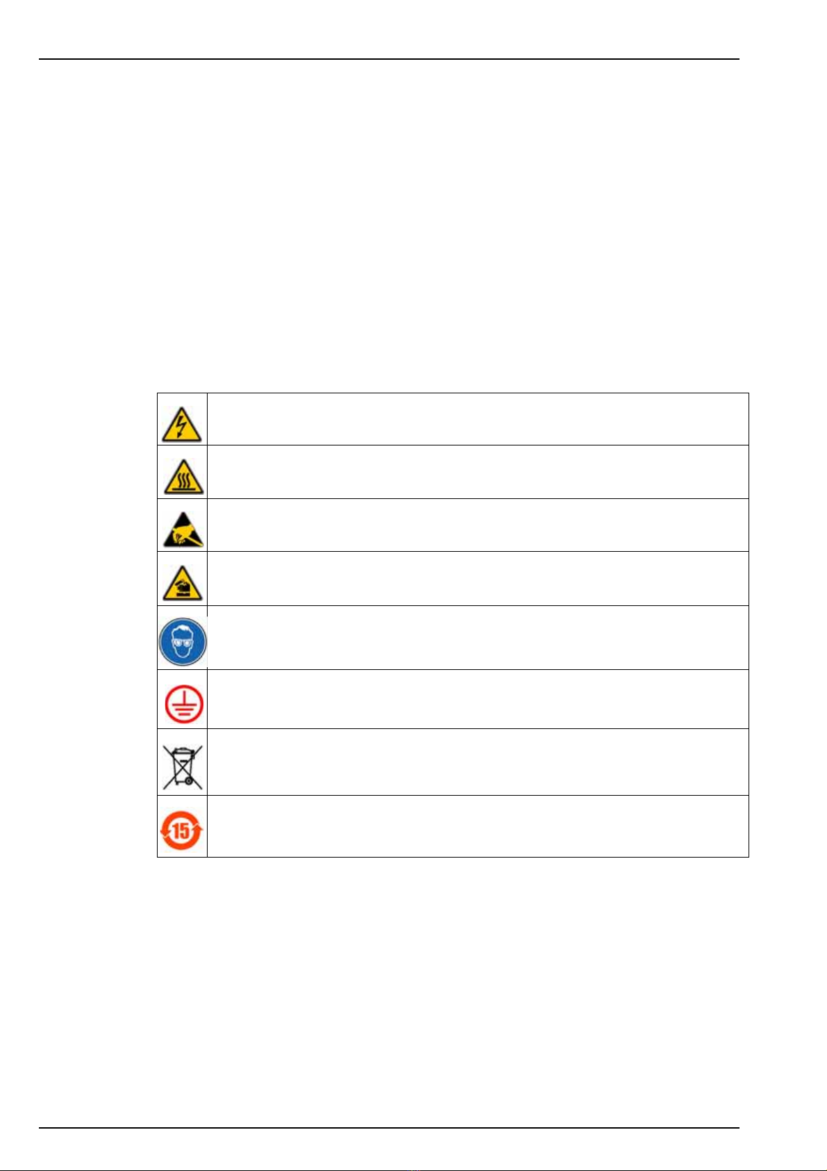
1.2.4 Precautionary labels............................................................................................................ 6
1.3 Product recycling information....................................................................................................... 7
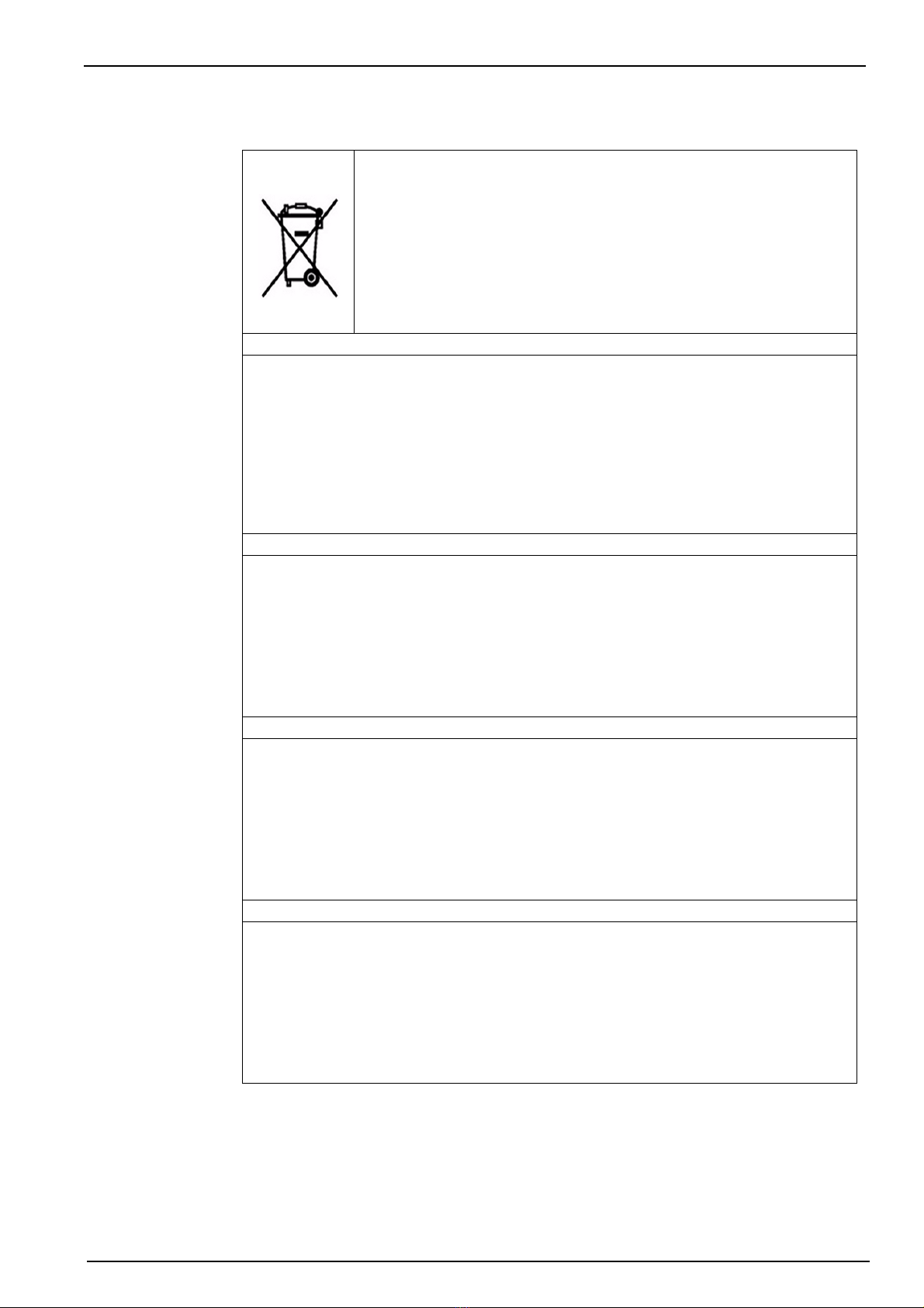
1.4 Product disposal .......................................................................................................................... 9
1.5 Restriction of hazardous substances (RoHS) ............................................................................ 10
Section 2 Specifications.................................................................................................................. 11
2.1 Technical specifications ............................................................................................................. 11
Section 3 Analyzer Overview ......................................................................................................... 13
3.1 Operation ................................................................................................................................... 13
3.2 Calibration.................................................................................................................................. 14
3.3 Analyzer outputs ........................................................................................................................ 14
3.4 Maintenance .............................................................................................................................. 14
3.5 Presentation............................................................................................................................... 15
3.5.1 Front panel........................................................................................................................ 15
3.5.2 Rear panel......................................................................................................................... 16
Section 4 Installation........................................................................................................................ 17
4.1 Analyzer inspection and unpacking ........................................................................................... 17
4.2 Analyzer preparation.................................................................................................................. 17
4.3 Installation checklist ................................................................................................................... 17
4.4 Mounting the analyzer................................................................................................................ 18
4.4.1 Panel version .................................................................................................................... 18
4.4.2 Cabinet version ................................................................................................................. 19
4.5 Installing the canister holder ...................................................................................................... 20
4.6 Connecting the sample .............................................................................................................. 21
4.7 Connecting the drain tube.......................................................................................................... 22
4.8 Mains power connection ............................................................................................................ 22
4.9 External communications connection ........................................................................................ 26
4.10 Input/Output connections ......................................................................................................... 27
4.11 Reagent preparation ................................................................................................................ 29
4.11.1 Reagent 1M - Molybdate (2 liters)................................................................................... 29
4.11.2 Reagent 1A - Nitric acid (2 liters) .................................................................................... 29
4.11.3 Reagent 2 - Oxalic acid...................................................................................................29
4.11.4 Reagent 3 - Reducing reagent ........................................................................................ 30
4.11.5 Calibration solution.......................................................................................................... 30
4.12 Connecting the canisters ......................................................................................................... 31
4.13 Analyzer startup ....................................................................................................................... 32
4.13.1 Reagents volume declaration.......................................................................................... 32
4.13.2 Flow rate adjustment....................................................................................................... 32
4.13.3 System and user setup procedures ................................................................................ 32
Section 5 Operating Instructions.................................................................................................. 33
5.1 Data Entry .................................................................................................................................. 33
5.1.1 Function Keys ................................................................................................................... 33
5.1.2 Modification of a value ...................................................................................................... 33
5.2 Measurement screens ............................................................................................................... 33
5.2.1 Main screen....................................................................................................................... 33
5.2.2 Display screen 2 - Measurement history........................................................................... 34
5.2.3 Display screen 3 - Alarms .................................................................................................34
5.2.4 Display screen 4 - Graph ..................................................................................................34
5.3 Main menu ................................................................................................................................. 35

2
Table of Contents
5.4 Analyzer menu overview ............................................................................................................36
Section 6 System Setup...................................................................................................................37
6.1 Menu overview ...........................................................................................................................37
6.1.1 Time ..................................................................................................................................37
6.1.2 Display...............................................................................................................................38
6.1.3 Code..................................................................................................................................38
6.1.4 Soft issues.........................................................................................................................39
6.1.5 Default values....................................................................................................................39
6.1.6 mA adjustments.................................................................................................................39
6.1.7 Factory ..............................................................................................................................40
Section 7 User Setup........................................................................................................................41
7.1 Measure menu overview ............................................................................................................41
7.1.1 Measuring mode................................................................................................................41
7.1.2 Grab sample......................................................................................................................42
7.1.3 Historic ..............................................................................................................................42
7.1.4 ADC values .......................................................................................................................43
7.2 Alarms menu overview...............................................................................................................43
7.2.1 Alarms 1 to 6 .....................................................................................................................44
7.2.2 Warning alarm ...................................................................................................................45
7.2.3 System alarm ....................................................................................................................45
7.2.4 Alarm conditions................................................................................................................46
7.3 mA outputs menu overview........................................................................................................47
7.3.1 Affect .................................................................................................................................47
7.3.2 Special programming ........................................................................................................48
7.3.3 Test ...................................................................................................................................49
7.4 RS485 ........................................................................................................................................49
7.5 Sequence ...................................................................................................................................50
7.5.1 Channel activation.............................................................................................................50
7.5.2 Sequence ..........................................................................................................................50
Section 8 Calibration........................................................................................................................51
8.1 Menu overview ...........................................................................................................................51
8.1.1 Programming (automatic calibration) ................................................................................52
8.1.2 Execution primary calibration ............................................................................................53
8.1.3 Execution manual calibration ............................................................................................53
8.1.4 Parameters........................................................................................................................54
8.1.5 Historic ..............................................................................................................................54
8.1.6 Calibration results..............................................................................................................55
Section 9 Maintenance.....................................................................................................................57
9.1 General.......................................................................................................................................57
9.2 Cleaning overview......................................................................................................................57
9.2.1 General cleaning process..................................................................................................57
9.2.2 Chemical cleaning procedure............................................................................................58
9.3 Battery replacement ...................................................................................................................59
9.4 Fuse replacement.......................................................................................................................59
9.5 Yearly maintenance....................................................................................................................60
9.6 Maintenance menu overview......................................................................................................63
9.7 Startup........................................................................................................................................64
9.8 Reagents refill ............................................................................................................................64
9.9 Extended stop ............................................................................................................................65
9.10 Tube cleaning...........................................................................................................................65
9.11 Photometer test........................................................................................................................66
9.12 Pumps - others.........................................................................................................................66
9.13 Pumps flowrate.........................................................................................................................66

3
Table of Contents
9.14 Solenoid valves........................................................................................................................ 67
9.15 Relays ...................................................................................................................................... 67
9.16 Logical inputs ........................................................................................................................... 67
9.17 Preparation of the tubes for insertion in the fast connectors.................................................... 68
Section 10 Troubleshooting........................................................................................................... 69
10.1 Possible sources of the problem.............................................................................................. 69
10.2 Possible solutions .................................................................................................................... 69
10.3 Typical measurement values during calibration....................................................................... 70
Section 11 Spare Parts..................................................................................................................... 71
Section 12 Default Configuration.................................................................................................. 73
Section 13 Material Safety Data Sheets (MSDS)........................................................................ 77
13.1 Oxalic acid ............................................................................................................................... 77
13.2 Sulfuric acid (98%)................................................................................................................... 78
13.3 Nitric acid (50-70%) ................................................................................................................. 80
13.4 Ammonium hydroxide (10-35% NH3) ...................................................................................... 84
13.5 Sodium hexafluorosilicate ........................................................................................................ 88
13.6 Ferrous ammonium sulfate hexahydrate ................................................................................. 89
13.7 Sodium molybdate dihydrate ................................................................................................... 91
13.8 Reagent R1A ........................................................................................................................... 92
13.9 Reagent R1M........................................................................................................................... 94
13.10 Reagent R2............................................................................................................................ 96
13.11 Reagent R3............................................................................................................................ 98
13.12 Lithium battery safety precautions ....................................................................................... 100

4
Table of Contents

5
Section 1 General Information
1.1 Disclaimer
The information in this manual has been carefully checked and is believed to be accurate.
However, Hach Lange assumes no responsibility for any inaccuracies that may be contained in
this manual. In no event will Hach Lange be liable for direct, indirect, special, incidental, or
consequential damages resulting from any defect or omission in this manual, even if advised of
the possibility of such damages. In the interest of continued product development, Hach Lange
reserves the right to make improvements in this manual and the products it describes at any
time, without notice or obligation.
Copyright © 2009 by Hach Lange. All rights reserved. No part of the contents of this manual
may be reproduced or transmitted in any form or by any means without the written permission of
Hach Lange.
1.2 Safety information
Read this entire manual before unpacking, setting up or operating this equipment. Pay attention
to all danger and caution statements. Failure to do so could result in serious injury to the
operator or damage to the equipment.
To make sure that the protection provided by this equipment is not impaired, do not use or install
this equipment in any manner other than that specified in this manual.
Note: This equipment has been tested and found to comply with the limits for Class A digital device,
pursuant to Part 15 of the FCC Rules. These limits are designed to provide reasonable protection against
harmful interference when the equipment is operated in a commercial environment. This equipment
generates, uses, and can radiate radio frequency energy and, if not installed and used in accordance with
the instruction manual, may cause harmful interference to radio communications. Operation of this
equipment in a residential area is likely to cause harmful interference in which case the user will be required
to correct the interference at his own expense.
1.2.1 Use of hazard information
WARNING
A warning is used to indicate a condition which, if not met, could cause serious personal
injury and/or death. Do not move beyond a warning until all conditions have been met
CAUTION
A caution is used to indicate a condition which, if not met, could cause minor or
moderate personal injury and/or damage to the equipment. Do not move beyond a
caution until all conditions have been met.
Note: A note is used to indicate important information or instructions that should be considered
before operating the equipment.
1.2.2 Safety recommendations
For safe operation, it is imperative that these service instructions be read before use and that
the safety recommendations mentioned herein be scrupulously respected. If repairs or
adjustments are necessary, the analyzer should be returned to an authorized Hach Lange
service center.
If danger warnings are not heeded to, serious material or bodily injury could occur.
WARNING
In accordance with safety standards, it must be possible to disconnect the power supply
of the analyzer in its immediate vicinity.
WARNING
The installation of the analyzer should be performed exclusively by personnel
specialized and authorized to work on electrical installations, in accordance with relevant
local regulations.

6
General Information
1.2.3 Service and repairs
None of the analyzer’s components can be serviced by the user. Only personnel from Hach
Lange or its approved representative(s) is (are) authorized to attempt repairs to the system and
only components formally approved by the manufacturer should be used. Any attempt at
repairing the analyzer in contravention of these principles could cause damage to the analyzer
and corporal injury to the person carrying out the repair. It renders the warranty null and void
and could compromise the correct working of the analyzer and the electrical integrity or the CE
compliance of the analyzer.
If you have any problems with installation, starting, or using the analyzer please contact the
company that sold it to you. If this is not possible, or if the results of this approach are not
satisfactory, please contact the manufacturer’s Customer Service.
1.2.4 Precautionary labels
Read all labels and tags attached to the analyzer. Personal injury or damage to the analyzer
could occur if not observed.
This symbol, when noted on a product enclosure or barrier, indicates that a risk of electrical
shock and/or electrocution exists and indicates that only individuals qualified to work with
hazardous voltages should open the enclosure or remove the barrier.
This symbol, when noted on the product, indicates that the marked item can be hot and should
not be touched without care.
This symbol, when noted on the product, indicates the presence of devices sensitive to
electrostatic discharge and indicates that care must be taken to prevent damage to them.
This symbol, when noted on the product, identifies a risk of chemical harm and indicates that
only individuals qualified and trained to work with chemicals should handle chemicals or perform
maintenance on chemical delivery systems associated with the equipment.
This symbol, if noted on the product, indicates the need for protective eye wear.
This symbol, when noted on the product, identifies the location of the connection for protective
earth (ground).
Electrical equipment marked with this symbol may not be disposed of in European public
disposal systems. In conformity with European local and national regulations, European
electrical equipment users must now return old or end-of-life equipment to the manufacturer for
disposal at no charge to the user.
Products marked with this symbol indicates that the product contains toxic or hazardous
substances or elements. The number inside the symbol indicates the environmental protection
use period in years.

7
General Information
1.3 Product recycling information
ENGLISH
Electrical equipment marked with this symbol may not be disposed of in
European public disposal systems after 12 August 2005. In conformity with
European local and national regulations (EU Directive 2002/96/EC), European
electrical equipment users must now return old or end-of-life equipment to the
manufacturer for disposal at no charge to the user.
Note: For return for recycling, please contact the equipment
manufacturer or supplier for instructions on how to return end-of-life
equipment for proper disposal.
DEUTSCH
Elektrogeräte, die mit diesem Symbol gekennzeichnet sind, dürfen in Europa nach dem 12.
August 2005 nicht mehr über die öffentliche Abfallentsorgung entsorgt werden. In
Übereinstimmung mit lokalen und nationalen europäischen Bestimmungen (EU-Richtlinie
2002/96/EC), müssen Benutzer von Elektrogeräten in Europa ab diesem Zeitpunkt alte bzw. zu
verschrottende Geräte zur Entsorgung kostenfrei an den Hersteller zurückgeben.
Hinweis: Bitte wenden Sie sich an den Hersteller bzw. an den Händler, von dem Sie das Gerät
bezogen haben, um Informationen zur Rückgabe des Altgeräts zur ordnungsgemäßen
Entsorgung zu erhalten.
FRANCAIS
A partir du 12 août 2005, il est interdit de mettre au rebut le matériel électrique marqué de ce
symbole par les voies habituelles de déchetterie publique. Conformément à la réglementation
européenne (directive UE 2002/96/EC), les utilisateurs de matériel électrique en Europe doivent
désormais retourner le matériel usé ou périmé au fabricant pour élimination, sans frais pour
l'utilisateur.
Remarque: Veuillez vous adresser au fabricant ou au fournisseur du matériel pour les
instructions de retour du matériel usé ou périmé aux fins d'élimination conforme.
ITALIANO
Le apparecchiature elettriche con apposto questo simbolo non possono essere smaltite nelle
discariche pubbliche europee successivamente al 12 agosto 2005. In conformità alle normative
europee locali e nazionali (Direttiva UE 2002/96/EC), gli utilizzatori europei di apparecchiature
elettriche devono restituire al produttore le apparecchiature vecchie o a fine vita per lo
smaltimento senza alcun costo a carico dell’utilizzatore.
Nota: Per conoscere le modalità di restituzione delle apparecchiature a fine vita da riciclare,
contattare il produttore o il fornitore dell’apparecchiatura per un corretto smaltimento.
DANSK
Elektriske apparater, der er mærket med dette symbol, må ikke bortskaffes i europæiske offentlige
affaldssystemer efter den 12. august 2005. I henhold til europæiske lokale og nationale regler
(EU-direktiv 2002/96/EF) skal europæiske brugere af elektriske apparater nu returnere gamle eller
udtjente apparater til producenten med henblik på bortskaffelse uden omkostninger for brugeren.
Bemærk: I forbindelse med returnering til genbrug skal du kontakte producenten eller
leverandøren af apparatet for at få instruktioner om, hvordan udtjente apparater bortskaffes
korrekt.

8
General Information
SVENSKA
Elektronikutrustning som är märkt med denna symbol kanske inte kan lämnas in på europeiska
offentliga sopstationer efter 2005-08-12. Enligt europeiska lokala och nationella föreskrifter
(EU-direktiv 2002/96/EC) måste användare av elektronikutrustning i Europa nu återlämna gammal
eller utrangerad utrustning till tillverkaren för kassering utan kostnad för användaren.
Obs! Om du ska återlämna utrustning för återvinning ska du kontakta tillverkaren av utrustningen
eller återförsäljaren för att få anvisningar om hur du återlämnar kasserad utrustning för att den ska
bortskaffas på rätt sätt.
ESPANOL
A partir del 12 de agosto de 2005, los equipos eléctricos que lleven este símbolo no deberán ser
desechados en los puntos limpios europeos. De conformidad con las normativas europeas
locales y nacionales (Directiva de la UE 2002/96/EC), a partir de esa fecha, los usuarios
europeos de equipos eléctricos deberán devolver los equipos usados u obsoletos al fabricante de
los mismos para su reciclado, sin coste alguno para el usuario.
Nota: Sírvase ponerse en contacto con el fabricante o proveedor de los equipos para solicitar
instrucciones sobre cómo devolver los equipos obsoletos para su correcto reciclado.
NEDERLANDS
Elektrische apparatuur die is voorzien van dit symbool mag na 12 augustus 2005 niet meer
worden afgevoerd naar Europese openbare afvalsystemen. Conform Europese lokale en
nationale wetgegeving (EU-richtlijn 2002/96/EC) dienen gebruikers van elektrische apparaten
voortaan hun oude of afgedankte apparatuur kosteloos voor recycling of vernietiging naar de
producent terug te brengen.
Nota: Als u apparatuur voor recycling terugbrengt, moet u contact opnemen met de producent of
leverancier voor instructies voor het terugbrengen van de afgedankte apparatuur voor een juiste
verwerking.
POLSKI
Sprzęt elektryczny oznaczony takim symbolem nie może byćlikwidowany w europejskich
systemach utylizacji po dniu 12 sierpnia 2005. Zgodnie z europejskimi, lokalnymi i państwowymi
przepisami prawa (Dyrektywa Unii Europejskiej 2002/96/EC), użytkownicy sprzętu elektrycznego
w Europie musząobecie przekazywaćProducentowi stary sprzęt lub sprzęt po okresie
użytkowania do bezpłatnej utylizacji.
Uwaga: Aby przekazaćsprzęt do recyklingu, należy zwrócićsiędo producenta lub dostawcy
sprzętu w celu uzyskania instrukcji dotyczących procedur przekazywania do utylizacji sprzętu po
okresie użytkownia.
PORTUGUES
Qualquer equipamento eléctrico que ostente este símbolo não poderá ser eliminado através dos
sistemas públicos europeus de tratamento de resíduos sólidos a partir de 12 de Agosto de 2005.
De acordo com as normas locais e europeias (Directiva Europeia 2002/96/EC), os utilizadores
europeus de equipamentos eléctricos deverão agora devolver os seus equipamentos velhos ou
em fim de vida ao produtor para o respectivo tratamento sem quaisquer custos para o utilizador.
Nota: No que toca à devolução para reciclagem, por favor, contacte o produtor ou fornecedor do
equipamento para instruções de devolução de equipamento em fim de vida para a sua correcta
eliminação.

9
General Information
1.4 Product disposal
Note: The following only applies to European customers.
Hach Lange is committed to ensuring that the risk of any environmental damage or pollution
caused by any of its products is minimized as far as possible. The European Waste Electrical
and Electronic Equipment (WEEE) Directive (2002/96/EC) that came into force on August 13
2005 aims to reduce the waste arising from electrical and electronic equipment; and improve the
environmental performance of all those involved in the life cycle of electrical and electronic
equipment.
In conformity with European local and national regulations (EU Directive 2002/96/EC stated
above), electrical equipment marked with the above symbol may not be disposed of in
European public disposal systems after 12 August 2005.
Hach Lange will offer to take back (free of charge to the customer) any old, unserviceable or
redundant analyzers and systems which carry the above symbol, and which were originally
supplied by Hach Lange. Hach Lange will then be responsible for the disposal of this
equipment.
In addition, Hach Lange will offer to take back (at cost to the customer) any old, unserviceable
or redundant analyzers and systems which do not carry the above symbol, but which were
originally supplied by Hach Lange. Hach Lange will then be responsible for the disposal of this
equipment.
Should you wish to arrange for the disposal of any piece of equipment originally supplied by
Hach Lange, please contact your supplier or our After Sales Service department in Geneva for
instructions on how to return this equipment for proper disposal.

10
General Information
1.5 Restriction of hazardous substances (RoHS)
The European Union RoHS Directive and subsequent regulations introduced in member states
and other countries limits the use of six hazardous substances used in the manufacturing of
electrical and electronic equipment.
Currently, monitoring and control instruments do not fall within the scope of the RoHS Directive,
however Hach Lange has taken the decision to adopt the recommendations in the Directive as
the target for all future product design and component purchasing.
Note: The following only applies to exports of this product into the People’s Republic of China.
Transmitter box X
CPU PCB
(with battery) OO
Power PCB O O
RS 485 O
Profibus O
PCB CAN O
PCB Local controller O
PCB Measure O
PCB Pumps O
PCB Mixer O
PCB Channel O
O:
X:

11
Section 2 Specifications
2.1 Technical specifications
Specifications are subject to change without notice.
Sample
Number of channels 1 - 6
Measurement cycle < 10 min / channel
Sample pressure 0.2 to 6 bar (3 to 87 psi)
Temperature 5 - 50°C (41 - 122°F)
Sample flow Minimum 5L / hour
Maximum 30L / hour
Connections
Sample input Simple fittings for 6 mm O.D. tubing or ¼" O.D. in PE-low density.
¼" OD in PHED-PTFE-SS as option
Sample output Barbed stem for 12 mm (½" I.D.) hose
Conditions of use
Ambient temperature 5 to + 45°C (41 to 113°F)
Power supply voltage fluctuation ± 10%
Overvoltage category 2 (according to standard EN 61010-1)
Degree of pollution 2 (according to CEI 664)
Altitude ≤ 2000 m
Relative humidity 10 to 80%
Measurement category Cat II, Class 1 (overvoltage < 1500V)
Weight
Panel analyzer without canister 13 kg
Cabinet analyzer without canister 65 kg
Full canisters 8 kg
Standards
EMC EN 61326-1 (1997) & A1 (1998) & A2 (2001) & A3 (2004)
European safety standards IEC 61010-1 (2001) & EN 61010-1 (2001)
UL & CSA agreement Certified to UL & CSA safety standards, with cETLus mark
(Control Number: 3164002)
UL & CSA standards
Safety of Electrical Equipment for Measurement, Control and Laboratory use;
UL61010-1, Issued: 2004/07/12, Ed.2 Rev: 2005/07/22 and CAN/CSA C22.2
No. 61010-1, Issued: 2004/07/12
Analysis
Value measured Dissolved SiO2
Cycle time Approximately 10 minutes per channel
Measurement range (2 versions) 0 - 1000 ppb 0 - 5000 ppb
Repeatability ± 2% or ± 0.5 ppb ± 2% or ± 2 ppb
Detection limit 0.5 ppb 2 ppb

12
Specifications
Inputs / Outputs
Alarms
Number 8
Functions 6 threshold alarms / lack of sample / active channel
1 system alarm
1 warning alarms
Cut-off power 30 VDC, 0.5 A maximum
Logical inputs
Number 12
Remote alarm clearance
By-pass measurement for a channel
Serial input interface RS 485, Modbus communication protocol
Outputs 4 / 20 mA
Number 8
4/20 mA or 0/20 mA programmable
Galvanically insulated
Maximum charge of 800 ohms
Materials and protection
Transmitter Aluminium with polyester paint
Panels and other boxes Polystyrene
Protection transmitter box IP 65
Protection cabinet (optional) IP 54
Cabinet front door Plexiglas
Maintenance
Calibration Chemical zero, slope with calibration solution
Maintenance No particular maintenance is necessary
Cleaning can be done with a soft non-aggressive cloth
Reagent consumption Approximately 1L per month and per reagent
Calibration solution consumption Approximately 200 ml / calibration
Time safeguard lithium battery CR 1220 (3 V)
Transmitter
Display
Programming by menu
Concentration of 6 samples
Analyzer status
Alarms
Trend curves
Concentration historic
Calibration parameters historic (date, slope and offset)
Mains power supply
Mains
100 - 240 VAC 50 - 60 Hz
Automatic switching
Max. consumption: 80 VA

13
Section 3 Analyzer Overview
3.1 Operation
The 9210 can analyze up to six different samples. The sample to be analyzed circulates in a
fast loop permitting rapid renewal of the sample. Adjustment of the flow is carried out with the
help of a needle valve (2). At the beginning of the analysis, the sample is introduced into the
measuring cell (4) with the use of a solenoid valve (5).
The reagents R1M and R1A are first added using two of the reagent pumps (9). The silica
contained in the sample then reacts with the molybdate and forms the silicomolybdic complex.
The reaction will take up to 5 minutes.
Oxalic acid is then added using a reagent pump (9) to avoid phosphate interference and to
intensify the color.
The silicomolybdic complex is reduced to a blue molybdenum complex by means of ferrous
ions. A photometric measurement is carried out at the end of the reaction.
Figure 1 Working principal
1 - Overflow tank with level detector 6 - Mixing motor 11 - Calibration pump
2 - Flow adjustment valves (1 to 6) 7 - Magnetic bar 12 - Calibration solution canister
3 - Sample input (1 to 6) 8 - Drain 13 - Photometer
4 - Photometric measuring cell 9 - Reagent pumps (x4) 14 - Drain pump of measuring cell
5 - Measuring solenoid valve 10 - Reagent canisters (x4)

14
Analyzer Overview
3.2 Calibration
In order to ensure accurate measurements, the analyzer should be calibrated periodically. The
zero is achieved chemically and internally in the analyzer. The system slope is controlled by
comparison to a standard solution of known concentration. Further information regarding
calibrations can be found in the section entitled Calibration on page 51.
3.3 Analyzer outputs
The instrument can measure silica concentration from three different sources:
•the process sample during a normal measuring cycle
•the calibration solution during an automatic calibration
•an external sample during the grab sample operation
Whatever the sample source, the measurement cycle structure is identical and all analyzer
outputs (e.g. 4/20 mA outputs, screen display, RS485 data, alarm status, etc.) are refreshed
during the last minute of the measurement.
3.4 Maintenance
To ensure a high degree of accuracy is maintained by the analyzer, it is recommended to
perform a specific maintenance procedure once a year. All replacement parts and fittings are
available by purchasing the maintenance kit 09120=A=8000 which contains enough parts and
fittings for two years.
Full details on this procedure and the contents of the maintenance kit can be found in Yearly
maintenance on page 60.

15
Analyzer Overview
3.5 Presentation
3.5.1 Front panel
Figure 2 Analyzer front panel
1 - Transmitter box 4 - Sample 1 to 6 flow adjustment valves
2 - Sample level detector 5 - Photometric measurement cell
3 - Overflow vessel

16
Analyzer Overview
3.5.2 Rear panel
Figure 3 Analyzer rear panel
6 - Local controller box 9 - Measurement box
7 - Measurement solenoid valve 10 - Sample inlet valves
8 - Pumps box 11 - Drain

17
Section 4 Installation
WARNING
The analyzer should only be assembled by qualified staff. Mains power should only be
connected once installation has been completed and checked.
4.1 Analyzer inspection and unpacking
The analyzer has been factory tested and checked prior to shipping. We nevertheless
recommend that you perform a visual inspection in order to ensure that it has not been
damaged. Any marked packaging is a potential sign of damage that may not be immediately
visible. Keep all packaging in the event of claims.
Open the box. Take the packing list from the box and check the presence of all the items
selected. If any parts or accessories are missing, refer to your distributor or to Hach Lange.
4.2 Analyzer preparation
Before installing the analyzer, think about the following:
•Place the analyzer close to the sample point. This will allow the response time to be reduced.
•The sample should be homogenous and representative.
•The temperature of the sample should be between 5 and 50°C.
•The pressure of the sample should be between 0.2 and 6 bar and remain relatively stable.
•The solution should be free of particles.
•Sample lines should be in PE/PTFE/FEP (4 x 6 mm).
•Avoid any location with a corrosive atmosphere or subject to liquid spills.
•Chose a dry and dust-free location.
•The ambient temperature of the analyzer should not exceed 45°C. If the temperature is
below 5°C, the analyzer should be installed in a heated cabinet (not provided by Hach
Lange).
4.3 Installation checklist
For a complete installation, perform the following actions in the order specified, following the
instructions very carefully:
1. Mount the analyzer - section 4.4 on page 18
2. Install the canister holder - section 4.5 on page 20
3. Connect the sample lines - section 4.6 on page 21
4. Connect the drain tube - section 4.7 on page 22
5. Connect the mains power - section 4.8 on page 22
6. Connect the external communications - section 4.9 on page 26
7. Input/Output connections - section 4.10 on page 27
8. Reagent preparation - section 4.11 on page 29
9. Connect reagent canisters - section 4.12 on page 31
10. Analyzer stabilization and startup - section 4.13 on page 32

18
Installation
4.4 Mounting the analyzer
CAUTION
Wherever the analyzer is to be mounted, it is important to note that it must be placed in
an upright position with the transmitter at the top. It is recommended to use a spirit level
to ensure that the analyzer is correctly positioned and not leaning to one side or forward.
This is essential to guarantee the accuracy of the analyzer.
4.4.1 Panel version
For the panel version, the dimensions of the analyzer and fixation holes are shown in Figure 4.
A. Mains power supply cable gland, drilled ∅ 11 (5 to 10mm), 100…240V, 50-60Hz, 25VA
B. Field bus cable gland, drilled ∅ 13 (6 to 12mm)
C. 5 to 7 mm cable gland
•Alarm signals: 30V, 0.5A max.
•Logic inputs: Cutoff on channels 1 to 6, acknowledgement of alarm signals
•Analog outputs: 0-20 mA or 4-20 mA
D. Sample inlets, (channels 1 to 6), QR coupling for semi-rigid tubing ∅ 6mm, 5 to 50°C
(40° to 120°F), P 0.2 to 6 bar (3 to 87 PSI)
E. Drain tube: silicon tubing ∅ 12 x 17mm, at atmospheric pressure
Figure 4 Panel version dimensions - mm [ins]
Table of contents
Other Polymetron Measuring Instrument manuals