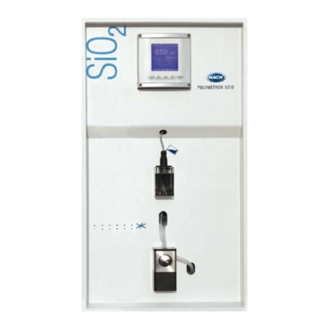
Polymetron SODIMAT 9073 User manual

SODIMAT
Model 9073
Instruction manual
03/2001 621=190=073
Rev. D


This instrument conforms to the European Directives:
- 89/336/CEE modified by the directive 93/68/CEE
- 73/23/CEE modified by the directive 93/68/CEE

SODIMAT - Model 9073
COPYRIGHT
Allrightsreserved. No part of thispublication may be
reproduced, stored inaretrieval system, ortransmitted, inany
form or by any means, electronic, mechanical, photocopying,
recording or otherwise, without prior permission of
Polymetron S.A.
Polymetron S.A.
Polymetron S.A. can take no responsabilityfor
installation and/oruse of its equipment if thisisnot donein
accordance with the appropriate issueand/oramendment of
the relevant manual.
The user of this manualshould ensure that it isappropriate
inall details to the exact equipment to beinstalled and/or
operated. If indoubt, theuser should contact
Polymetron S.A. for advice.
WARNING
Tomaintain safety standards, regular maintenance,
calibration and operation of thisequipment byqualified
personnel isessential. Read andunderstand
Instruction manual completelybefore operating or
servicing. If anyfurther detailsare required which do
notappear in this manual contact Polymetron S.A. or
their agent.

SODIMAT - Model 9073
ii
Table of contents
Chapter 1 : Introduction ................................................ 1-1
1.1.Introduction .................................................. 1-1
1.2 Applications .................................................. 1-1
1.3 Technical characteristics ........................................ 1-2
1.4 Drawing ..................................................... 1-5
Chapter 2 : Description of the analyser .................................... 2-1
2.1 Principle of operation .......................................... 2-1
2.2 Analytical part - AUTOCAL version ................................ 2-3
2.3 Analytical part - CARCAL version ................................. 2-5
2.4 Electronics ................................................... 2-7
Chapter 3 : Installation ................................................. 3-1
3.1 Unpacking ................................................... 3-1
3.2 Inspection ................................................... 3-1
3.3 Mounting .................................................... 3-1
3.4 Location .................................................... 3-1
3.5 Hydraulic connections .......................................... 3-2
3.5.1 CARCAL version ....................................... 3-2
3.5.2 AUTOCAL version ..................................... 3-2
3.5.3 mixed bed option ...................................... 3-2
3.5.4 liquid conditioning option ................................ 3-2
3.6 Electrical connections .......................................... 3-2
3.7 Mounting the electrodes ........................................ 3-8
3.7.1 Measuring electrode .................................... 3-8
3.7.2 Reference electrode .................................... 3-8
3.8 Flooding and starting the analyser ............................... 3-10
3.9 pH adjustment ............................................... 3-10
Chapter 4 : Operating the intrument ...................................... 4-1
4.1 Front panel displays ........................................... 4-1
4.2 Front panel keyboard .......................................... 4-2
4.3 Rollkeys in the measurement mode ............................... 4-2
4.4 Displaying or altering programmed parameters ....................... 4-2

SODIMAT - Model 9073
iix
Chapter 5 : Programming ............................................... 5-1
5.1 General configuration and calibrations ............................. 5-2
5.2 Alarm configuration ............................................ 5-4
5.3 Analogue output configuration ................................... 5-6
5.4 Serial interface configuration .................................... 5-8
5.5 Use of the interface RS232 ..................................... 5-10
55.6 Function parameter configuration ................................ 5-12
Chapter 6 : Calibrating the instrument .................................... 6-1
6.1 Calibration of the flowmeter ..................................... 6-1
6.2 Calibration of the temperature sensor .............................. 6-1
6.2.1 Temperature automatic compensation ...................... 6-1
6.2.2 Temperature manual compensation ........................ 6-2
6.3 Measurement calibration ........................................ 6-2
6.3.1 CARCAL calibration .................................... 6-3
6.3.2 AUTOCAL calibration ................................... 6-4
6.3.3 Manual calibration ...................................... 6-7
6.3.4 Process calibration ..................................... 6-7
Chapter 7 : Maintenance ................................................ 7-1
7.1 Normal operating maintenance ................................... 7-1
7.2 Specific operating maintenance .................................. 7-1
7.2.1 Electrode slope loss .................................... 7-1
Chapter 8 : Troubleshooting ............................................ 8-1
8.1 Error messages ............................................... 8-1
8.2 Acknowledgment .............................................. 8-1
Chapter 9 : Troubleshootings, causes ans solutions ......................... 9-1
Chapter 10 : Options .................................................. 10-1
10.1 Mixed bed option ............................................ 10-1
10.2 Liquid conditioning option (kit K) ................................ 10-5
10.2.1 Generality .......................................... 10-5
10.2.2 Putting into service ................................... 10-6
Appendix A : Spare parts list ........................................... A1-1
Appendix B : Configuration table for the user ............................. B1-1
Appendix C : Safety data sheet ......................................... C1-1
C.1 Diisopropylamine ............................................. C-1
C.2 Hydrofluoric acid .............................................. C-3
C.3 Ammonia solution ............................................. C-5
C.4 Ethanolamine ................................................ C-7

E'' E0%% R((T
F(( lnk CNa%%
SODIMAT - Model 9073
1-1
Chapter 1 : Introduction
1.1 Introduction
The SODIMAT - Model 9073 permits the
measurement of sodium in industrial
ultrapure waters.
The measurement is based on a direct
potentiometric technique using a highly
sensitive sodium glass electrode. The
difference of potential between the glass
electrode and the reference electrode is
directly proportional to the sodium
concentration as shown by the Nernst law:
1.2 Applications
Modern high-pressure power plants require
feedwater of very high purity. Safety in that
sector is of great importance and the
sodium measurement plays a specific role
compared to pH, conductivity and silica
trace.
Actually, sodium cations and anions are
always linked. Most cations have a
corrosive influence in water and vapor
cooling circuits.
Because of this chemical link between
sodium ions and anions, sodium
measurement presents particularly
important risks of corrosion and other
effects.
The presence of chlorides, for example,
involves corrosion under power and when it
exceeds allowable concentration limits.
// Main features of the SODIMAT - Model
9073
3Sample flow rate control
3A microprocessor controlled temperature
compensation
3Panel or cabinet mounting possibilites
3Two versions depending on the
calibration method chosen :
-AUTOCAL : automatic calibration by
addition of sodium known concentration
solution
-CARCAL : calibration using calibration
cartridges of 20 and 200 ppb.

SODIMAT - Model 9073
1-2
1.3 Technical characteristics
SAMPLE
Number of channels 1
Insolubles Free of undissolved matter : turbidity < 2
NTU
Temperature 5...45 C (41...113 F)
B B
Pressure 0,5-6 bar (1-6 bar in CARCAL version)
Output Atmospheric pressure
Flow rate 3-6 l/h
CONNECTIONS
Mains 240 - 220 - 110 - 24 V
- 15% to +10%, 50-60 Hz
Power consumption 50 VA
Terminal - Screw terminal (1 mm cable) for the input
2
and output signals
-Spring loaded terminal (1 mm cable) for
2
mains, alarm, limits and alarm quit
Sample 4/6 mm tubing
ANALYSIS
Measuring range 0,01 ppb to 10,000 ppm programmable
Accuracy ± 5% or <±0.05 ppb whichever is greater
Reproducibility ± 3% or <±0.03 ppb whichever is greater
Response time 1 ppm to 1 ppb (90%) < 10 min
100 ppb to 10 ppb (90%) < 2 min
Ambiant temperature 5...50 C
B
Conditioning reagent Gaseous : diisopropylamine advised,
ammoniac accepted
Liquid : éthanolamine 30 to 50%
Diisopropylamine consumption 1 l/month approx.
Calibration solution consumption 6calibrations per bottle (if 20 minutes by
calibration point)

SODIMAT - Model 9073
1-3
Calibration -Manual by 2 known concentration solutions
- Process on one point
2 versions possible :
-addition 1 or 2 points (CARCAL 20 and 200
ppb cartridges)
-automatic by dosing pump with a known
concentration solution ( 1 or 2 additions)
TRANSMITTER
Display 4 digit digital LCD , 18 mm-height, backlit
Display of the measurement unit : ppb, ppm,
mV, C or l/h, LED and the instrument status
B
: error, calibration, programming.
Output current 2 analogue outputs : 2 x 0/4... 20 mA isolated
from input signal, 900 Ohms load maximum
Relays 2isolated contacts, minimum or maximum
switchable
1 isolated contact for system alarm
250 VAC max., 5A max. or 1200 VA on a
resistive load
Temporisation On the concentration limits adjustable from 0
to 9999 seconds
Interface for computer RS 232/V24C ; 300, 600, 1200, 2400, 4800,
9600 bauds (programmable)
TRANSMITTER ENCLOSURE
Material ABS
Tightness IP65, according to norm IEC 529
Dimensions H 144 mm, W 144 mm, D 152 mm
Glands 4 x PG9 - 1 x PG13,5
Material : polyamide
Storage temperature -20...+70 C
B
Weight 1,7 kg
ENCLOSURE (OPTIONAL)
Standard 19" width for wall or panel
mounting
Material ABS with PMMA window
Connections 1 gland DN 6/8 for outlet
1 gland DN 4/6 for water input
1 x PG13,5 for mains
1 x PG13,5 for overflow output
6 x PG9 for different connections

SODIMAT - Model 9073
1-4
Weight 10,6 kg
ELECTROMAGNETIC COMPATIBILITY
Immunity to electromagnetic interferences EN 50082-2 and 50082-1
Electromagnetic emission EN 50081-1 and 50081-2
OPTIONS
Demineralization cartridge (mixed bed)
Kit K (liquid conditioning for high acidity
water)
Nota : Kit K and mixed bed are
incompatible together
ANALYSER WEIGHT
Analyser without enclosure 17,2 kg

SODIMAT - Model 9073
1-5
1.4 Drawing
Fixations :
- wall-mounting : 6 M6 screws
- 19" panel-mounting : 4 M6 screws
Figure 1-1 : Dimensions for the 9073 fixation


SODIMAT -Model 9073
2-1
Chapter 2 : Description of the analyser
2.1 Principle of operation
The SODIMAT 9073 uses a sodium-interferences by other ions, especially ions
sensitive glass electrode to measureH+. Low-level sodium measurements,
sodium in a sample which has beentherefore, require that the H+ of the sample
previously conditionned to a pH > 10.water be adjusted to a level several orders
Sample conditionning is necessary because of magnitude below the level of sodium. For
sodium glass electrodes are not perfectlythis reason, the SODIMAT 9073
specific sensors, but are subject to
Figure 2-1 :
Principle of operation of the 9073 - AUTOCAL version
1 : Filter 8 : Temperature sensor
2 : Flow rate regulator 9 : Measuring electrode
3 : Electronic flowmeter 10 : Reference electrode
4 : Calibration solution 11 : Output drain
5 : Calibration pump 12 : Transmitter MONEC 8941
6 : Conditioning reagent 13 : Adjusting valve
7 : Conditioning block

SODIMAT -Model 9073
2-2
Figure 2-2 : Principle of operation of the 9073 - CARCAL version
1 : Filter 7 : Temperature sensor
2 : Flow rate regulator 8 : Measuring electrode
3 : Electronic flowmeter 9 : Reference electrode
4 : CAR4CAL calibration solution 10 : Output drain
5 : Conditioning reagent 11 : Transmitter MONEC 8941
6 : Conditioning block 12 : Adjusting valve

SODIMAT -Model 9073
2-3
2.2 Analytical part - AUTOCAL version
Figure 2-3 : 9073 - Front panel - AUTOCAL version
1 : Transmitter MONEC 8941 7 : Calibration solution
2 : Electrolyte container 8 : Conditioning reagent
3 : Reference filler neck 9 : Flowrate adjustment valve
4 : Reference electrode 10 : Conditioning block
5 : Measuring electrode 11 : pH adjustment screw
6 : Measuring cell

SODIMAT -Model 9073
2-4
Figure 2-4 : 9073 rear
view - AUTOCAL version
1 : Electronic flowmeter 9 : Inlet sample tubing
2 : Flowrate regulator 10 : Output collector
3 : Flowrate adjusting valve 11 : Temperature sensor
4 : Calibration pump 12 : Filter
5 : Conditioning reagent 13 : Measuring preamplifier
6 : Calibration solution 14 : Electrolyte container
7 : Outgoing pipe 15 : Interface box
8 : Overflow tubing

SODIMAT -Model 9073
2-5
2.3 Analytical part - CARCAL version
Figure 2-5 : 9073 front view - CARCAL version
1 : Transmitter MONEC 8941 7 : Conditioning reagent
2 : Electrolyte container 8 : Flowrate adjustment valve
3 : Reference filler necks 9 : Calibration cartridge holder (CARCAL)
4 : Reference electrode 10 : Conditioning block
5 : Measuring electrode 11 : pH adjustment screw
6 : Measuring cell

SODIMAT -Model 9073
2-6
Figure 2-6 : 9073 rear view - CARCAL version
1 : Electronic flowmeter 8 : Output collector
2 : Flowrate regulator 9 : Temperature sensor
3 : Flowrate adjusting valve 10 : Filter
4 : Conditioning reagent 11 : Measuring preamplifier
5 : Outgoing pipe 12 : Electrolyte container
6 : Overflow drain 13 : Interface box
7 : Inlet sample tubing

SODIMAT -Model 9073
2-7
2.4 Electronics
To reach the interior of the instrument (for
electrical wirings, EPROM removal, power
supply control), remove the 4 front panel
screws, fixed to the microprocessor's board.
The electronics of the SODIMAT hold 3
printed circuits, 2 of them are located
behind the front panel :
#The display board with a liquid crystal
display, status LEDs, control keys and the
microprocessor.
#The analogue board including the
measurement module (sensors input) and
the analogue/numeric conversion unit.
#The third one is located behind the
protective cover in the main enclosure. It
includes the power module, the outputs, the
relays and the RS232 interface. In addition
it includes the terminal board connections
from 1 to 29.
Figure 2-7 : Circuit location in the MONEC 8941
1 : Display board 3 : Power supply board
2 : Terminals 4 : Measuring board

Table of contents
Other Polymetron Measuring Instrument manuals
Popular Measuring Instrument manuals by other brands

Shodex
Shodex HILICpak VN-50 4D Operation manual

Arbiter Systems
Arbiter Systems 1133A Quick setup guide

GE
GE SS-131ER Installation and operating instructions

EDTM
EDTM Glass-Chek ELITE GC3200 operating manual

Applent Instruments
Applent Instruments AT5108 user guide

Siemens
Siemens SICAM Q100 7KG95 Series manual

MED Associates
MED Associates ENV-421 user manual

Fieldpiece
Fieldpiece SC57 Operator's manual

Emerson
Emerson Rosemount 8600 Series quick start guide

Thermo Scientific
Thermo Scientific AQUAfast AQ3170 user guide

Morehouse
Morehouse 4215-HS Operation and instruction manual

kruss
kruss DS7000 Series user manual