manuals.online logo
Brands
  1. Home
  2. •
  3. Brands
  4. •
  5. Nikon
  6. •
  7. Measuring Instrument
  8. •
  9. Nikon NPL-352 User manual

Nikon NPL-352 User manual

FEMA US&R Response Sys/U.S. Army Corps of Engineers
STRUCTURES SPECIALIST SKILLS TRAINING October 2007
TST – Total Station Training
TOTAL STATION USE
FOR THE
STRUCTURAL SPECIALIST
October 13, 2007
Session 1-1 Basics of the NPL-352 and Theodolite Use
Classroom - 45 minutes
Session 1-2 Basic Field Set-up and Theodolite Use
Field - 60 minutes
Session 1-3 Initial Configuration and Basic EDM Use
Classroom - 60 minutes
Session 1-4 Basic Field Use of the EDM
Field - 60 minutes
Session 2-1 Advanced Use of Total Station
Classroom - 30 minutes
Session 2-2 Advanced Use of Total Station
Field - 120 minutes
Session 2-3 Use of Total Station for US&R
Classroom - 30 minutes
Measurement Basics and Theodolite Use Page 1
FEMA US&R Response Sys/U.S. Army Corps of Engineers
STRUCTURES SPECIALIST SKILLS TRAINING October 2007
TST – Total Station Training
Session 1-1 Measurement Basics and Theodolite Use
Basic Measurement Tools
Theodolite vs. Total Station
1) Theodolites measure horizontal and vertical angles.
2) Total Stations combine theodolites with the ability to measure distance.
3) Both can be used as simple point observation devices
Angular Measurement
Azimuth
Azimuth
• Horizontal plane
0o
•, 360o is straight ahead
00
• Angles are measured
clockwise
Azimuth Angle
00
Zenith Angle
Zenith
Zenith
• Vertical plane
0o
•is straight up, usually
• Angles are measured
down from vertical
Measurement Basics and Theodolite Use Page 2
FEMA US&R Response Sys/U.S. Army Corps of Engineers
STRUCTURES SPECIALIST SKILLS TRAINING October 2007
TST – Total Station Training
Distance Measurement
PT- A
PT- B
HD
HI SD
HT
VD
Instrument
Constant
Prism
Constant
(
P
C)
Prism

MD
HI = the height of the instrument (vertical distance from station point at Point A
to axis of telescope).
HT = the height of the target (vertical distance from measured point at Point B to
the prism).
MD = the distance measured by the EDM (measured distance from the total
station axis to the prism focus).
SD = the slope distance (computed distance along the inclined line from the
station point to the measured point).
= the angle of the instrument relative to horizontal (90o - Zenith Angle).
HD = the horizontal distance from the station point to the measured point.
VD = the vertical distance from the station point to the measured point.
PC = the prism constant, obtained from the manufacturer of the prism, usually
etched on the prism frame. Prisms have different constants (PC):
•Large prism = 30 mm (Not part of cache)
•Mini prism = 18mm
•Reflector sheet = 0 mm
•Prism-less = 0 mm
Instrument Constant = Property of the instrument set at the factory.
Measurement Basics and Theodolite Use Page 3
FEMA US&R Response Sys/U.S. Army Corps of Engineers
STRUCTURES SPECIALIST SKILLS TRAINING October 2007
TST – Total Station Training
Location Measurement In 3 Dimensions
The conventional survey coordinate order is
N E Z and the total station normally outputs
coordinates as N, E, Z:
•N is Northing (0oon the azimuth)
•E is Easting (90oto Northing)
•Z is elevation above N - E plane
Z
N
E
Total station can output coordinates as X, Y, Z,
but if the coordinate order is set to N E Z then:
X = N
Y = E
Z = Z
Z
X (N)
Y (E)
This is different from the normal engineering convention.
Z
To maintain the engineering convention, the
coordinate order should be set to E N Z so that:
Y (N)
X = E
Y = N
Z = Z
X (E)
Measurement Basics and Theodolite Use Page 4
FEMA US&R Response Sys/U.S. Army Corps of Engineers
STRUCTURES SPECIALIST SKILLS TRAINING October 2007
TST – Total Station Training
Location Measurement In US&R
Y (N)
Z BS
MP
(
x
,y,
z
)
CP
(
x
,y,
z
)
X (E)
IP (x,y,z)
MP = Monitoring Point IP = Instrument Point CP = Control Point
Current thinking for US&R is to set the X axis parallel to the side of the building
facing the instrument and the Y axis perpendicular to the building. To do this, a
location on the structure is used to set the azimuth angle to 0o(the instrument
refers to the point used to set the azimuth as the back sight, BS). The location
must be chosen such that the 0o azimuth is perpendicular to the side of the
building facing the instrument.
If creating a new coordinate grid, give the new station widely different
coordinates such as: X = 1000.00 Y = 3000.00 Z = 5000.00 Significantly
different coordinates are beneficial in the event that E, N, Z is mixed up with N,
E, Z. This difference helps the StS quickly translate a change in coordinates to
a magnitude and direction of movement.
Once established on a station, set several Control Points (CP):
1. They can be used as alternate instrument stations.
2. This allows options if some sites are blocked by equipment or if you need
to set up the instrument at a new remote location.
3. This allows choices if reestablishing the grid from a new location not
previously located by survey.
Measurement Basics and Theodolite Use Page 5
FEMA US&R Response Sys/U.S. Army Corps of Engineers
STRUCTURES SPECIALIST SKILLS TRAINING October 2007
TST – Total Station Training
Theodolite vs. Total Station
1. Theodolites measure horizontal and vertical angles
2. Total Stations combine theodolites with the ability to measure distance.
Infra-red Light Emitting Diode uses a continuous signal and measures the
shift between light emitted by the EDM and the reflected signal to measure
distance. A reflecting target such as a prism or reflector sheet is used.
Pulse Laser Diode transmits a timed-
pulse infrared signal and measures the time
required for the pulse of infrared light to travel
from the instrument to the target and back to
determine distance. A prism is not necessary,
however, this technology has limited distance
capability (about 300 feet).
Tools Contained in the Case
1) Nikon NPL-352
2) Mini Prism, Pole, and Tips
3) Batteries and Charger
4) Power Inverter
5) Shoulder Straps
6) User's Manual
7) Instrument Rain Cover
8) Right Angle Eyepiece:
The right angle eyepiece is used when sighting points at angles greater
than 45° to the horizontal. The existing eyepiece must be unscrewed from the
unit and placed onto the sighting end of the right angle eyepiece.
Measurement Basics and Theodolite Use Page 6
FEMA US&R Response Sys/U.S. Army Corps of Engineers
STRUCTURES SPECIALIST SKILLS TRAINING October 2007
TST – Total Station Training
The 2 Faces of the Nikon NPL-352
1) Face 1 of the instrument is the face
with the tangent screws.
Sighting Pointer
Telescope Focus Ring
Eyepiece Focus Ring
Vertical Tangent Screw
Plate Level
Horizontal Tangent Screw
Bulls-eyeLevel
Tangent screws are not endless Face 1
Face 2 of the instrument is with the
optical plummet eyepiece.
Carrying Handle
Battery
OpticalPlummet
PlummetFocus
CrosshairFocus
Leveling Screws
Face2
Measurement Basics and Theodolite Use Page 7
FEMA US&R Response Sys/U.S. Army Corps of Engineers
STRUCTURES SPECIALIST SKILLS TRAINING October 2007
TST – Total Station Training
Nikon NPL-352 Key Layout
Mode Menu
Level
Compensators
DisplayMeasure
Escape/Undo Record/Enter
Angle
Added Key Functions
1 - Second Keys
Certain keys have additional functions when pressed and held for one second or more.
Nikon refers to these as 1 - Second Keys. The MSR, DAT, DSP, USR and S-O keys are all
1-Second Keys. We will address the alternate functions of the keys in a later section of this
class.
Soft Keys
The MSR1, MSR2, DSP and ANG keys perform additional functions when certain screens
are displayed. These keys are referred to by Nikon as Soft Keys. For example, in the Job
Manager screen shown above, pressing the MSR1 key would perform the function Creat
displayed in the screen above it, creating a new job. Likewise pressing the MSR2 key would
DEL, deleting the highlighted job displayed on the screen. The other soft keys function
similarly.
Measurement Basics and Theodolite Use Page 8
FEMA US&R Response Sys/U.S. Army Corps of Engineers
STRUCTURES SPECIALIST SKILLS TRAINING October 2007
TST – Total Station Training
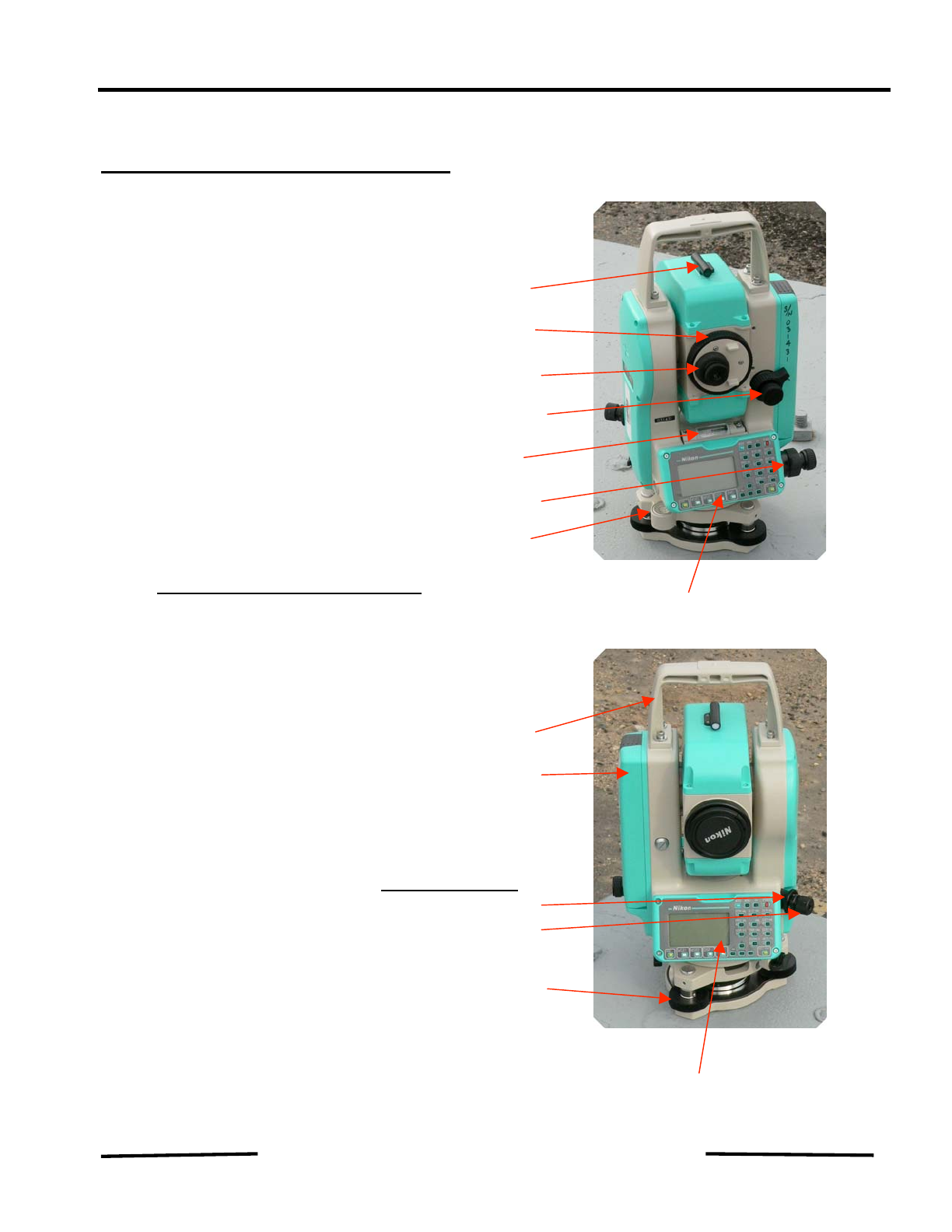
Packing Up the Nikon NPL-352
1. Adjust the level screws and the tangent screws to the neutral position.
2. Put the telescope in the Face 1 position.
3. Place the instrument in the box with the battery-side up.
If damp, leave the box open overnight to prevent condensation.
The instrument is not watertight with the battery removed, therefore store it with the
battery installed.
Keep the spare battery charged in the box.
It is suggested that the batteries for the NPL-352 be marked with the serial number of
the machine they are packed with to assure that batteries stay with their respective
machines. Likewise the purchase date should be marked to give an age of the
batteries for future replacement scheduling. Marking one of the batteries that comes
with the NPL-352 as the "A" battery and the other as the "B" battery makes it easier to
track that the batteries are being cycled through the charger on a regular basis.
It is a good idea to have a spare lens cap in the box in case the one that comes with
the machine gets lost. Any 52mm standard camera lens cap will work.
The container that the right angle eye piece comes in is a flimsy paperboard box. It is
suggested that a better container be acquired to store the eye piece in. The right angle
eye piece is usually not needed, but when it is, it is essential and deserves better
storage than a plastic bag in an unmarked paperboard box.
Remember the primary sources of error are:
1. The instrument or the prism was not correctly set over the station.
2. Sighting on the reference point was off.
3. Sighting on the measuring point was off.
Measurement Basics and Theodolite Use Page 9
FEMA US&R Response Sys/U.S. Army Corps of Engineers
STRUCTURES SPECIALIST SKILLS TRAINING October 2007
TST – Total Station Training
Use of Total Station as Theodolite
Theodolites are still valuable for monitoring structures. Total stations can be
used as simple theodolites. This section shows how to start up the NPL-352
and use it as a theodolite.
After leveling the instrument with the bull's-eye level, turn on the instrument.
The first screen that comes up requires that
the 0ozenith angle (vertical reference) be set.
This is done by simply tilting the telescope up
and down slightly. Current temperature and
pressure can be set at this time also.
Tilting the telescope will bring up the basic
measurement screens unless the instrument is
not leveled within the tolerance range of the
level compensators.
For classroom use we will turn off the
compensators using the left or right scroll keys.
After turning off the compensators you use the
ESC key to return to the Basic Measurement
Screens (BMS)
Measurement Basics and Theodolite Use Page 10
FEMA US&R Response Sys/U.S. Army Corps of Engineers
STRUCTURES SPECIALIST SKILLS TRAINING October 2007
TST – Total Station Training
There are four BMS screens which are viewed
in order by pressing the DSP key repeatedly.
When the NPL-352 is used as a theodolite, only
the first screen is needed.
After leveling the instrument with the bull's-eye level, turning it on, and before
tilting the telescope, the instrument may need to be fine leveled using the
electronic angle compensators. Fine leveling is done using the three leveling
screws under the leveling base. Again, return to the BMS screen by using the
ESC key and tilt the telescope to establish the zero zenith (vertical) angle.
Monitoring points with the theodolite is done by
sighting on a point to be monitored and
recording the horizontal angle (HA) and the
vertical angle (VA). Several points can be
monitored from a single location this way. As
long as the instrument is not moved, this can
be an adequate method of monitoring a structure. If the instrument must be
removed from its location, it must be reset exactly in its horizontal and vertical
location or the previous monitoring data cannot be repeated.
Measurement Basics and Theodolite Use Page 11
FEMA US&R Response Sys/U.S. Army Corps of Engineers
STRUCTURES SPECIALIST SKILLS TRAINING October 2007
TST – Total Station Training
It is necessary to establish a reference point to
set as the position of the zero horizontal angle.
This is commonly referred to as the Backsight
(BS) although the BS may be, and often is,
located forward of the instrument location.
The horizontal angle is set to zero through the
Angle menu which is accessed by pressing the
ANG key. Scroll to the 0-Set option and press
the REC/ENT key or press the 1key. This will
set the current orientation of the telescope as
the zero horizontal angle.
Points to be monitored are sighted and their HA
and VA recorded on monitoring forms or field
books. Field books with waterproof paper are
recommended.
Once the HA and VA are known, the points can be monitored by turning the
telescope back to their last recorded location using the tangent screws of the
instrument until the output screen of the instrument has the desired readings.
After returning the instrument to the prior recorded HA and VA settings, the
object is sighted through the telescope and movement can be immediately
ascertained by seeing if the crosshairs of the telescope are still centered on the
point being monitored. It should be noted that the accuracy of a 5 second
theodolite or total station is approximately 1/8" for a point 400 feet distant.
Although the NPL-352 is rated as a 5 second machine, its performance is
always better than this. This level of accuracy should be more than sufficient
for the purposes of monitoring points in the US&R environment.
Measurement Basics and Theodolite Use Page 12

Other Nikon Measuring Instrument manuals

Nikon PROSTAFF 3i User manual

Nikon

Nikon PROSTAFF 3i User manual

Nikon COOLSHOT 20i GII User manual

Nikon

Nikon COOLSHOT 20i GII User manual

Nikon COOLSHOT 20 GII User manual

Nikon

Nikon COOLSHOT 20 GII User manual

Nikon 8431 - Monarch - Dot User manual

Nikon

Nikon 8431 - Monarch - Dot User manual

Nikon Laser 550 User manual

Nikon

Nikon Laser 550 User manual

Nikon PROSTAFF 1000 User manual

Nikon

Nikon PROSTAFF 1000 User manual

Nikon NPL-322 User manual

Nikon

Nikon NPL-322 User manual

Nikon Callaway XHOT User manual

Nikon

Nikon Callaway XHOT User manual

Nikon MONARCH 2000 User manual

Nikon

Nikon MONARCH 2000 User manual

Nikon Callaway LR550 User manual

Nikon

Nikon Callaway LR550 User manual

Nikon Laser 550 User manual

Nikon

Nikon Laser 550 User manual

Nikon XF Series User manual

Nikon

Nikon XF Series User manual

Nikon COOLSHOT 20 GII User manual

Nikon

Nikon COOLSHOT 20 GII User manual

Nikon XF SERIES User manual

Nikon

Nikon XF SERIES User manual

Nikon 7487 - Team Realtree Laser 1200 Rangefinder User manual

Nikon

Nikon 7487 - Team Realtree Laser 1200 Rangefinder User manual

Nikon COOLSHOT LITE User manual

Nikon

Nikon COOLSHOT LITE User manual

Nikon LASER 30 User manual

Nikon

Nikon LASER 30 User manual

Nikon Forestry Pro II User manual

Nikon

Nikon Forestry Pro II User manual

Nikon COOLSHOT User manual

Nikon

Nikon COOLSHOT User manual

Nikon DTM-502 Series User manual

Nikon

Nikon DTM-502 Series User manual

Nikon Forestry Pro User manual

Nikon

Nikon Forestry Pro User manual

Nikon Monarch 7iVR User manual

Nikon

Nikon Monarch 7iVR User manual

Nikon MONARCH 2000 User manual

Nikon

Nikon MONARCH 2000 User manual

Nikon NR-5500 Operating instructions

Nikon

Nikon NR-5500 Operating instructions

Popular Measuring Instrument manuals by other brands

Castle group dBAir operating manual

Castle group

Castle group dBAir operating manual

Keller CellaTemp PA 4 Series quick guide

Keller

Keller CellaTemp PA 4 Series quick guide

BD PhoenixSpec user guide

BD

BD PhoenixSpec user guide

Hioki PW3365-20 Measurement guide

Hioki

Hioki PW3365-20 Measurement guide

ATAGO PAL-27S instruction manual

ATAGO

ATAGO PAL-27S instruction manual

Dwyer Instruments PUX2 instruction manual

Dwyer Instruments

Dwyer Instruments PUX2 instruction manual

Lovibond Photometer-System MD100 instruction manual

Lovibond

Lovibond Photometer-System MD100 instruction manual

AND AD-4401A instruction manual

AND

AND AD-4401A instruction manual

DPS Telecom NetGuardian SUI user manual

DPS Telecom

DPS Telecom NetGuardian SUI user manual

Ahlborn ALMEMO 2290-2/3 operating instructions

Ahlborn

Ahlborn ALMEMO 2290-2/3 operating instructions

Agilent Technologies U1211A User's guide and service guide

Agilent Technologies

Agilent Technologies U1211A User's guide and service guide

Toolworld 89032 quick start guide

Toolworld

Toolworld 89032 quick start guide

Eastron SDM630MCT-LoRaWAN user manual

Eastron

Eastron SDM630MCT-LoRaWAN user manual

MSA PrimaX I operating manual

MSA

MSA PrimaX I operating manual

Emerson Rosemount  MLT 2 Upgrade manual

Emerson

Emerson Rosemount MLT 2 Upgrade manual

horiba LAQUA WQ-300 Series quick guide

horiba

horiba LAQUA WQ-300 Series quick guide

Bosch GTC600C Operating/safety instructions

Bosch

Bosch GTC600C Operating/safety instructions

Rohde & Schwarz VOR/ILS Analyzer EVS200 user manual

Rohde & Schwarz

Rohde & Schwarz VOR/ILS Analyzer EVS200 user manual

manuals.online logo
manuals.online logoBrands
  • About & Mission
  • Contact us
  • Privacy Policy
  • Terms and Conditions

Copyright 2025 Manuals.Online. All Rights Reserved.