Pond Pro CAN-AIR SS User manual

CAN-AIR SS
AERATION SYSTEM
Owners Manual
18554147663
PONDPRO.CA
CAMROSE, AB
SALESPONDPRO.CA
M
A
D
E
I
N
C
A
N
A
D
A

Unit Specifications
Installation Tools & Materials
On Land Preparation
Diffuser Installation
Aeration System Connections
Safety Instructions
02
02
03
03
04
05
06
07
08
09
09
10
Compressor Shelf Installation
Post Mount Cabinet Installation
Maintenance
Troubleshooting
Winter Operating
Startup Procedure
10 Warranty
CONTENTS
table of

02
Area Covered by 1 Can-Air SS Diffuser
Pond Depth (ft) Good Ponds \ Preventative Eutrophic \ Problematic
35' x 35'50' x 50'
100' x 100'
130' x 130'
170' x 170'
235' x 235'
70' x 70'
100' x 100'
125' x 125'
175' x 175'
5 - 8
9 - 12
13 - 15
16 - 20
20 +
SAFETY
INSTRUCTIONS
UNIT
SPECIFICATIONS
Means for disconnection must be incorporated in the fixed wiring in
accordance with local and national wiring rules.
Consult a qualified electrician for electrical installation.
Use a life jacket and a flat bottom boat for installation.
Avoid boats that could easily flip like canoes.
Do not use waders in deep ponds/lakes or ponds/lakes with drop-offs,
drastic slopes, or soft bottom material.
The product owner will assume all risks with operating the Can-Air System.
Post warning signs when legally necessary (varies by location). It is highly
recommended to post signs to avoid injury or death from falling through ice.
Use extreme caution near cold water or in extreme weather conditions
when installing.
Use caution when using the system in freezing conditions — diffusers will
cause open water and thin ice around the area.
Use caution when dealing with any electrical equipment with moving parts.

03
COMPRESSOR SHELF
INSTALLATION
Systems sold without cabinets include a shelf with a cooling fan and
cord for wall mounting your compressor.
Pond Pro highly recommends that the site service providing the system have a
human-rated Ground Fault Circuit Interrupter outlet (120V) or human-rated
Ground Fault breaker (240V) for your protection.
Contact a licensed electrician to bring 120 or 240 volt (depending on model
purchased), single phase electrical supply to the compressor location and to
install appropriate human-rated ground fault protection.
Pre-drilled holes on the shelf are 16"apart to mount on most standard studs.
Secure the shelf to studs with four screws (min. 1.5" wood screw recommended).
Mount the compressor and align the rubber feet with the holes.
Tighten feet using nuts supplied.
Systems purchased
without a cabinet are
only warranted for
2 yrs instead of 3 yrs.
NOTE:
Correct installation is your responsibility. Make sure
you have the proper installation conditions and that
installation clearances do not block airflow.
Compressor needs to be installed in a clean, dry
location and protected from dirt, moisture and weather.
Temperature readings taken 4” away from any surface
of the compressor must not exceed 104° F (40°C).
Adequate ventilation and cooling air must be provided to
keep the compressor from overheating and causing premature
damage. A fan must be used.

04
POST MOUNT
CABINET INSTALLATION
DO NOT INSTALL CABINET ON THE GROUND. CABINET MUST BE
INSTALLED AT LEAST 4' OFF THE GROUND WITH VENTS UNOBSTRUCTED.
Finish connecting tubing to the lead hose using the supplied fittings. Secure and
tighten all clamps. You may need to use insulated hose under the water freeze
mark and/or trench and bury tubing from the compressor to the pond. Plug fan
and compressor into the supplied three-pronged 6’ power cord when ready.
The post mount cabinet must be attached to a sturdy post or
to a vertical wall with electrical service. If possible, install
rubber between the post and the cabinet to reduce vibrations.
Pre-drill (2) holes that will align with those on the wall of the
cabinet already drilled. Install 1 lag screw into the wall or
post, leaving the hex head out roughly ¼".
Hang the cabinet from lag screw using the bottom key-hole
slot in the cabinet (a second person may be needed to help
hold the cabinet in place). Install the second lag screw in the
top mounting hole. Tighten the bottom lag screw.
CAUTION
COMPRESSOR DAMAGE.
Please install as shown in the following pictures, dropping the plug into the bottom
of the box through the 1 1/4” adapter. A cord protector is provided. Use this on the
outside of cord before clamping the cord to the box.

05
Connect the sinking airline to the
insulated line with a hose barb
connector. Make sure the insulated
line is long enough to end below ice
in low water conditions. The insulated
line will need weight to sink the line
(e.g. rebar, cinder block). Attach the
other end of the insulated line to the
red line from the compressor with a
hose barb connector. Split the last foot
of insulated line and cut the polyline
out. Use the last foot of insulation to
wrap the red hi-temp hose. The hi-
temp hose should extend at least 18"
from the compressor to reduce heat
to the polyline.
Run sinking airline all the way to the
compressor. It is recommended to run
the airline through a conduit to protect
from rodents chewing the line on or close
to shore. Make sure there is a minimum of
18"red hi-temp airline at the compressor
before connecting the sinking airline with
a barb and screw clamps.
Frost Zone: No Frost Zone:
For areas where it often gets below
freezing, we use the Pond Pro
insulated airline to go from
compressor to below the ice in the pond.
Compressors condensate and the
condensation can freeze.
AERATION SYSTEM
CONNECTIONS
If your aeration system set-up does not include insulated
airline, the sinking airline must be buried below the frost
line which can vary from 6 - 10 ft (region dependent).

06
ON LAND
PREPARATION
INSTALLATION
TOOLS
MATERIALS
(Optional) nylon rope (or equivalent)
with length at least twice the water depth
7/16” socket wrench
7/16” box or open end wrench
5/16” socket/nut driver
Flat-head screwdriver
2
1
3
A short 3/8” I.D. piece of sinking airline has
been pre-installed on the diffuser for you.
Attach the inside end of the 100’ roll of 3/8” I.D.
sinking airline to this short piece using a hose
clamp and the hose barb fitting provided. Tighten
using a socket/nut driver or flat head screwdriver.
Do not over tighten clamp.
4
5
If a boat is being used (preferred) for diffuser placement, tie a rope to
the outer holes on the diffuser body to allow you to drop the diffuser
down to the bottom. If no boat is available (only works for 100’ or less),
tie a rope to one of the outer diffuser holes and pull diffuser into position
with 100’ of sinking airline attached.
*If fish are present, do not install the diffuser straight to the pond
bottom. To keep the diffuser off of the bottom, tie a float to the arms
with enough buoyancy to keep the diffuser suspended.
Remove diffuser from the box and gently
pull the diffuser aeration tubing loose.
Unwrap the three stainless steel arms.
Slip the end of arm opposite the orange
clip into the notch on the diffuser base.
Ensure the orange clip is facing up.
Align the hole in base and arm. Insert
screw and tighten. Repeat this step
with the other two arms.
Press diffuser aeration tubing into the
orange plastic clip at the end of each
diffuser arm.
6

DIFFUSER
INSTALLATION
Consider where the Can-Air Diffuser(s) are to be located in the pond. Proper
diffuser placement is key for aeration efficiency. If using more than one, space
the diffusers equally from one another in a depth that embodies the majority
of the pond. Contact Pond Pro with any questions on placement.
2
Load your boat with the pre-assembled diffuser and the 100'roll of 3/8” I.D.
sinking airline already attached. If the diffuser is more than 100'from the
compressor, additional rolls of 1/2” I.D. sinking airline will be required . For
every extra roll of sinking airline, you will need one hose barb connector and
two hose clamps.
3
Position the boat near the pre-determined diffuser location. Slowly lower the
diffuser into the water. Make sure the diffuser is being lowered upright and level.
Do NOT drop the diffuser in an upside down or sideways orientation. Use the
[optional] rope to guide the diffuser, or release the diffuser at the surface and
allow it to sink to the bottom naturally. Always ensure that there is a sufficient
amount of airline to avoid strain on the connection when dropping the diffuser.
4
1
5
Once the diffuser is positioned, the [optional] rope may be kept in place and
tied to a buoy for easier locating of the diffuser in the future. Slowly unspool
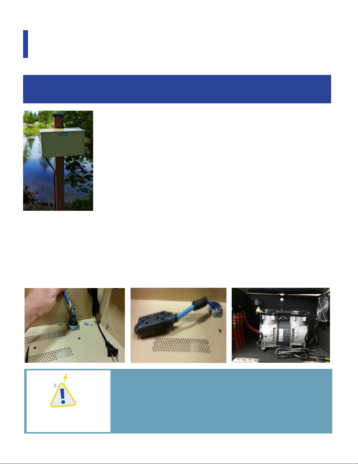
the 3/8’’ I.D. airline into the water and make your way back to the shore
where your compressor is located. Connect the airline to the compressor
manifold/barbs and secure with clamps.
WHEN FISH ARE PRESENT
Do not install the diffuser straight to the bottom. A float with
enough buoyancy to suspend the diffuser will be needed.
Install your diffuser(s) at half-depth to not disturb the
bottom and cause the anaerobic sludge to mix with the water.
Lower it by 2' every second week until it is on the bottom.
For systems with two or more diffusers, repeat steps 1-3 for every diffuser.
Once all diffusers are placed and properly connected to compressor
manifold/barbs, the diffusers are ready to be balanced (in a multi-diffuser
system set-up) or the system is ready to start up.
To balance the diffusers, turn on the compressor and visually inspect the
diffusers’ bubbling performances. In small ponds this can be done from shore.
In larger ponds/lakes, visual inspections may need to be done from the boat.
Diffusers should all have similar bubbling action. If one appears weaker, reduce
the air flow to the other diffuser(s) by adjusting the ball valve(s) on the
manifold. Once the diffusers appear equal, your system is ready to operate!
Please note: Diffusers are weighted and self-righting but proper placement
can be confirmed by checking for a rising pillar of bubbles, after connnections
and power set up are complete.
07

08
Check intake filter after the first 500 hours of operation.
Clean filter and determine how frequently filters should
be checked during future operations.
Filters should be checked monthly and replaced as needed.
To Replace Filter:
Remove filter cover
Remove felt and replace filter element
MAINTENANCE
With adequate maintenance your Can-Air
Aeration System can operate trouble-free for years!
Air Filters
Compressors should be rebuilt every 18-24 months.
The compressors are oil-less and require NO lubrication.
Compressors
Diffusers should be rebuilt every 5-7 years.
Diffusers
Pond Pro readily stocks rebuild kits for all compressors used
in Can-Air Aeration Systems.
Pond Pro readily stocks Can-Air diffuser rebuild kits.
Rebuild Kits & Replacement Filters/Parts can be
ordered online at www.pondpro.ca or picked up from
our store. Call us at 1-855-414-7663 with any questions
or to contact us about warranty claims.
WARNING:
WARNING:

09
TROUBLESHOOTING
Here are some helpful troubleshooting tips.
If a problem occurs, please double check the
assembly and installation instructions.
Contact Pond Pro if problems persist
after reviewing these instructions.
“Compressor and fan are not running.”
Check to make sure the power cord is connected.
Check if the user supplied GFCI circuit is tripped and
if it is, push the reset button.
“The fan is running but the compressor is not”
Check the compressor and capacitor wiring. If no damage
is seen, a bad capacitor or compressor may be the issue.
“The compressor stops and restarts”
This is likely a heat issue. Ensure the fan is working properly.
“The compressor and fan are running, but there
are no bubbles coming out of the diffuser(s)”
Check for any leaks in the line connections and in the
cabinet. Re-tighten any loose connections. The compressor
air filter may need to be cleaned or replaced.
“The compressor and fan are running. There are
bubbles coming out of some diffusers, but not all.”
The valves in the cabinet may need to be balanced correctly.
There may be a clog on a diffuser that needs to be removed.
The compressor may be faulty and need a rebuild kit.
Using closed cell polyurethane foam to insulate your airlines will prevent ice
build-up in the lines which can occur due to condensation. Ice buildup in the line
can block the flow of air to your diffuser and can cause damage to your compressor.
If your body of water fluctuates greatly, run the insulation further in the water
to account for low water level. You want the airline to be insulated through
any ice thickness and into an area of water that will be below the ice level.
If only desiring to keep a small area open to prevent winterkill, it is
recommended to move the diffusers closer to shore to allow shoreline
to be in direct contact with the ice-free opening.
WINTER
OPERATING
In climates where temperatures are
likely to fall below freezing, it is
recommended that you insulate the
airlines from the compressor cabinet
to a minimum of three feet into the water.

10
Some water bodies have a warmer (less
dense) top layer and a colder (more dense)
bottom layer. Can-Air Systems are designed
in a way that allows these natural thermal
stratification processes to keep occurring.
However, extremely stratified water bodies
require special attention.
To test for extreme stratification, reel a
thermometer into the water and pause every
couple feet to pick up a reading.
Pull the thermometer quickly to the surface
to record each reading. If over 30% of the
total water volume is cold water (-15 C°
below surface water temperatures),
caution must be taken when turning on
the aeration unit. Only run in short time
intervals. Start cautiously (e.g. one hour/day
for the first week) and gradually increase
running time throughout the following
weeks. Units can be run longer during
sunny days when photosynthesis is
supplementing oxygen levels.
Why is this important? Stirring up cold
bottom water can expose fish to potentially
harmful gases. Rapid mixing can also
decrease overall oxygen levels in ponds with
anoxic bottom conditions.
If you are at all concerned about this
process please contact Pond Pro by calling
1-855-414-7663 or emailing
Warranty period is three years with the cabinet and
two years without the cabinet.
Pond Pro warrants this Can-Air System to be free
from defects in material or workmanship under
normal use and service. The obligation of Pond Pro
under this warranty is limited to replacing or
repairing any defective part within the warranty
period free of charge. The customer is responsible
for paying all shipping charges associated with
returning the unit to Pond Pro repair facility.
THIS WARRANTY IS IN LIEU OF ANY OTHER
WARRANTIES, EXPRESSED OR IMPLIED, AND ANY
OTHER OBLIGATION OR LIABILITY WHATEVER ON
THE PART OF POND PRO. AND IN NO EVENT POND
PRO WILL BE LIABLE FOR ANY SPECIAL OR CON-
SEQUENTIAL DAMAGES.
Warranty is void if:
The system is incorrectly installed, not maintained
under the maintenance guidelines contained in this
manual or the system has been tampered with.
Warranty Claim Procedure:
Once warranty coverage has been established,
please call Pond Pro at 1-855-414-7663 prior to
returning the unit to receive any updated informa-
tion and fill out a repair form. The repair form
should be sent with information explaining the
problem and a copy of the original invoice. The
unit can be sent to any Pond Pro repair centre for
evaluation and repair. Any expedited shipping
method for the return of the unit is at the expense
of the customer.
Non-Warranty Repairs:
Most failed equipment is cheaper to repair than to
replace. Please call ahead and ship as directed in the
previous section.
Customers may request an estimate of repair. This
can be sent in the letter that accompanies the unit,
and should include a daytime phone number and/or
email address. Once the unit has been received at
the repair centre and evaluated, the customer will be
contacted as to whether to proceed with the repair.
The unit will be repaired if repair costs are below the
stated dollar amount. For example: “Please repair if
total is under $150.00 before shipping charges.”
Estimates that are rejected will be destroyed unless
the customer has stated otherwise. If the customer
requests their unit be returned, it will be returned as
closely as possible to the state it was received.
Shipping and handling charges will be covered by
the customer.
All non-warranty repairs will be returned to the
customer and billed C.O.D. unless otherwise directed.
Check local laws and ordinances as warning
signage is mandatory in some areas. The
owner of the Can-Air system will assume all
risks of running the system during the
winter months.
Winter operation may result in open areas
and thin ice at the diffuser location(s). Use
extreme caution to avoid falling through ice
in these areas. To prevent injuries or fatali-
ties, warning signs are highly recommended.
In the spring, refer to the start up procedure
above to prevent fish kills.

North America’s Pond Superstore
Table of contents
Other Pond Pro Lawn And Garden Equipment manuals

Pond Pro
Pond Pro CAN-AIR BLUE User manual

Pond Pro
Pond Pro CAN-AIR ECO User manual

Pond Pro
Pond Pro CAN-AIR BLUE DIFFUSER User manual

Pond Pro
Pond Pro CAN-AIR KOI 1 User manual

Pond Pro
Pond Pro CAN-AIR KOI 4 User manual

Pond Pro
Pond Pro CAN-AIR MEGA User manual

Pond Pro
Pond Pro CAN-AIR SS DIFFUSER User manual

Pond Pro
Pond Pro CAN-AIR KOI 1 PLUS User manual

Pond Pro
Pond Pro CAN-AIR KOI 3 PLUS User manual

Pond Pro
Pond Pro CAN-AIR KOI 2 User manual