Pool Pro MINERALX Troubleshooting guide


CONTENTS
1. Important Warnings/Safety Instructions .......................................................... 3 - 4
2. Packaging Contents ............................................................................................ 4
3. Tools Needed ...................................................................................................... 4
4. Preparing the Pool ............................................................................................... 5
5. Recommended Water Balancing ......................................................................... 6
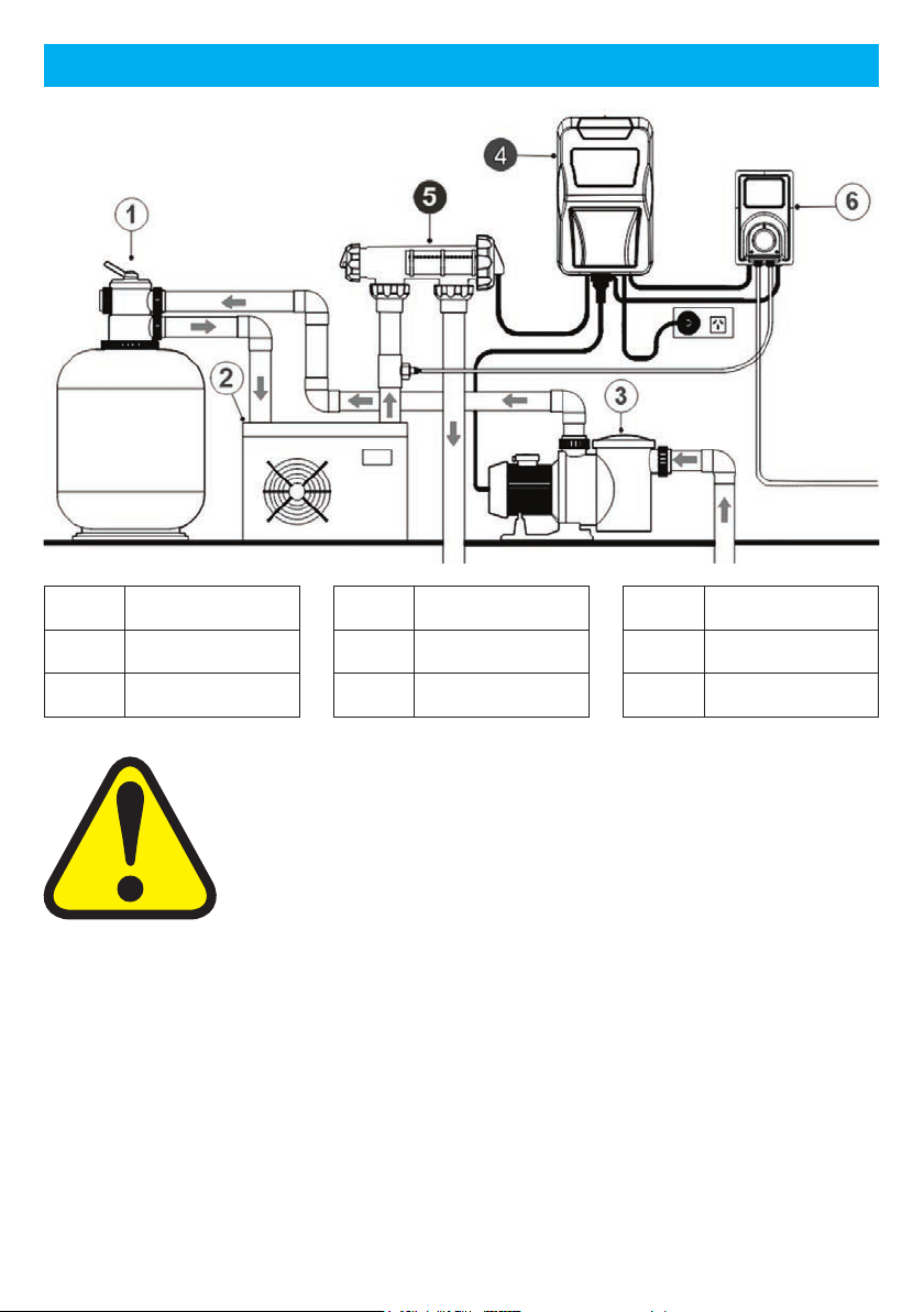
6. Installation Diagram ........................................................................................ 7 - 8
7. Installing the Chlorinator Power Pack ................................................................. 8
8. Installing the Cell ................................................................................................. 8
9. Control Panel Operation ...................................................................................... 9
10. Initial Start-up .................................................................................................... 10
11. The Main Screen ............................................................................................... 11
12. Shortcut Buttons ................................................................................................ 11
12.1 Shortcut Button: Power/Mode ................................................................ 11
12.2 Shortcut Button: Chlor Boost ........................................................... 11 - 12
12.3 Shortcut Button: Winter/Blanket ............................................................. 12
12.4 Shortcut Button: Clock/Timer ........................................................... 12 - 13
12.5 Shortcut Button: Salt Test ................................................................ 13 - 14
12.6 Shortcut Button: Backwash ............................................................. 14 - 15
13. Main Menu ......................................................................................................... 15
13.1 Main Menu: Backwash ........................................................................... 15
13.2 Main Menu: Brightness ........................................................................... 15
13.3 Main Menu: Cell Cleaning ...................................................................... 15
13.4 Main Menu: Chlor Boost ......................................................................... 16
13.5 Main Menu: Chlor Setting ....................................................................... 16
13.6 Main Menu: Clock/Timer ......................................................................... 16
13.7 Main Menu: Contrast .............................................................................. 16
13.8 Main Menu: Power/Mode ....................................................................... 16
13.9 Main Menu: Pump Setting ...................................................................... 16
13.10 Main Menu: Salt Test .............................................................................. 17
13.11 Main Menu: Service Menu ...................................................................... 17
13.12 Main Menu: Spa Mode ........................................................................... 17
13.13 Main Menu: Winter/Blanket .................................................................... 17
13.14 Main Menu: pH Control Mode ......................................................... 17 - 18
14. Chlorinator Maintenance ................................................................................... 19
15. Troubleshooting .......................................................................................... 20 - 22
16. Schematics ................................................................................................. 23 - 25
17. ChlorineProductionandSpecications............................................................. 25
18. Technical Support .............................................................................................. 26
19. Warranty ..................................................................................................... 26 - 27
20. Product Registration .......................................................................................... 27
Section Page #

Page 3www.poolpro.com.au
This manual contains important information about the installation,
operation, and safe use of this product. This information should
be given to the owner and/or operator of this equipment. When
installing and using this electrical equipment, basic safety
precautions should always be followed. Failure to follow safety
warnings and instructions in this manual can result in serious injury
and/or damage to your equipment. Read and follow all warning
notices and instructions which are included in this manual.
●The Power Supply internally contains live components. There is a danger of electric
shock if opened. If the power cord is damaged then it should be replaced by the
manufacturer, their agent or similar.
●To reduce the risk of injury, do not permit young children to use this product
unless they have been trained by the person responsible for their safety and they
acknowledge their ability to use such equipment. To reduce the risk of accidents
or incidents, service on the unit should only be performed by your local pool
Professional.
●When mixing acid with water, ALWAYS ADDACID TO WATER. NEVER ADD
WATER TO ACID.
●DO NOT PLUG UNIT IN IF CARTON HAS BEEN WET.
●GAS BUILDUP CAN OCCUR WITH IMPROPER WIRING: To reduce the risk of
1. IMPORTANT WARNINGS/SAFETY INSTRUCTIONS
Congratulations on your recent purchase of your Pool Pro MineralX Chlorinator.
Please take a moment to read through the entire manual before installing your new
unit.Yourchlorinatormustbeinstalledandoperatedasspecied.
Whileeveryeorthasbeenmadetoensurethattheinformationcontainedinthisguide
is accurate and complete, no liability can be accepted for any errors or omissions.
PoolProreservestherighttochangethespecicationsofthehardwareandsoftware
described herein at any time without prior notice.
Please remember that your Pool Pro MineralX Chlorinator is not designed to chemically
maintain your pool water and keep it balanced, but rather to produce chlorine from a
mild salt solution within the water. We encourage regular water testing, balancing and
correction if, and when required to maintain the recommended balanced levels of your
pool water. This is a vital part of a complete maintenance program and will ensure
trouble free performance as well as a healthy and sparkling clean pool.
The Pool Pro MineralX Chlorinator models (NDCMX25 and NDCMX35) are reverse
polarity units designed to automatically change direction every 4-16 hours (depending
on your setting). This change of polarity causes the calcium to dislodge and keep the
cell plates clean. Occasional cleaning of the electrode plates may still be necessary.
Thank you again for choosing a Pool Pro MineralX Chlorinator. We wish you many
happy years of swimming in your crystal-clear pool.

Page 4 www.poolpro.com.au
personal injury the Power Pack is designed so that the Electrolytic Cell will only
receive power when the pool pump is on. Otherwise, dangerous chlorine gas
build-up can occur. If the pump is not installed to the AC Socket (pump outlet) on
the Power Pack, then the installer must ensure that the Electrolytic Cell is never
energizedwhenthepoolpumpisOFF,orwaterisnotowingthroughtheunit.
●Read and keep your user manual in a safe place.
●Increase chlorine production when temperature goes up.
●Use Stabiliser to stabilise chlorine in the swimming pool.
●For Pool Pro MineralX Chlorinator models NDCMX25 and NDCMX35, maintain
your salt level at 1500ppm for optimum performance.
●Decrease production when temperature goes down - see Section 12.3 WINTER/
BLANKET MODE.
●Disclaimer: Information in this guide is intended to provide general information
on a particular subject(s) in good faith and is not an exhaustive treatment of such
subject(s). Its use is beyond the control of the author, contributor, publishers,
and distributors and should not be relied upon without consulting your local
Professional for comprehensive advice. This guide includes subject(s) that should
only be performed by or under the direction and advice of your local Professional
and under no circumstances should the guide be used as a substitute for such
professionals. No representations or warranties are made that the content, advice,
and recommendations in this guide are current, free from errors or omissions, or
appropriate for the user’s circumstances or abilities. No liability is accepted for any
losssueredasaresultofanyuser’srelianceonsuchcontent.
2. PACKAGING CONTENTS
Wall
mounting
bracket
Power
pack Cell housing with
unions
2 x 50/40
reducing
bushes
2 x green
wall plugs
with screws
User
manual
3. TOOLS NEEDED
Drill with
6mm drill bit Basic PVC
ttings Hacksaw
PVC primer &
PVC cement
“Type P” for
pressure pipes
No.2
Phillips head
screwdriver

Page 5www.poolpro.com.au
4. PREPARING THE POOL
Check your salt levels in your pool before starting your unit. See Section 12.5 to
perform a SALT TEST.
Salt levels and mineral levels should be 1200ppm – 1800ppm (ideally 1500ppm) for
NDCMX25 and NDCMX35 models, and no more than 2500ppm. To achieve this TDS
with minerals, you may need to add 20-30% more product to the pool water. Contact
your local pool Professional for further assistance.
Salt levels above 2500ppm on these models may overload the unit and cause
excessive heat and void your warranty.
For all new pool installations please seek advice from your pool builder or your local
pool Professional before adding salt, as some new surfaces request no salt to be
added when initially completed.
NEVER ADD SALT/MINERALS DIRECTLY TO THE SKIMMER BOX. This high
concentration of either salt or minerals will pass through your filtration, pump
and other pool equipment. Remove automatic pool cleaner from the pool before
adding salt or other chemicals.
HANDY TIPS:
The colder the water the lower your output, but this does not mean you need more salt.
There will always be less chlorine demand in colder water.
For salt only: We recommend adding 1.5kg of pool salt per 1000 litres of pool water
for the Pool Pro MineralX Chlorinator.
For minerals/magnesium chloride: Allow an extra 20-30% of the product to achieve
the correct TDS for these types of salts. Follow the instructions on the product
packaging and/or consult your local pool Professional.
Salt and minerals should always be added to the shallow end of the pool and allowed
todissolve.Donotletthesalt/mineralssettleontheoorofthepoolasitmaycause
damage to the surface. Use your pool brush to mix the salt/minerals into the water.
Running the pump will mix the water and help the salt/minerals to dissolve.
Onlyrunthepumpintherst8-12hours(ensurethecellisswitchedo)toallowthe
salt/minerals to dissolve.
By pressing [SALT TEST] a salt measurement is taken, and a total TDS reading is
displayed. The ideal TDS reading should be an LCD display of “OK”, approximately
1200ppm – 1800ppm. If “HIGH” is displayed, the salt level is above 2500ppm and
the salt level is too high, and if “LOW” is displayed the salt is below 1200ppm and we
suggest taking a sample to your local pool Professional for a more accurate result and
further assistance.

Page 6 www.poolpro.com.au
5. RECOMMENDED WATER BALANCING
Consult your local Pool Pro Professional to correctly balance your pool water. Follow
instructions on the packaging of each chemical. Always add chemicals to water, never
add water to chemicals.
Recommended Values for
Pool Pro MineralX Chlorinator To Increase Value To Decrease Value Test
Frequency
pH Concrete: 7.2 – 7.6 Fibreglass/
Vinyl: 7.0 – 7.2 Add Pool Pro pH
Increaser (Soda Ash) Add Pool Pro
Hydrochloric Acid Weekly
Free
Chlorine 1 – 3ppm Increase the chlorine
output on the chlorinator
unit
Add Pool Pro Chlorine
Out and decrease the
chlorine output on the
chlorinator unit
Weekly
T.A. (Total
Alkalinity) Concrete: 80 – 150ppm
Fibreglass/Vinyl: 80 – 120ppm AddPoolPropHBuer Add Pool Pro
Hydrochloric Acid Fortnightly
Calcium
Hardness Concrete: 250 – 300ppm
Fibreglass/Vinyl: 150 – 200ppm Add Pool Pro Hardness
Raiser Add Pool Pro Calcium
Remover Fortnightly
Stabiliser 30 – 60ppm Add Pool Pro Stabiliser or
Pool Pro Rapid Stabiliser
Contact your Pool
Pro Professional for
advice Fortnightly
Salt 1200 – 1800ppm
(1500ppm ideal) Add Pool Pro MineralX or
PoolProUltraneSalt
Partially empty the
poolandrellit Fortnightly
Thisisaguideonly,doesnotconstituteandshouldnotbeusedasanalternativetospecicprofessional
advice. Pool Pro and The POPS Group Pty Ltd accept no liability for any damage, loss or harm associated
with the use of this guide.

Page 7www.poolpro.com.au
6. INSTALLATION DIAGRAM
Ref # Item
1 Pool Filter
2 Heat Pump
Ref # Item
5 Cell Housing
6 pH Controller
IMPORTANT NOTES
The pump rating must not exceed 8amps.
Saltwater may damage electrical components in the Power Pack.
WARNING: We DO NOT recommend the use of valves on the
inlet or outlet of the cell housing. If you do use a valve, then it is
important to ensure that the valve cannot deadhead (lock closed)
whilethepumpisrunning.Itistheinstaller’sresponsibilitytoensuresomeformofow
control is installed in this instance and it disables the pump.
ALWAYS ensure that pipe work and equipment do not allow gases generated from the
Cell to collect and build up in any part of the installation.
It is RECOMMENDED that the Cell Housing be installed horizontally to create a
natural gas trap that acts as a safety device. Installation in any other way may cause
explosion, injury or death if the installer does not allow for gas removal. A venturi pipe is
installed/molded within the Cell Housing design to eliminate any possible gas build up,
although it is always recommended to ensure proper installation to eliminate this from
happening.
Ref # Item
3 Pool Pump
4 Chlorinator

Page 8 www.poolpro.com.au
8. INSTALLING THE CELL
Connect the Cell Housing horizontally in the return line to the pool (use reducing
bushes supplied if 40mm PVC pipe) using high pressure PVC glue. The Cell Housing
can be mounted vertically but provision must be made for a gas trap.
DirectionofwaterowthroughtheCellHousingisnotcriticalalthoughwedo
recommend entry from the closed end of the Cell Housing and exit from the end closest
to the Cell Locking Ring. The reason is to cause less water hammer over time on the
cell plates.
Check that the O-Ring is clean, greased with silicone grease (DO NOT use petroleum-
based jelly) and securely located in the Cell Housing.
EnsureCellLockingRingisrmlytightenedbyhand(DONOTusedatooltotighten).
Connect the lead from the Cell Electrode to the Cell Plug under the Power Pack
ensuringarmsnaplockconnection.
Plug the Power Pack’s 3 pin plug into a suitable weatherproof RCD protected 10amp
outlet and then plug the pump into the 3 pin AC Socket located at the bottom of the
Power Pack.
7. INSTALLING THE CHLORINATOR POWER PACK
The Pool Pro MineralX Chlorinator has an Ingress Protection Rating of IP23 enabling
it to be installed outdoors. Regulations require that the Power Pack shall be installed
outside the pool zone. The Power Pack shall be installed according toAS/NZS 3000
wiring rules.
The Power Pack should be installed in a well-ventilated position ideally away from
sunlightandraintoprolonglifeandatleast1mabovegroundtopreventrunowater
entry.
Ensure that the Power Pack is not stored near chemicals, fertilisers or in a closed
unventilated shed with similar products as the fumes will cause excessive corrosion
and damage to the internals of the Power Pack and may void warranty.
WhenmountingthePowerPackonapostitisrecommendedtoinstallaatpanelat
least the same size to act as a waterproof backing plate.
Mount the Power Pack with the Mounting Bracket, Green Plugs and Screws provided.
The Power Pack should be mounted no further than 1.5m from the Chlorinator Cell for
ease of operation.
The Cell Housing must be installed in the RETURN pipework to the pool. It must always
beinstalledafterthelter,gasheater,solarheating,orheatpump.
DONOTapplypriminguidtotheCellHousing,itisnotneededandmayreactwiththe
plastic.

Page 9www.poolpro.com.au
9. CONTROL PANEL OPERATION
BUTTON FUNCTION
Sets the chlorinator’s operating mode between AUTO, ON and OFF.
This is displayed on the LCD screen next to “Mode”.
Sets the chlorinator and pump to operate for 8 hours at 100% output.
Defaultsto8hoursbutcanbemodied.
Reducesthechlorineoutputto50%.Defaultsto50%butcanbemodied.
Sets the clock (time of day) and the timer (chlorinator operating times).
Measures the salt level of the pool water. Also shows the salt value.
Runsabackwashprocesstocleanthemediainsidethepoolltersystem.
- Enters the Main Menu if pressed when the LCD screen is displaying the
Main Screen (see Section 11 on page 11).
- Saves any changes made to the settings.
- Scrolls up any menus.
- Adjusts values of any options selected.
- Scrolls down any menus.
- Adjusts values of any options selected.
- Exits menus.
- Returns to the previous screen.
UsedduringservicebyqualiedPoolProProfessionals.
IMPORTANT NOTES
After 60 seconds of inactivity in any
display, the display will return to the
Main Screen.
After 10 minutes of inactivity in any
display, the LCD screen will dim.
Simply press any button on the
control panel to wake the screen.

Page 10 www.poolpro.com.au
On initial startup of your Pool Pro MineralX Chlorinator the screen will run through a
start-up sequence. Please wait until “START UP CLOCK SET” is displayed.
SETTING THE CLOCK (time of day)
1. “START UP CLOCK SET” will display on the LCD screen.
2. “00”willashforHours.Press or to change the hour. Press to save.
3. “00”willashforMinutes.Press or to change the minutes. Press to
save.
SETTING THE TIMER / RUN PERIOD (daily run times of the chlorinator)
1. “START UP RUN PERIODS” will display on the LCD screen. “2 CYCLES/DAY” will
ash.
2. Press or to scroll through the cycles.
Select from the following cycles for your chlorinator to operate:
(a) “2 CYCLES/DAY” = 6am - 10am and 4pm - 8pm
(b) “1 CYCLE AM” = 8am - 4pm
(c) “1 CYCLE PM” = 8pm - 4am
3. Press to save or press to exit without saving. If these cycle times are not
suitable, you can change them in the Clock/Timer function – see Section 12.4 on
pages 12-13.
SETTING UP THE POOL SIZE
1. “START UP INFORMATION” will display on the LCD screen. The litre quantity for
“POOLSIZE”willash.
2. Press or to change the litre quantity by 1,000L increments, hold or
to change the litre quantity by 5,000L increments.
3. Press to save or press to exit without saving.
SETTING UP THE MINERAL TYPE (if your pool uses salt or mineral mix)
1. “STARTUPINFORMATION”willdisplayontheLCDscreen.“SALT”willash.
2. Press or to change the type of mineral used in the pool water. Select from
“SALT” or “MINERAL”.
3. Press to save or press to exit without saving.
10. INITIAL START-UP

Page 11www.poolpro.com.au
The Main Screen displays the current
settings for the chlorinator.
Output = The output percentage.
(●) symbol = Normal operation.
T1 or T2 = “Single Timer Cycle” or “Dual
Timer Cycle” is selected.
Mode = ON, OFF or AUTO.
HH:MM = The time of day in 24 hour format.
Cell = Cell status (FWD, REV or OFF).
Pump = The status of the pool pumpAC socket (ON or OFF).
Water Temp = Pool water’s temperature.
11. THE MAIN SCREEN
12.1 SHORTCUT BUTTON: POWER/MODE
This function changes the operating mode of the chlorinator. AUTO = running on the
timer settings. ON = manually running, not using the timer settings. OFF = not running
manually or on the timer settings.
1. Press the button to change between AUTO, ON and OFF.
2. The mode can also be accessed via the main menu. Press the button to enter
the Main Menu. Press or to scroll through the menu. Press to select
Power/Mode.
3. Press or to adjust the power/mode.
4. Press to save or press to exit without saving.
12.2 SHORTCUT BUTTON: CHLOR BOOST
This function sets the chlorinator and pump to operate for 8 hours at 100% output,
known as Chlor Boost or Superchlorination (extra sanitising time).
1. Press the shortcut button or enter Chlor Boost via the Main Menu.
12. SHORTCUT BUTTONS
Some of the menu items have shortcut buttons on the
touchpad, allowing quick access without going through
the main menu. The shortcut buttons are:
POWER/MODE CLOCK/TIMER
CHLOR BOOST SALT TEST
WINTER/BLANKET BACK WASH
NOTE: You must be on the Main Screen for the
shortcut buttons to function.

Page 12 www.poolpro.com.au
12.3 SHORTCUT BUTTON: WINTER/BLANKET
Thisfunctionreducesthechlorineoutputto50%(defaultsto50%butcanbemodied)
when the unit is either in AUTO or ON mode.
1. Press the shortcut button or enter Winter Mode via the Main Menu.
2. Press or to adjust the output percentage.
3. Press to save or press to exit without saving.
4. “Mode: Winter” and the new chlorine output will display on the Main Screen.
5. Press the shortcutbuttontoturnWinterModeoandreturnto100%output.
12.4 SHORTCUT BUTTON: CLOCK/TIMER
This function changes the time of day (clock) and the chlorinator run times (timer).
CLOCK SETTINGS (time of the day):
1. Press the shortcut button or enter Clock/Timer via the Main Menu.
2. Press the shortcut button again. “CLOCK SETTING” will be displayed on the
LCD screen.
3. Thehourswillash.Press or to adjust the hour. Press to save.
4. Theminuteswillash.Press or to adjust the minutes.
5. Press to save or press to go back to the hours. Press again to exit
without saving.
TIMER SETTINGS (when the chlorinator will run):
Selectatimercycleandthenprogramthetimesforthecycle/s.Formaximumeciency
set the cycle times to run early morning and evening. To run the chlorinator in the “ON”
power mode and override the internal timers, leave all timer settings as 00:00.
Ideal Summer settings: 6am - 10am and 4pm - 10pm (less hours for small pools,
more hours for extreme weather). Ideal Winter settings: See Section 12.3 on page 12.
1. Press the shortcut button or enter Clock/Timer via the Main Menu.
2. The cycle will automatically begin and run for 8 hours by default.
3. Press or to adjust the run time. You cannot use any other functions while
the Chlor Boost function is running.
4. Press to stop the cycle if needed, otherwise the chlorinator will revert back to
normalsettingsoncethecyclehasnished.

Page 13www.poolpro.com.au
2. Press to change between SINGLE CYCLE (chlorinator runs once per day) or
DUAL CYCLE (chlorinator runs twice per day).
3. Press to save the timer cycle and enter the timer program.
4. To set the ON/START time for TIMER 1:
“TIMER1:ONTIME”willdisplayontheLCDscreen.Thehourswillashonthe
LCD screen. Press or to adjust the hour. Press to save. The minutes
willash.Press or to adjust the minutes. Press to save and continue to
Step 5, or press to go back to the hours and repeat Step 4. Press again to
exit without saving.
5. To set the OFF/STOP time for TIMER 1:
“TIMER1:OFFTIME”willdisplayontheLCDscreen.Thehourswillashonthe
LCD screen. Press or to adjust the hour. Press to save. The minutes
willash.Press or to adjust the minutes. Press to save and continue to
Step 6, or press to go back to the hours and repeat Step 5. Press again to
exit without saving.
6. If you chose SINGLE CYCLE, you will be taken back to the Main Screen.
If you chose DUAL CYCLE, continue to the next step.
7. To set the ON/START time for TIMER 2:
“TIMER2:ONTIME”willdisplayontheLCDscreen.Thehourswillashonthe
LCD screen. Press or to adjust the hour. Press to save. The minutes
willash.Press or to adjust the minutes. Press to save and continue to
Step 8, or press to go back to the hours and repeat Step 7. Press again to
exit without saving.
8. To set the OFF/STOP time for TIMER 2:
“TIMER2:OFFTIME”willdisplayontheLCDscreen.Thehourswillashonthe
LCD screen. Press or to adjust the hour. Press to save. The minutes
willash.Press or to adjust the minutes. Press to save and return to
the Main Screen or press to go back to the hours and repeat Step 8. Press
again to exit without saving.
12.5 SHORTCUT BUTTON: SALT TEST
This function measures the salt level in the pool water. This function is a guide only.
Have your pool water tested by your local Pool Pro Professional in order to add correct

Page 14 www.poolpro.com.au
12.6 SHORTCUT BUTTON: BACKWASH
Thisfunctionassistsyouintheoperationofyourpumpandlterduringthebackwash
process.
IMPORTANT: Never operate the filter’s multi-port valve lever while the pump is
running, as it may cause damage and leaking. The pump will start and stop as
you require. Ensure all valves, valve handles, lids, baskets etc are in the correct
positions as per the requirements of the manufacturer of the equipment.
1. Press the shortcut button or enter Backwash via the Main Menu. The LCD
screen will display “BACKWASH MODE”.
2. Rotatethelter’smulti-portvalvelevertothe‘Backwash’positionandensurethe
handlelocksinplace.Thisstepisnotapplicableforcartridgelters.
3. Press to begin the backwash cycle. The pump will start and run for 2 minutes.
A countdown timer will display on the LCD screen. Press to increase the run
time by 1 minute if desired. If you need to stop the pump during the cycle, press
to stop the pump immediately. Press to start the pump again.
4. Whenthecyclehasnishedthepumpwillstop.Ensurethewaterinthelter’ssight
glass is clear, then press . The LCD screen will display “RINSE MODE”.
5. Rotatethelter’smulti-portvalvelevertothe‘Rinse’positionandensurethehandle
locksinplace.Thisstepisnotapplicableforcartridgelters.
6. Press to begin the rinse cycle. The pump will start and run for 1 minute.
A countdown timer will display on the LCD screen. Press to increase the run
time by 1 minute if desired. If you need to stop the pump during the cycle, press
to stop the pump immediately. Press to start the pump again.
7. Whenthecyclehasnishedthepumpwillstop.Ensurethewaterinthelter’s
sight glass is clear, then press . The LCD screen will display “BACKWASH
COMPLETED”.
8. Rotatethelter’smulti-portvalvelevertothe‘Filter’positionandensurethehandle
locksinplace.Thisstepisnotapplicableforcartridgelters.
9. Press toconrmthelter’smulti-portvalveleverissettothe‘Filter’position.
levels of salt/minerals, depending on the test results.
1. Ensurethecellisclearofcalciumdeposits(whichmayaecttestresults).
2. Press the shortcut button or enter Salt Test via the Main Menu.
3. The chlorinator will run a salt test, allow at least 30 seconds for an accurate
reading. The LCD screen will display the test results and any action needed to be
taken.
4. The chlorinator will then return to the Main Screen automatically.

Page 15www.poolpro.com.au
13.2 MAIN MENU: BRIGHTNESS
This function adjusts the brightness of the LCD screen.
1. Press the button to enter the Main Menu. Press or to scroll through the
menu. Press to select Brightness.
2. Press or to adjust the brightness.
3. Press to save or press to exit without saving.
13.3 MAIN MENU: CELL CLEANING
This function helps to clean calcium build-up that can occur on the cell plates.
1. Press the button to enter the Main Menu. Press or to scroll through the
menu. Press to select Cell Cleaning.
2. Press or to adjust the frequency of the cell’s cleaning cycle.
3. Press to save or press to exit without saving.
NOTE: In areas where the water’s calcium hardness is low (less than 200ppm)
cleaning of the cell may not be necessary. Where calcium levels exceed 200ppm,
regular inspection of the cell is necessary. Cleaning with Pool Pro Cell Cleaner
may be necessary.
10. The LCD screen will display “Final check on all valves/lid positions”. Check all other
valves and lids on all equipment are in the correct position. Press the shortcut
buttontonishthecycleandreturntotheMainScreen.
13.1 MAIN MENU: BACKWASH
See Section 12.6 on pages 14-15 (SHORTCUT BUTTON: BACKWASH).
13. MAIN MENU
To access the main menu, press the button and press or to scroll through
the menu. Press to select a menu option or press to exit the screen. If there
is no activity for more than 60 seconds in any screen, you will be taken back to the
Main Screen. After 10 minutes of no activity, the LCD screen will dim. Simply press any
button on the control panel to wake the screen. See Sections 13.1 to 13.14 for more
details on each menu item. All menu items are:
1 Backwash
2 Brightness
3 Cell Cleaning
4 Chlor Boost
5 Chlor Setting
6 Clock/Timer
7 Contrast
8 Power/Mode
9 Pump Setting
10 Salt Test
11 Service Menu
12 Spa Mode
13 Winter/Blanket Mode
14 pH Control Mode

Page 16 www.poolpro.com.au
13.5 MAIN MENU: CHLOR SETTING
This function controls the chlorine output of the chlorinator. Used for running the pump
forlongerhours(i.e.withavariablespeedpumporforadditionalltration).
1. Press the button to enter the Main Menu. Press or to scroll through the
menu. Press to select Chlor Setting.
2. Press or to adjust the chlorine output percentage.
3. Press to save or press to exit without saving.
13.4 MAIN MENU: CHLOR BOOST
See Section 12.2 on pages 11-12 (SHORTCUT BUTTON: CHLOR BOOST).
13.6 MAIN MENU: CLOCK/TIMER
See Section 12.4 on pages 12-13 (SHORTCUT BUTTON: CLOCK/TIMER).
13.7 MAIN MENU: CONTRAST
This function adjusts the contrast of the LCD screen.
1. Press the button to enter the Main Menu. Press or to scroll through the
menu. Press to select Contrast.
2. Press or to adjust the contrast.
3. Press to save or press to exit without saving.
13.8 MAIN MENU: POWER/MODE
See Section 12.1 on page 11 (SHORTCUT BUTTON: POWER/MODE).
13.9 MAIN MENU: PUMP SETTING
Thisfunctionprotectsthepoolpumpifthereisnowaterow.Itadjuststhetimethatthe
pumprunsafterthecellhasdetectedthatthereisnowaterow.
1. Press the button to enter the Main Menu. Press or to scroll through the
menu. Press to select Pump Setting.
2. Press or toadjusttheotimeofthepump(3-10minutes).The“OFF”
optiondisablesthisfeaturesothepumpwillNOTbeturnedowhenthereisno
waterow.The“OFF”optionisidealforpoolswithaowswitchoranexternal
pump control.
3. Press to save or press to exit without saving.

Page 17www.poolpro.com.au
13.11 MAIN MENU: SERVICE MENU
This function shows details about your Pool Pro MineralX Chlorinator.
1. Press the button to enter the Main Menu. Press or to scroll through the
menu. Press to select Service Menu.
2. Press or to scroll through the following items: Model, Run Hours, Pool Size,
Internal Temperature, Polarity, Output, Mineral Type, Factory Defaults, Software
Version. Press on each item to view more details. Press to return to the list
of items
3. Press to return to the Main Menu. Press again to return to the Main Screen.
Contact your distributor or your local Pool Pro Professional for further information
regarding the Service Menu.
13.12 MAIN MENU: SPA MODE
This function allows you to adjust the settings for a spa.
1. Press the button to enter the Main Menu. Press or to scroll through the
menu. Press to select Spa Mode.
2. Press or to adjust the setting between ON or OFF.
ON = 10% chlorine output. OFF = 100% chlorine output.
3. Press to save or press to exit without saving.
4. The Main Screen will display “Mode: SPA” when this function is activated.
5. RepeatthesestepstoturnoSpaMode.
13.13 MAIN MENU: WINTER/BLANKET
See Section 12.3 on page 12 (SHORTCUT BUTTON: WINTER BLANKET).
13.14 MAIN MENU: pH CONTROL MODE
This function allows you to use the Neptune pH Controller in conjunction with the Pool
Pro MineralX Chlorinator. The default setting for this function is OFF.
To turn on the pH Control mode:
1. Press the button to enter the Main Menu. Press or to scroll through the
menu. Press to select pH Control Mode.
13.10 MAIN MENU: SALT TEST
See Section 12.5 on pages 13-14 (SHORTCUT BUTTON: SALT TEST).

Page 18 www.poolpro.com.au
2. Press or to adjust the setting between ON or OFF, then press to save.
To set the run time of the pH Controller:
The run time is programmed automatically when setting up the volume of the swimming
pool in the chlorinator. The system calculates how many minutes per day your Neptune
pH Controller runs based on the volume of your pool. This can be changed manually.
1. “RunTime”willash.Press to enter the Run Time settings. To adjust the run
time press or then press to save (and return to the Main Screen) or
press to exit without saving.
NOTE: Some states use undiluted acid to feed the pH Controller (i.e. there is no
container with a 1:3 mix). In this case the operator needs to manually change the run
time from the displayed result to an approximate 1/4 of this reading. For example if
15min/day is displayed then change this to 4min/day.
To set the demand or prime quantity of the pH Controller:
The demand or prime quantity can be manually adjusted from 0-5000ml. This function
is useful for priming tubes after an acid drum change, or adding the required acid from
your acid demand test.
IMPORTANT: Enter the exact amount from your test result in ml (e.g. 500ml) and
the system automatically adds 4 times that amount, thereby allowing for the 1:3
ACID:WATER mix ratio in the acid drum.
If you are now back in the Main Screen, go back into the pH Control Mode:
1. Press the button to enter the Main Menu. Press or to scroll through the
menu. Press to select pH Control Mode. Press or to scroll to Demand
or Prime and press .
2. Press or to adjust the ml quantity then press to save. The peristaltic
pumpstartsturningandatime-basedreadingstartsashingandcountingdown.If
desired, you can lower the time by pressing then pressing toconrm.
3. If the tubes/lines are primed, you can stop the peristaltic pump by pressing
while in the DOSE TIME LEFT menu, until the time left reaches 0, then press to
conrm.Press to return to the Main Screen.
To turn o the pH Control mode:
1. Press the button to enter the Main Menu. Press or to scroll through the
menu. Press to select pH Control Mode.
2. Press or toscrolluntil“pHMode:ON”isashing,thenpress .
3. Press or to select “OFF”, then press to save.

Page 19www.poolpro.com.au
14. CHLORINATOR MAINTENANCE
General Maintenance
1. Never cover the chlorinator unit with towels or similar. The chlorinator has air vents
to keep it cool. Covering the vents may cause damage to the chlorinator.
2. The chlorinator should always be in an undercover area away from the elements.
3. The chlorinator should never be in a closed shed or similar environment near
chemicals or fertilisers. Fumes from chemicals and fertilisers may cause damage to
the chlorinator and may void the warranty.
4. Annually check all plug connections are tight and in sound condition.
Cell Maintenance
The cell may require cleaning if it contains debris or is being used in an area with hard
water. Hard water can cause calcium build-up on the cell, the sensor, or the cell plates.
1. Press the button to OFF.
2. Switchothechlorinatorandunplugatthepowerpoint.
3. Unscrew the cell’s locking ring and remove the cell’s electrode.
4. Check for pool debris, especially after backwashing. Check for calcium build-up on
the electrode. Do not scratch or bend the cell plates.
5. If calcium build-up is present, use Pool Pro Cell Cleaner to clean the cell. We do
not recommend the use of Hydrochloric Acid to clean the cell.
6. Check the cell’s O-Ring is clean, greased with silicone grease (never use
petroleum based lubricants) and securely located in the cell housing.
7. Reinstall the cell into the housing and hand tighten the locking ring securely.
8. Plug the chlorinator into the power point and press the button to turn the
chlorinator on. The chlorinator will return to its previous settings.
Power Pack Maintenance
1. Ensure the chlorinator is plugged into a weatherproof RCD protected 10amp outlet.
2. Ensure the pool pump is plugged into the bottom AC socket of the chlorinator unit.
3. Check all plugs and cords for damage. If any are damaged, they must be replaced
bythemanufacturerorasimilarqualiedperson.Ifthechlorinatorishardwired,a
qualiedelectricianisrequired.
4. PeriodicallyturnthechlorinatoroandapplyaninsectsurfacesprayontheWALL
or POST that the chlorinator is mounted to, to keep insects from entering the
chlorinator unit. DO NOT spray directly into the air vents or on the chlorinator unit.
Allow adequate time for the spray to dry, before turning the chlorinator back on.

Page 20 www.poolpro.com.au
Fault Indication Potential Cause Remedy
Fault LED "ON". Numerous causes. See the LCD screen for the reason then go
to that section in this troubleshooting guide.
Internal
temperature
high.
Noairowaround
the power pack or
excessively high salt.
Ensure power pack is mounted in a well
ventilated area away from chemicals and
fertilisers. Check Water Balancing table
(Page 6).
High salt
warning. Salt too high or short
on cell plates. Check Water Balancing table (Page 6).
Check the cell is clear of debris (e.g. wire,
metal, touching plates, etc).
Low salt or clean
cell or faulty cell. Low salt level. Check Water Balancing table (Page 6).
Build-up of calcium on
the cell plates. Calcium build-up needs to be removed.
See Cell Maintenance (Page 19).
Water temperature is
low. Winter water temperature can be very low.
For every 1°C below 28°C the output can
drop 2-3% .
Insucientwaterow
through the cell. Ensure a full chamber of water is passing
over the cell. You may need to backwash
yourlter.SeeBackwash(Pages14-15).
The cell could be
damaged or at the
end of its life.
Damaged coating will reduce cell life and
reduce output. If all conditions are correct
then the cell could be at the end of its life.
Level low in one
direction but OK in the
other.
Cell may need cleaning. See Cell
Maintenance (Page 19) or the cell may
have run its life in one direction.
Water
temperature low. Water temperature is
below 10°C. The power pack will lower output when
water temperature goes below 10°C to
protect the cell plates.
Water
temperature
high.
Nowaterow. Check for possible closed valve, pump
fault, burst pipe.
Water
temperature
sudden
increase.
Nowaterow. Check for possible closed valve, pump
fault, burst pipe.
Waterowfault. Nowateroworlow
waterow.
Air in the cell housing/water not covering
the water sensor, check for closed valve,
pump fault, burst pipe, etc. If none detected
contact your local Pool Pro Professional for
diagnosis.
Low speed pump not
supplyingsucient
water to cell housing.
Increase the speed of the pump until
housingislled.
15. TROUBLESHOOTING
Table of contents
Other Pool Pro Water Filtration System manuals
Popular Water Filtration System manuals by other brands

Arkal
Arkal Spin Klin Angle Apollo 3" Service maintenance manual

IPC
IPC ML-C instruction manual

Finerfilters
Finerfilters DFT8 Instruction and maintenance manual

Nikken
Nikken PiMag Optimiser manual

Lancaster
Lancaster 7-LWT-UV009 Installation, operating and service manual

Purenex
Purenex RD-100 Installation & service manual