Copyright 2016 © Portable Rotation, Inc.
Page 3
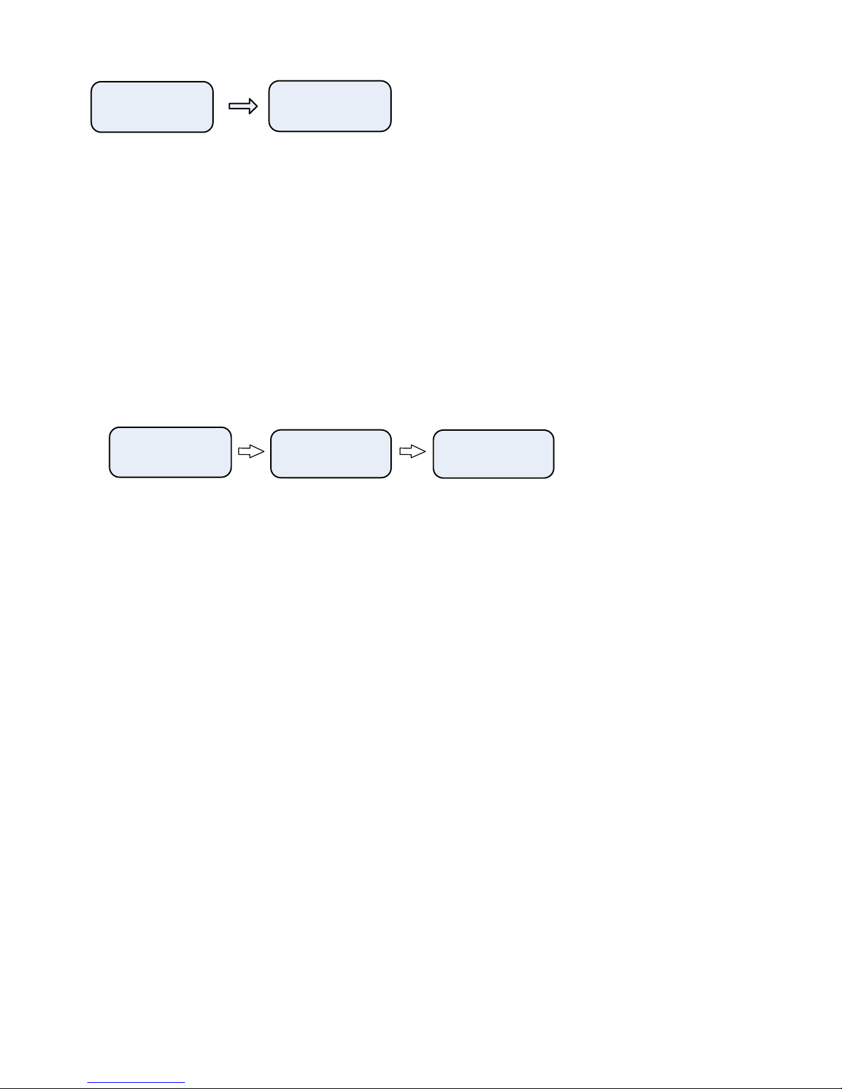
Config
AC MD BR
Ent MD
MagD:+12
Turn On while Holding
the CCW Button
Press the “MODE button
To Enter Declination
[NOTE: Doing a Power-On full Reset operation, all data including the Declination and Calibration data are cleared if the
All’ option is used. A partial Part’ will not clear saved magnetometer calibration and declination data but will clear
direction data.]
To perform a Magnetometer Cali ration, with the Rotor System On, press all three uttons. After the firmware
version is displayed the Function Menu is displayed.
Press the “CW” utton to select the Cali rate function. The Cali rate System su -menu is displayed. Press the “CCW”
utton to select the Cali rate Magnetometer option. The message “Stand By / Mag Cal” is displayed and oth the
Green and Red LEDs will alternately flash at a ½ second duty cycle.
The cali ration cycle takes approximately 12 minutes to complete. The system moves the sensor through 180 degrees
of elevation movement, then moves the azimuth y 30 degrees and then rotates the elevation unit ack 180 degrees.
This cycle repeats 6 times taking samples as the sensor moves. At the end of the cali ration cycle, the data is saved
and used to calculate the correction factor for hard metal and other magnetic interference sources.
Press all buttons brings
up the Function Menu
Function
GP VO CA
CalibSys
CM AC
Press the “CCW buttons
to calibrate the sensor
Stand By
Mag Cal
Calibration process
Is active
When the LEDs stop flashing the process if finished.
Operation:
The Automatic Antenna Cali ration feature has two modes of operation; Manual and Automatic.
When in the Manual Mode, from the Cali rate System su -menu, press the “CW” utton for Antenna Cali ration. The
system will attempt to position the antenna to 0/0 degrees. The antenna direction must e within +/- 45 Degrees of True
North and +/- 10 degrees of level with (0 Degrees Elevation). The Manual or Automatic Antenna Cali ration function will
not e done if the Cali ration Process has not een done first.
When using the Auto Turn Function, a turn to 0 degrees Azimuth and 0 degrees Elevation will cause an Antenna re-
cali ration after returning to 0:0 degrees.
When in the Remote Mode of operation, any computer commanded turn to 0 degrees Azimuth and 0 degrees Elevation will
cause an Antenna re-cali ration after returning to 0:0 degrees. This can e automated y configuring the tracking
application to park at 0:0 degrees
Operational Summary
:
Before Operation:
•Install the Magnetometer
•Enter Declination in degrees
•Perform a Magnetometer Cali ration
Field Deployment
•Place antenna in a Northerly Direction and relatively level