EnglishDeutsch
 logo
Brands
  1. Home
  2. •
  3. Brands
  4. •
  5. Kathrein
  6. •
  7. Antenna
  8. •
  9. Kathrein ZAS 40 User manual

Kathrein ZAS 40 User manual

This manual suits for next models

3

Other Kathrein Antenna manuals

Kathrein K 70 55 64 User manual

Kathrein

Kathrein K 70 55 64 User manual

Kathrein K 70 57 21 04 1 User guide

Kathrein

Kathrein K 70 57 21 04 1 User guide

Kathrein UHF-ANTENNEN OLYMPIA AOI 65 User manual

Kathrein

Kathrein UHF-ANTENNEN OLYMPIA AOI 65 User manual

Kathrein CAS 80gr User manual

Kathrein

Kathrein CAS 80gr User manual

Kathrein HDP 850 GPS User manual

Kathrein

Kathrein HDP 850 GPS User manual

Kathrein UHF-ANTENNEN OLYMPIA AOI 65 User manual

Kathrein

Kathrein UHF-ANTENNEN OLYMPIA AOI 65 User manual

Kathrein UAS 572 User manual

Kathrein

Kathrein UAS 572 User manual

Kathrein Euroline Series User manual

Kathrein

Kathrein Euroline Series User manual

Kathrein CAS 09 User manual

Kathrein

Kathrein CAS 09 User manual

Kathrein CAS 06 User manual

Kathrein

Kathrein CAS 06 User manual

Kathrein 742270V03 User manual

Kathrein

Kathrein 742270V03 User manual

Kathrein CAS 075 User manual

Kathrein

Kathrein CAS 075 User manual

Kathrein BAS 60 Instruction Manual

Kathrein

Kathrein BAS 60 Instruction Manual

Kathrein CAS 120 User manual

Kathrein

Kathrein CAS 120 User manual

Kathrein CAS 120 User manual

Kathrein

Kathrein CAS 120 User manual

Kathrein 80010735V01 User manual

Kathrein

Kathrein 80010735V01 User manual

Kathrein 506 10004 User manual

Kathrein

Kathrein 506 10004 User manual

Kathrein CAS 90gr User manual

Kathrein

Kathrein CAS 90gr User manual

Kathrein BAS 62 User manual

Kathrein

Kathrein BAS 62 User manual

Kathrein UAS572 User manual

Kathrein

Kathrein UAS572 User manual

Kathrein EAS 124 User manual

Kathrein

Kathrein EAS 124 User manual

Kathrein BZD 30 User manual

Kathrein

Kathrein BZD 30 User manual

Kathrein CAS 180 User manual

Kathrein

Kathrein CAS 180 User manual

Kathrein 214125 User manual

Kathrein

Kathrein 214125 User manual

Popular Antenna manuals by other brands

Alfa Network APA-L01 Specifications

Alfa Network

Alfa Network APA-L01 Specifications

Naval PR-422CA Operation manual

Naval

Naval PR-422CA Operation manual

Feig Electronic ID ISC.ANTH200/200 Series manual

Feig Electronic

Feig Electronic ID ISC.ANTH200/200 Series manual

TERK Technologies TV44 owner's manual

TERK Technologies

TERK Technologies TV44 owner's manual

Directive Systems & Engineering DSE2324LYRMK quick start guide

Directive Systems & Engineering

Directive Systems & Engineering DSE2324LYRMK quick start guide

HP J8999A instructions

HP

HP J8999A instructions

MobilSat MSP-S Mounting instructions

MobilSat

MobilSat MSP-S Mounting instructions

Steren ANT-UHF 13 instruction manual

Steren

Steren ANT-UHF 13 instruction manual

Novatel 600-G User information

Novatel

Novatel 600-G User information

Radio Shack Amplified VHF/UHF/FM Indoor Antenna owner's manual

Radio Shack

Radio Shack Amplified VHF/UHF/FM Indoor Antenna owner's manual

TRENDnet TEW-AO12O Specifications

TRENDnet

TRENDnet TEW-AO12O Specifications

Radio Shack 15-1837 owner's manual

Radio Shack

Radio Shack 15-1837 owner's manual

CommScope CMAX-OMFX-43M-I53 Installation instruction

CommScope

CommScope CMAX-OMFX-43M-I53 Installation instruction

Ramsey Electronics DAP25 Kit assembly and instruction manual

Ramsey Electronics

Ramsey Electronics DAP25 Kit assembly and instruction manual

COBHAM SAILOR 800 VSAT Replacement procedure

COBHAM

COBHAM SAILOR 800 VSAT Replacement procedure

Trango Systems AD900-9 Specification sheet

Trango Systems

Trango Systems AD900-9 Specification sheet

Steren ANT-100 user manual

Steren

Steren ANT-100 user manual

IWCS iriBelt II Quick start user guide

IWCS

IWCS iriBelt II Quick start user guide

https://manuals.online logo
https://manuals.online logoBrands
  • About & Mission
  • Contact us
  • Privacy Policy
  • Terms and Conditions

Copyright 2026 Manuals.Online. All Rights Reserved.

1 / 2
ZAS 40 20410011
ZAS 41 20410012
Rafter fasteners for the sat antennas CAS 06/60/80/90 and KEA 650/750/850/1000
About this guide
This document is part of the product.
►Do not install or use the device until you have read and understood
this document.
►Perform all operating steps described in this manual in the specified
sequence.
►Keep this document for reference throughout the service life of the
device. Pass this document on to any new owner or user.
For the most up-to-date version of this document, go to
www.kathrein-ds.com.
Features
■TÜV certified for parabolic antennas with a diameter of up to Ø1m
■ZAS 41 for one parabolic antenna
ZAS 41 for one parabolic antenna and an additional VHF antenna
■Mounting directly from the outside or through the battens onto the
rafter
■Flexibly adjustable to the gaps between the rafters by means of a
telescopic tube
■Continuously adjustable for any roof slope (limited only by the cover
plate)
■Hot-dip galvanised
■Cable is inserted through mast tip by means of the ZTC 08 (included
in the scope of delivery of the ZTS40/ZTS 41ro/ZTS 41sw)
■Designed to withstand lightning current (100kA, 10/350 µs according
to DIN VDE 0855-300)
Scope of delivery
●Rafter fastener
●6wood screws 10x100mm
●Earthing terminal
●Mast cover
●4 nuts M10
●Fastening screw M10 x 20
●User manual
ZAS 40 and ZAS 41 are rafter fasteners for mounting parabolic antennas with a diameter of up to Ø100cm on the roof.
Any other use, or failure to comply with these instructions or documentation and instructions enclosed with the devices, will result in voiding of
warranty or guarantee.
Intended use
Technical data
Type Unit ZAS40 ZAS41
Order no. 20410011 20410012
Length mm 900 1300
Diameter mm 48 48
Gaps between rafters mm 510–900
Roof slope ° 0–90
Rafter frame dimensions mm 580–980x148x40
Suitable for sat antennas CAS06/CAS60/CAS80/CAS90, KEA 650/750/850/1000
Suitable mounting accessories see „Mounting sets ZTS40/ZTS 41ro/ZTS 41sw“ on page <?>
Packing unit mm 940 x 190 x 115 1350 x 190 x 115
Perm. bending moment Nm 700
Packing unit/weight, approx. pc./kg 1/6.5 1/7.5
Mounting sets ZTS40/ZTS 41ro/ZTS 41sw
●For securing the rafter fasteners ZAS 4x
●Consists of:
–ZTB 61: Lead cover plate (410 x 410 mm)
ZTB 60ro/ZTB 60sw: Aluminium cover plate (500 x 450 mm)
–ZTC 08: Mast cap for insertion of eight or ten cables
–ZTC 48: Cover collar (ø 48mm)
The items in the sets are
also available individually.
Please find further moun-
ting accessories under
www.kathrein-ds.com
2 / 2
www.kathrein-ds.com | support@kathrein-ds.com 936500101/g/A4/STM/1121/GB |Subject to change.
KATHREIN Digital Systems GmbH | Anton-Kathrein-Str. 1–3 | 83022 Rosenheim | Germany | Phone +49 731 270 909 70
Installation
Safety instructions
WARNING!
Danger of falling during assembly work on the roof
.
►The equipment described may only be installed by trained specialist personnel.
►Make sure that the supporting structure has sucient load-bearing capacity.
►Wear stable shoes with non-slip soles.
►Make sure that the roof and climbing aid are dry, clean and non-slip.
►Mount the sat antenna (max. ø 100 cm) only up to a height of 800 mm (see sticker marking).
►For a mast length of 1300mm (ZAS 41), install the reflector below and the FM antenna above.
Required tools
●Drill bit Ø 6.5mm
●17 AF open-ended spanner
●Spirit level
Installing the rafter fastener
1. Remove a sucient number of roof tiles.
2. Extend the rafter fastener to the width of rafters or counter
battens.
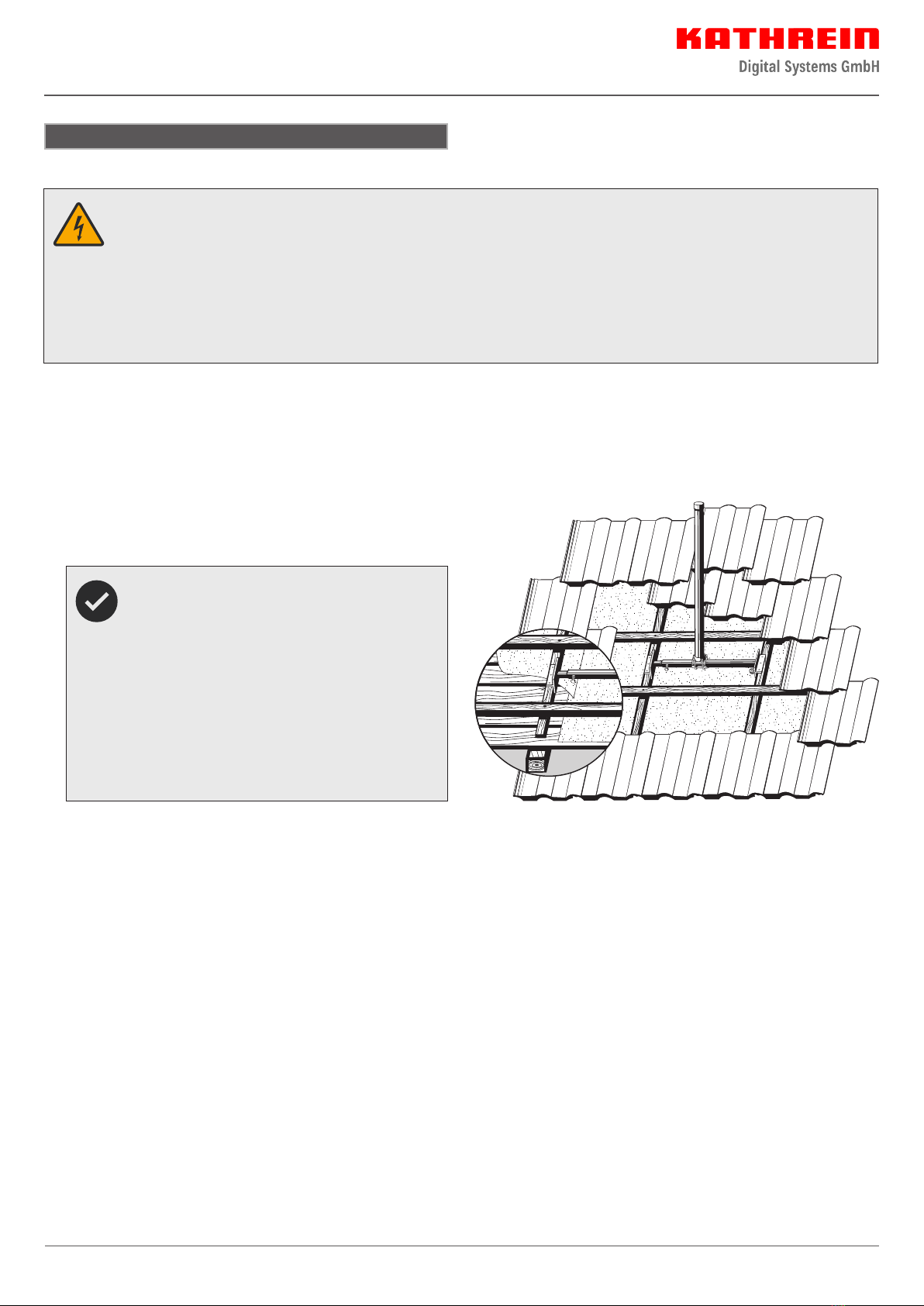
Align the rafter fastener and the lead cover plate to
suit the covering materials of the roof. Take care to
leave enough overhang above and below the gap in
the roofing material.
The cross-tube of the ZAS 40 and ZAS 41 rafter faste-
ners has an oset of about 2 cm relative to the side
securing clips. Depending on the alignment, this
oset allows the rafter fastener to be moved upwards
or downwards within the roof space and, for instance,
in the conjunction with the rafter fastener installation
set ZTS 40, to achieve an optimum position relative
to the existing roof tiles. When installing on steeper
roofs, make sure the shorter securing section points
downwards relative to the slope of the roof.
3. Mark six screw holes on rafters or counter battens.
4. Pre-drill screw holes 50 mm deep using a Ø 6,5 mm drill bit.
5. Screw in the six wood screws 10 x 100 mm from above on
the rafters or counter battens using an A7 19 open-ended
spanner. If the counter battens are too thin, place a suitable
piece of wood underneath the rafter bracket in the areas of
the bolts.
6. Tighten the fastening screw of the telescopic tube using an
AF 17 open-ended spanner.
7. Place the earthing wire (16 mm2copper or 25 mm2alumi-
nium) into the earthing terminal and tighten the nut.
8. Slide the mast along the telescopic tube in such a way that
the cover plate matches the joints of the roof tiles.
9. If you intend to lead cables through the mast tip, remove the
mast cap.
10. Swing the mast towards the gable and pull the cover plate
and the cover collar over the mast tip.
11. Mark six screw holes on rafters or counter battens.
12. Pre-drill screw holes 50 mm deep using a Ø 6,5 mm drill bit.
13. Screw in the six wood screws 10 x 100 mm from above on
the rafters or counter battens using an A7 19 open-ended
spanner. If the counter battens are too thin, place a suitable
piece of wood underneath the rafter bracket in the areas of
the bolts.
14. Tighten the fastening screw of the telescopic tube using an
AF 17 open-ended spanner.
15. Place the earthing wire (16 mm2copper or 25 mm2alumi-
nium) into the earthing terminal and tighten the nut.
16. Slide the mast along the telescopic tube in such a way that
the cover plate matches the joints of the roof tiles.
17. If you intend to lead cables through the mast tip, remove the
mast cap.
18. Swing the mast towards the gable and pull the cover plate
and the cover collar over the mast tip