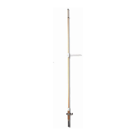
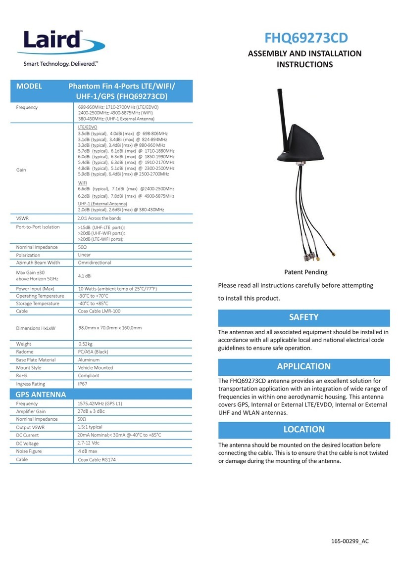
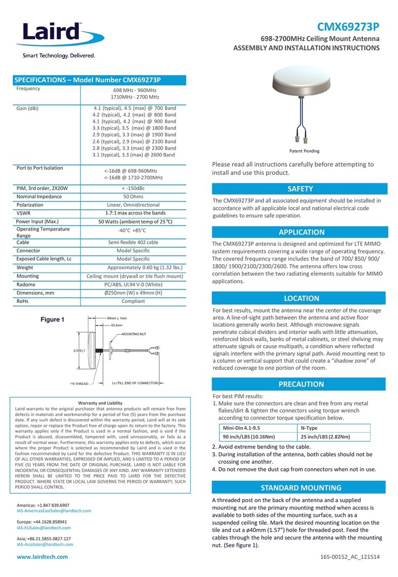
Laird Cushcraft MA6VA Instruction manual

Assembly
and
Installation
Instructions
Cushcraft
MA6VA
Six-Band
HF
Vertical
Antenna
For
20,
17, 15, 12, 10,
and
6
Meters
2
unit
of
@CUSHCRAFT|
Laird.,
958165_GF_AB

General
Description:
The
MA6VA
is
a
light-weight
ground-independent
vertical
covering
20,
17,
15,
12,
10,
and
6
Meters.
Parallel
resonators
provide
automatic
band
switching
and
interaction-free
tuning
adjustments
for
each
band.
The
MA6VA
uses
a
unique
OCFD
(off-center
fed
dipole)
configuration
that
delivers
a
50-Ohm
match
on
all
bands
without
need
for
an
external
matching
network
or
tuner.
Weighing
only
six
pounds,
it
transports
easily
and
sets
up
quickly
for
portable
use.
At
fixed
locations,
mounting
high
in
the
air
with
low-
cost
TV
hardware
allows
it
to
outperform
heavier
multi-band
verticals
installed
close
to
the
ground.
Before
assembling,
please
read
the
manual
carefully
to
become
familiar
with
all
procedures.
Also,
please
check
package
contents
against
the
parts
list
below
to
ensure
all
items
are
included.
Hardware
[]
6
030407
Small
worm
clamp
[]
2
030411
Large
worm
clamp
[]
2
010096
3/8"
x
8-32
screw
{]
8
010009
5/8”
x
8-32
screw
[]
2
010229
1”
x
8-32
screw
{]
2
010040
1-1/4"
x
8-32
screw
[]
3
010123
1-1/2"
x
8-32
screw
[]
2
014544
#8
flat
washer
[]
17
011941
#8
lock
washer
{]
19
010011
8-32
nut
[]
2
360941
#10
flat
aluminum
spacer
washer
[]
1
010084
1/4”
lock
washer
[]
2
010085
1/4"
nut
{]
2
010405
5/16”
—
18
x
2-1/8"
x
4-1/2" U-bolt
[]
8
010119
5/16"
lock
washer
[]
4
013402
5/16”
flat
washer
El
12
010118
5/16”
nut
Components
[]
4
195548
Base
bracket
[]
2
195726
V-bracket
[]
2
194174
8-rod
radial
ring
plate
[]
2
196242
Radial
ring
support
bracket
[]
1
195561
Large
90°
mounting
bracket
[]
4
193853
Small
90°
mounting
bracket
{]
4
205560
Black
plastic
insulator
plate
Ll
1
MASVAFL
9'
RG-58
feedline
assembly
[]
1
350866
2.4"
OD
#61
mix
balun
core
[]
1
100432
UHF
Barrel
Connector
[]
5
031150
Plastic
tie
wrap
[]
6
050077
3/8"
vinyl
end
cap
Tubes
and
Rods
[]
1
MASVBA
1-1/8"
OD
x
12”
aluminum
base
tube
|e
1
MA6VABB
1”
OD
x
54”
insulated
fiberglass
base
tube
[]
1
MASVBC
1-1/8"
OD
x
48”
aluminum
element
tube
{]
i}
MA5VBD
1°
OD
x
48"
aluminum
element
tube
{]
1
MAS5VEA
3/8"
OD
x
6"
resonator
tube
{]
1
MASVEB
3/8"
OD
x
12"
resonator
tube
{]
1
MAS5VEC
3/8"
OD
x
14”
resonator
tube
{]
‘l
MASVED
3/8”
OD
x
18”
resonator
tube
{]
1
MASVEE
3/8”
OD
x
19”
resonator
tube
[]
1
MASV6MEA
3/8"
OD
x
47”
resonator
tube
with
slotted
end
[]
1
082984
1/4"
OD
aluminum
rod
with
threaded
end
ca
2
XHR12
12"
X-hat
rod
[]
8
228161
48”
stainless
radial
rod
with
35°
degree
bend
Resonator
Assemblies
[]
1
MASVRA
10
/
12
Meter
resonator
assembly
[]
1
MASVRB
15/17
Meter
resonator
assembly
|
1
MASVRC
20-Meter
resonator
assembly

Assembly
Instructions
-
MA6VA
[ ]
Step
1:
Install
Base
Tube
on
Insulator
Parts
4
MASVBA
1-1/8"
x
12”
aluminum
base
tube
1
MA6VABB
1"
x
54”
insulated
fiberglass
base
2
010040
1-1/4
x
8-32
screw
2
010011
8-32
hex
nut
Procedure
[ ]
Identify
the
base
end
of
the
insulator
tube
(two
sets
of
mounting
holes
2-3/4"
apart)
[ ]
Install
the
12”
aluminum
the
base
tube
so
mounting
holes
line
up
as
shown
in
Fig-1
[
]
Install
a
1-1/4"
x
8-32
screw
at
A
and
secure
with
a
8-32
nut
[ ]
Install
a
1-1/4"
x
8-32
screw
at
B
and
secured
with
a
8-32
nut
@
1-1/4"
x
8-32
MASVBA
+
1-1/4"
x
8-32
FIG
1:
Base
Insulator
Assembly
[
]
Step
2:
Install
Mast
Mounting
Hardware
Parts
12
010118
5/16"
nut
8
010119
5/16”
lock
washer
2
010405
U-bolt
2
195726
V-bracket
4
195548
Antenna
Base
Bracket
4
013402
Flat
Washer
Procedure
[
]
Find
a
U-bolt
and
install
a
V-bracket
in
opposing
fashion
to
form
a
mast
opening
(A)
[
]
On
each
U-bolt
leg,
install
a
5/16”
flat
washer,
lock
washer,
and
nut.
Spin
nuts
to
expose
2”
of
thread
(B)
[
]
On
each
U-bolt
leg,
install
a
second
nut.
Spin
nuts
to
expose
1-1/8”
of
thread
(C)
[
]
Install
two
opposing
base
brackets
to
form
a
clamp
for
the
antenna
base
(D)
[
]
Loosely
install
the
mast
mount
assembly
at
position
(E)
using
lock
washers
and
nuts
[
]
Repeat
the
assembly
procedure
for
a
second
mounting
assembly
and
install
at
(F)
[
]
Align
clamp
assemblies
by
placing
base
on
a
level
surface
so
all
four
U-bolt
legs
make
contact
[
]
Tighten
end
nuts
to
secure
each
base
clamp
firmly
in
position
®
Mast
Opening
U-bolt
To
Lock
Lock-W
a
a
Flat
level
surface
Fig
2:
Mounting
Clamp
Assembly

[
]
Step
3:
Pre-assemble
Radial
Ring
Parts
eZ
194174
8-rod
radial
ring
2
196242
Radial-ring
support
bracket
8
010009
5/8”
x
8-32
screw
2
360941
#10
aluminum
spacer
washer
(thicker
than
#8
SS
flat
washers)
8
011941
#8
lock
washer
8
010011
#8
nut-
—
-
--——
Procedure
[
]
Locate
two
radial
rings
and
place
together
so
cupped
grooves
oppose
[
]
Install
two
5/8”
screws
from
top
to
bottom,
as
shown
at
A
[
]
From
bottom
side,
install
a
#10
spacer
washer
(B)
and
a
ring-support
bracket
on
each
screw
(C)
[ ]
Secure
assembly
using
lock
washers
and
nuts
(D)
Finger-tighten
only
[ ]
Install
six
5/8”
screws
in
remaining
holes
(E),
securing
with
lock
washers
and
nuts
[
]
Set
assembly
aside
for
later
installation
on
antenna
a,
a
©.
ane
screw
(6)
()
#10
aluminum
=—\S
spacer
washer
‘
=
©
Sock
washer
at
©)
nut
!ock
washer
FIG
3:
Assembly
Detail,
Radial
Ring
[
]
Step
4:
Prepare
Feed
Line
Choke
Parts
1
MASVAFL
Feedline
Assembly
1
350866
2.4"
#61
balun
core
(FT-240-61)
2
031150
Plastic
tie-wrap
Warning:
Avoid
dropping
the
balun
core
when
handling
—
ferrite
material
may
chip
or
break
on
impact.
Procedure
[
]
Find
the
pigtail
end
of
the
feedline
assembly.
Measure
down
42”
from
lugs
and
mark
cable.
[
]
At
42”,
wind
2
turns
of
coax
tightly
around
balun
core
and
secure
in
place
with
a
tie-wrap
(A)
[
]
Continue
winding
for
a
total
of
14
turns
and
capture
the
last
two
turns
with
a
tie-wrap
(B)
[ ]
Arrange
turns
as
needed
for
even
distribution,
as
shown
Connector
end
Start
winding
y
42"
from
connector
Keep
windings
fight
and
fanned
end
of
cable
“pital
Secure
first
2
turns
last2
7
[Ss
counled
with
tie-wrap
turns
with
on
insit
tie-wrap
FIG
4:
Preparation
of
Balun

[
]
Step
5:
Install
Radial
Ring,
Lower
Radiator
Tube,
Coax
Feed.
Parts
1
pre-assembly
Feedline
and
balun
1
pre-assembly
Radial
ring
assembly
1
MA5VBC
1-1/8"
x
48"
aluminum
tube
3
010123
1-1/2”
x
8-32
screw
3
011941
#8
lock
washer
3
010011
8-32
nut
3
031150
Plastic
tie
wrap
Procedure
[ ]
Slide
radial
ring
assembly
onto
insulator
tube
and
position,
as
shown
(A)
[ ]
Identify
the
mounting-hole
end
of
the
48”
aluminum
tube
and
position
at
B,
aligning
mounting
holes
[ ]
Find
pigtail
(lug)
end
of
Feedline.
Also,
find
two
1-1/2”
screws
plus
nuts
and
lock
washers
[ ]
Secure
feedline
shield
and
radial
ring
assembly
to
the
insulator
tube
at
C
[
]
Secure
feedline
center
conductor
and
aluminum
radiator
tube
BC
to
the
insulator
at
D
[
]
Using
three
plastic
tie
wraps,
secure
the
coax
and
balun
to
the
base
insulator
as
shown
in
E
[
]
Install
the
remaining
1-1/2”
screw
and
hardware
at
F
and
secure
MASVAFL
PL259
Connector
1-1/2"
Screw
4-1/2"
x
8-32
Secure
feed
with
3
tie-wraps
Fig
5:
Base
Assembly
and
Coax
Feed
Connection
[ ]
Step
6:
Assemble
and
Pre-adjust
20-Meter
Resonator.
Parts
1
BRAANMNNNA
MA5VRC
20-Meter
resonator
MASVEE
3/8” x
19”
resonator
tube
HXR12
12”
X-hat
rod
010229
1”
x
8-32
screw
011941
#8
lock
washer
010011
8-32
nut
030407
Small
worm
clamp
053368
vinyl
end
cap,
3/8”
053368
vinyl
end
cap,
1/8”

Procedure
[
]
Install
a
12"
X-hat
rod
(A)
as
shown
and
secure
with
a
1”
x
8-32
screw
and
hardware
[
]
Install
the
second
X-hat
rod
in
similar
fashion
[ ]
Place
a
small
worm
clamp
on
the
MA5VRC
as
shown
(B)
[ ]
Install
the
19”
resonator
tube
(C).
Extend
16”
and
secure
in
place
with
worm
clamp
[
]
Install
the
3/8”
vinyl
cap
on
end
of
resonator
tube
at
D
Nut
Lock-W
Smaller
Mtg.
Hole,
_g
Tube
Larger
Mig.
Hole:
:
X-hat
Rod——
1"
Screw
—W
FIG
6:
20-Meter
Resonator
Assembly
[ ]
Step
7:
Install
and
Pre-adjust
17,15,12,
10-Meter
Resonators
Parts
1
MA5SVRA
10/12
meter
resonator
assembly
1
MAS5MRB
15/17
meter
resonator
assembly
y
MASVEA
6"
resonator
tube
1
MASVEB
12"
resonator
tube
1
MASVEC
14"
resonator
tube
1
MASVED
18"
resonator
tube
4
030407
small
worm
clamp
4
050077
vinyl
end
cap
Procedure
[ ]
Position
a
small
worm
clamp
at
the
slotted
end
of
each
resonator
assembly.
[
]
On
MASVRA,
find
10-meter
side
and
install
6”
tube.
Extend
3-3/8”
and
tighten
clamp.
[
]
On
MASVRA,
find
12-meter
side
and
install
12”
tube.
Extend
8-1/4”,
and
tighten
clamp.
[
]
On
MASVRB,
find
15-meter
side
and
install
14”
tube.
Extend
10”
and
tighten
clamp.
]
On
MASVRB,
find
17-meter
side
and
install
18”
tube.
Extend
13-1/4”
and
Sicilaas
clamp.
[
]
Install
a
vinyl
end
cap
on_each
tube.
es
2
=
Band
Identifier
Band
Identifier
Label
Label
Extension
Extension
-e
End
Cap
Small Small
End
Cap
Worm
Clamp
Resonator
Assembly
Worm
Clamp
FIG
7:
Assembly
of
10/12
and
15/17
Meter
Resonators

[
]
Step
8:
Pre-assemble
6-Meter
Resonator
Parts
1
MASV6MEA
3/8"
OD
x
47"
element
tube
(6-meter
resonator)
4
082984
Threaded
aluminum
rod
4
195561
Large
90°
mounting
bracket
1
193853
Small
90°
mounting
bracket
1
205560
Black
Insulator
plate
1
050077
Vinyl
end
cap
1
030407
Small
worm
clamp
2
010096
3/8"
x
8-32
screw
2
014941
#8
lock
washer
2
014544
#8
flat
washer
2
010011
8-32
nut
1
010084
1/4"
lock
washer
2
010085
1/4"
nut
Procedure
[ ]
Find
the
threaded
aluminum
tuning
rod
and
spin
a
1/4”
nut
fully
onto
the
threaded
end
(A)
[ ]
Insert
rod
into
the
large
90°
bracket
(B)
and
secure
with
a
1/4”
lock
washer
and
nut.
[ ]
Using
8-32
hardware,
install
the
black
insulator
plate
on
the
small
90°
bracket
(C)
[
]
Find
the
un-slotted
end
of
the
47”
tube.
Side
the
insulator
to
about
4”
from
the
end
(D)
[
]
Install
a
vinyl
end
cap
on
the
un-slotted
end
of
the
tube
[
]
Install
(loosely)
a
small
worm
clamp
on
the
slotted
end
of
the
element
tube
(F)
[ ]
Set
element
assembly
aside
Insulator
Plate
_
4.
Small
Sy
1/4"Nuts,
worm
3)
47"
Element
Tube
®
i
a
(G)
1
\@
®
Bl
1/4"
Lock
Threaded
Rod
a
Washer
,
r
3/8"
Screw
(x2)
~
Large
90-degree
Flat
Washer
—
Broacket
Insulator
Plate
Small
Bracket
Lock-W
—
Nut
[TT]
FIG
8:
Six-meter
Resonator
Assembly
[
]
Step
9:
Assemble
Upper-Radiator
Parts
1
MA5VBD
1"
x
48”
upper-element
aluminum
tube
1
030411
Large
worm
clamp
2
011941
Lock
washer
2
010011
8-32
nut
1
pre-assembly
20-Meter
resonator
'
1
pre-assembly
15
and
17—Meter
resonator
1
pre-assembly
10
and
12—Meter
resonator

Procedure
[ ]
Find
the
1”
x
48"
aluminum
tube
BD
and
install
a
large
worm
clamp
(loosely)
on
the
slotted
end
(C)
[ ]
Find
10/12-meter
resonator,
install
in
hole
furthest
from
slotted
end
(A).Secure
with
lock
washer
and
nut
[
]
Find
15/17-meter
resonator,
install
in
hole
nearest
slotted
end
(B).
Secure
with
lock
washer
and
nut
[
]
Insert
the
base
of
the
20-meter
resonator
assembly
into
the
slotted
end
of
tube
at
C
[ ]
Set
resonator
for
4-1/2"
of
exposed
aluminum
tube,
secure
in
place
with
large
worm
clamp
20-meter
10/12-meter
Resonator
Resonator
1”
Tube
BC
om
15/17-meter
3)
Resonator
FIG
9:
Mounting
Resonators
[
]
Step
10:
Install
Six-Meter
Resonator
Parts
1
030411
Large
worm
clamp
1
pre-assembly
6-meter
resonator
Procedure
[ ]
Remove
nut
and
lock
washer
fro
ting’screw-atA~——
"
[ ]
Mount
the
tuning-rod
bracket
onde
a6
ies
dline
and
secure
in
place
using
same
hardware
[
]
Position
a
large
worm
clamp
at
C’(dc
Not
tighten).-“-
="
>
.-
-
[
bral
[
[
>
eel
corinne
|
Install
6-meter
resonator
tube
of,allimintitn
tlininig
rod
(B)
and
through
insulator
at
C,
as
shown
]
Capture
insulated
mounting
brack
etl
inder.
the
large
worm
clamp
at
C
and
secure
temporarily
]
Pre-adjust
6-Meter
resonator;
eee
ired
band
segment
(see
chart
below).
Remove
nut
and
lock
washer,
19/5
install
bracket.
ee
Radial
6-meter
Preset
Chart
CW/SSB/AM
[50.150
MHz
_[52-3/4"
FM
Simplex
(50.525
MHz
_|49-3/4"
[Repeater
Pars
[52-54
Whiz
FIG
10:
Installing
6-Meter
Resonator
Assembly

[ ]
Step
11:
Join
Upper
and
Lower
Antenna
Sections
Parts
1
pre-assembly
Antenna
top
section
4
pre-assembly
Antenna
base
section
Procedure
[
]
Find
top-section,
measure
8"
up
from
lower
(un-slotted)
end,
and
place
reference
mark.
[ ]
Loosen
large
worm
clamp
at
A
on
lower
section.
[
]
Insert
top
section
to
8"
mark,
align
6-meter
resonator
parallel
to
main
element,
and
tighten
worm
clamp.
With
6-M
Resonator
Insert
Top
Section
8"
[
]
Step
12:
Install
Radial
Rods.
Important
Warning:
When
working
with
stainless
steel
radial
rods,
always
wear
protective
eyewear
to
prevent
accidental
eye
injury.
“sr
Assembly
Note:
It
is
generally
easier
to
install
drooping
radial
rods
with
the
antenna
supported
upright.
Parts
8
228161
48"
stainless
steel
radial
rod
with
35°
bend
Procedure
[
]
On
the
radial
ring,
loosen
all
eight
5/8”
screws.
[ ]
Insert
radial
rods
between
plates
(A),
installing
so
that
rod
tips
droop
toward
ground.
[
]
Loosely
re-secure
screws.
[
]
Arrange
rod
tips
for
symmetrical
spacing
all
around
and
tighten
hardware
securely.
FIG
12:
Inserting
radial
rods

[
]
Step
13:
Mounting
Antenna
On
Mast
Procdure
[ ]
Spin
nuts
supporting
V-bracket
counter-clockwise
to
enlarge
U-bolt
mast
opening
(A)
[
]
Drop
antenna
onto
mast,
as
shown
(B)
[
]
Used
open-ended
wrench
to
tighten
nuts
securely,
locking
antenna
in
place
(C)
©
Tighten
Loosen
Tighten
FIG-13:
Mounting
Antenna
onto
Mast
General
Setup
and
Installation
Recommendations
[
]
RF-Exposure:
Never
mount
your
MAV6A
where
humans
or
pets
can
make
accidental
contact.
Angular
parts
can
cause
skin
injury
and
RF-energized
metal
surfaces
may
inflict
severe
RF
burns.
Also,
note
that
transmitting
may
expose
nearby
humans
to
intense
RF
fields,
the
medical
effects
of
which
are
unknown
but
may
be
harmful.
U.S.
amateurs
are
required
to
comply
with
FCC
exposure-safety
guidelines.
For
more
information,
see
the
FCC
web
site
at
www.crr.gov./oet/rfsafety
and
the
ARRL
web
site
at
www.arrl.org/news/safety.
Amateurs
in
other
countries
may
also
be
subject
to
local
regulatory
standards.
[
]
Mounting:
Unlike
vertical
monopole
Sth
ly
on
ground
radials,
the
MA6VA
is
a
ground-independent
vertical
dipole
and
mounting
it
too
closéto:the
ground
could
seriously
degrade
performance.
For
best
results,
mount
with
the
counterpoise
rods
elevated
12
feet
off
the
ground
or
higher.
Because
the
antenna
is
+ .
tgs
.
aes.
r .
light
in
weight,
positioning
well
above
th
foofline
is
usually
possible
using
low-cost
TV-antenna
mast
and
hardware.
Avoid
mounting
near
parallel.conductive
surfaces
such
as
metal
buildings,
towers,
hanging
feedlines,
etc.
If
guys
are
required
to
Stabilize’
the
mast,
we
recommend
Phillystran®
or
a
similar
UV-stable
non-conductor.
Do
not
install
metallic.
es
under
the
antenna.
Plan
installation
work
carefully
and
use
only
qualified
persons
to
monitor
or
assist:
When
in
doubt,
obtain
the
services
of
a
professional
installer.
Important
Warning:
Never
install
any
antenna
where
it
could
fall
and
contact
power
or
entrance
lines.
Also,
never
assemble
an
antenna
or
handle
metallic
antenna
components
in
the
vicinity
of.
power
lines.
Death
or
severe
injury
can
result
from
accidental
contact
with
wires
carrying
electrical
power.
[
]
Lightning
Protection:
Nothing
will
protect
your
equipment
from
a
direct
lightning
strike
when
the
feedline
is
connected,
so
always
disconnect
it
from
the
building
when
your
radio
is
not
in
use.
Also,
be
sure
to
ground
the
lower
end
of
any
supporting
mast
using
at
least
two
4’
rods
and
heavy-gauge
wire.
Never
attach
a
lightning-ground
directly
to
the
antenna
feedpoint
—
doing
so
will
bypass
the
balun
choke
and
degrade
performance.
For
secondary
equipment
protection
from
unexpected
nearby
lightning
strikes,
install
a
quality
in-line
arrester
such
as
the
Cushcraft
LAC4.
[
]
Feedline
Selection:
RG-58
is
adequate
for
short
runs
and
RG-8X
(Mini-8)
works
well
up
to
60
feet.
For
longer
runs,
use
RG-8,
RG-213,
LMR-240,
or
LRM-400
to
minimize
loss.
The
supplied
UHF
barrel
connector
may
be
used
for
connecting
male
cable
ends
to
the
MAS5VAFL
male
coax
pigtail.

[
]
Tuning
Procedure:
Our
recommended
resonator
settings
were
gathered
on
an
antenna
range
using
a
sample
MA6VA
tuned
to
14.175,
18.110,
21.225, 24.930,
28.500,
and
52.525
MHz.
Your
settings
could
vary
depending
on
antenna
location,
operating
preferences,
and
normal
manufacturing
tolerances.
When
fine-
tuning,
note
that
extending
the
resonator
tube
lowers
resonant
frequency
and
collapsing
it
increases
frequency.
Make
small
adjustments
(1"
or
less)
and
avoid
over-tighten
and
damaging
the
small
worm
clamps.
For
best
results,
tune
during
dry
weather
conditions
with
the
antenna
positioned
as
close
to
its
final
Operating
position
as
possible.
[
]
Precipitation
Loading:
A
buildup
of
rain
droplets,
ice,
or
snow
will
cause
SWR
curves
to
shift
lower
in
the
band.
Precipitation
detuning
affects
all
antennas,
but
it
is
normally
more
pronounced
for
compact
radiators
like
the
MA6VA.
If
SWR
should
exceed
2:1
on
your
operating
frequency
because
of
inclement
weather,
you
may
use
any
ATU
to
temporarily
compensate
for
the
condition
without
harming
the
antenna.
The
impact
on
on-air
performance
will
be
minimal.
Important
Warning:
The
MA6VA
is
rated
for
250
Watts
PEP.
Attempting
to
use
a
high-power
linear
amplifier
may
result
in
permanent
damage
to
epoxy-encapsulated
resonator
coils.
The
MA6VA
warranty
will
not
cover
resonator
damage
resulting
from
the
application
of
excessive
RF
power.
MA6VA
Specifications
Frequency
Coverage:
20,
17, 15,
12,
10,
6
Meters
Impedance:
50-Ohms
Gain:
1-2
dBi
Minimum
SWR:
1.2:1
typical
at
resonance
Power
Rating
250
Watts
PEP
Wind
Survival
80
mph
Mast
Size:
1-1/4"
—
2-1/8"
(3.18-5.39
cm)
Height
14'7”
(4.48m)
Weight:
6.2
Ibs
(2.81
kg)
2:1
Bandwidth
(kHz)
20m(200),
15m(350),
10m(350)
17m
&
12m
(full
band)
Limited
Warranty
Cushcraft
Corporation,
48
Perimeter
Road,
Manchester,
New
Hampshire
03103,
warrants
to
the
original
consumer
purchaser
for
one
year
from
date
of
purchase
that
each
Cushcraft
antenna
is
free
of
defects
in
material
or
workmanship.
If,
in
the
judgment
of
Cushcraft,
any
such
antenna
is
defective,
then
Cushcraft
Corporation
will,
at
its
option,
repair
or
replace
the
antenna
at
its
expense
within
thirty
days
of
the
date
the
antenna
is
returned
(at
purchaser's
expense)
to
Cushcraft
or
to
one
of
its
authorized
representatives.
This
warranty
is in
lieu
of
all
other
expressed
warranties,
and
implied
warranty
is
limited
in
duration
to
one
year.
Cushcraft
Corporation
shall
not
be
liable
for
any
incidental
or
consequential
damages
which
may
result
from
a
defect.
Some
states
do
not
allow
limitations
on
how
long
an
implied
warranty
lasts
or
exclusions
or
limitations
of
incidental
or
consequential
damages,
so
the
above
limitation
may
not
apply
to
you.
This
warranty
gives
you
specific
legal
rights
and
you
may
also
have
other
rights
which
vary
from
state
to
state.
This
warranty
does
not
extend
to
any
products
which
have
been
subject
to
misuse,
neglect,
accident,
or
improper
installation.
Any
repairs
or
alterations
outside
of
the
Cushcraft
factory
will
nullify
this
warranty.
a
unit
of
@
CUSHCRAFT|
Laird.
48
Perimeter
Road
Manchester,
NH
03103
603-627-7877
FAX
603-627-1764
SPECIFICATIONS
SUBJECT
TO
CHANGE
WITHOUT
NOTICE
Table of contents
Other Laird Antenna manuals

Laird
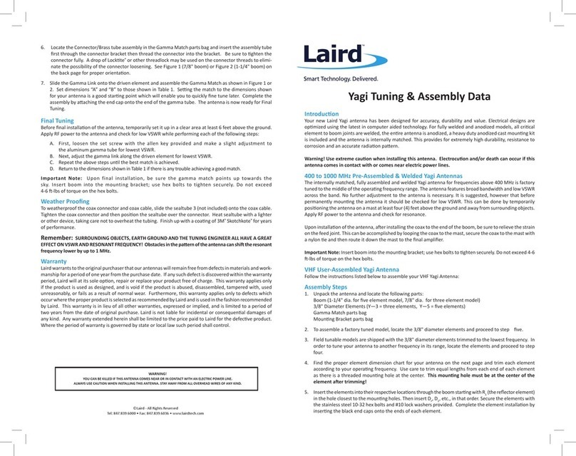
Laird CMX69273P Instruction manual

Laird
Laird Yagi Y1363 User manual

Laird
Laird HDDA5W Series Instruction manual

Laird
Laird VHP69273B22J Instruction manual

Laird
Laird VLT69273B11J Instruction manual
Laird
Laird Phantom Elite Service manual

Laird
Laird S24512BPX User manual

Laird
Laird FHQ69273CD Instruction manual

Laird
Laird VG1506 User manual

Laird
Laird CMS38606P Programming manual
Popular Antenna manuals by other brands

Cisco
Cisco Multiband Diversity Omnidirectional Ceiling-Mount Antenna... Specifications

Topcon
Topcon GX-45 quick start guide

Glomex
Glomex RA1288FME installation guide

Trig Avionics
Trig Avionics TA17 installation guide

1 BY ONE
1 BY ONE O0000-0683 instruction manual

VideoPlus
VideoPlus VP 1000 installation guide