Portawattz 1750 User manual


Portawattz is a trademark of Statpower Technologies Corporation. Copyright 1996, 1997, 1999 Statpower
Technologies Corporation. All rights reserved.
Table of Contents
1. Introduction....................................................................................................2
2. How Your Portawattz 1750 Works...............................................................2
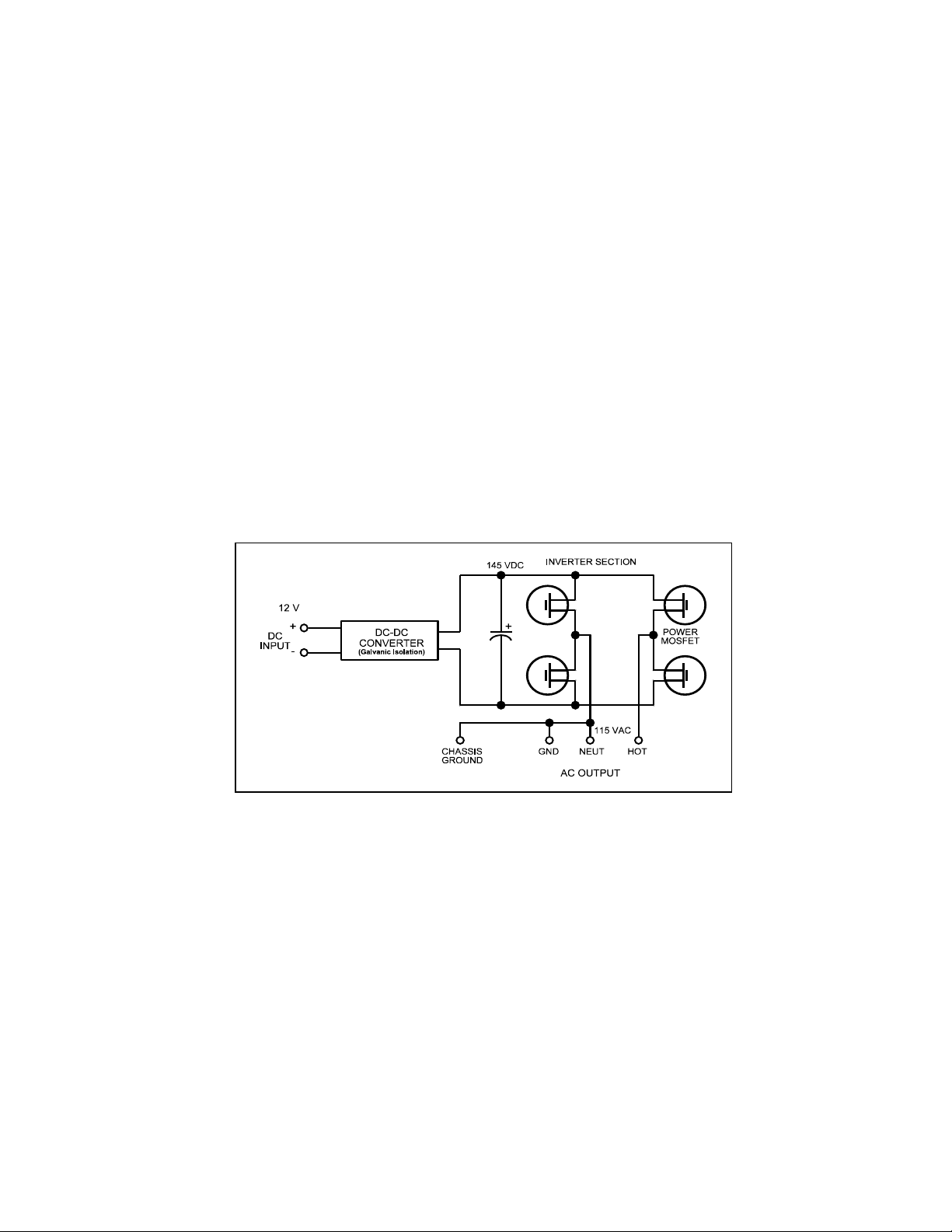
2.1 Principle of Operation........................................................................................3
2.2 Portawattz 1750 Output Waveform....................................................................3
3. Quick Checkout ..............................................................................................4
3.1 Power Source .....................................................................................................5
Battery .........................................................................................................5
DC Power Supply........................................................................................5
3.2 Cables.................................................................................................................5
3.3 Test Loads..........................................................................................................6
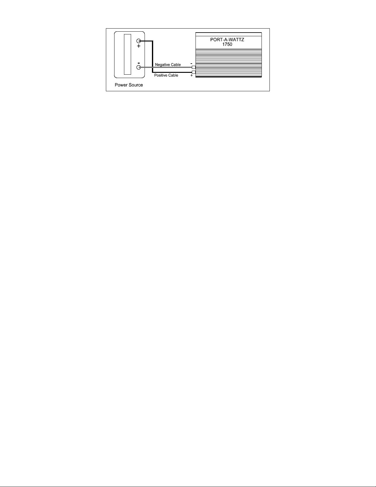
3.4 Connections........................................................................................................7
4. Installation ......................................................................................................9
4.1 Where to Install..................................................................................................9
4.2 Battery..............................................................................................................10
Battery Type ..............................................................................................10
Battery Sizing............................................................................................ 11
Using Multiple Batteries............................................................................14
Battery Tips ...............................................................................................15
Alternators and Charging Systems............................................................. 16
4.3 Cables...............................................................................................................17
4.4 Connections......................................................................................................18
AC Connections.........................................................................................18
Ground Wiring...........................................................................................20
DC Wiring................................................................................................. 21
5. Operation ......................................................................................................23
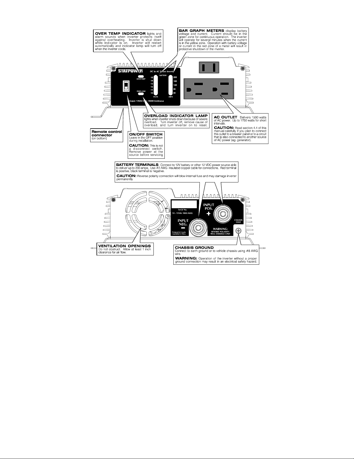
5.1 Controls and Indicators....................................................................................23
5.2 Operating Limits...............................................................................................24
Power Output.............................................................................................24
Input Voltage.............................................................................................25
6. Troubleshooting............................................................................................26
6.1 Common Problems...........................................................................................26
Buzz in Audio Systems..............................................................................26
Television Interference..............................................................................26
6.2 Troubleshooting Guide..................................................................................... 27
7. Maintenance..................................................................................................28
8. Limited Warranty ........................................................................................29
9. Product Specifications..................................................................................31
9.1 Electrical Performance .....................................................................................31
9.2 Dimensions.......................................................................................................31
10. Other Products From Statpower Technologies........................................32

1

2
1. Introduction
Your new Portawattz 1750 inverter is a member of the most advanced line of
DC to AC inverters available today. It will give you years of dependable
service in your boat, RV, service vehicle or remote home.
To get the most out of your Portawattz 1750, it must be installed and used
properly. Please read the installation and operating instructions in this
manual carefully before installing and using your Portawattz 1750. Pay
special attention to the CAUTION and WARNING statements in this
manual and on the Portawattz 1000. CAUTION statements identify
conditions or practices which could result in damage to your Portawattz 1750
or to other equipment. WARNING statements identify conditions or
practices that could result in personal injury or loss of life.
2. How Your Portawattz 1750 Works
An inverter is an electronic device that converts low voltage DC (direct
current) electricity from a battery or other power source to standard 115 volt
AC (alternating current) household power. In designing the Portawattz 1750,
Statpower has used power conversion technology previously employed in
computer power supplies to give you an inverter that is smaller, lighter, and
easier to use than inverters based on older technology.
Figure 1. Principle of Operation

3
2.1 Principle of Operation
The Portawattz 1750 converts power in two stages. The first stage is a DC-
to-DC converter which raises the low voltage DC at the inverter input to 145
volts DC. The second stage is the actual inverter stage. It converts the high
voltage DC into 115 volts, 60 Hz AC.
The DC-to-DC converter stage uses modern high frequency power
conversion techniques that eliminate the bulky transformers found in
inverters based on older technology. The inverter stage uses advanced power
MOSFET transistors in a full bridge configuration. This gives you excellent
overload capability and the ability to operate tough reactive loads like lamp
ballasts and induction motors.
2.2 Portawattz 1750 Output Waveform
The AC output waveform of the Portawattz 1750 is called a "quasi-sine
wave" or a "modified sine wave". It is a stepped waveform that is designed
to have characteristics similar to the sine wave shape of utility power. A
waveform of this type is suitable for most AC loads, including linear and
switching power supplies used in electronic equipment, transformers, and
motors. This waveform is much superior to the square wave produced by
some other DC to AC inverters.
CAUTION: RECHARGEABLE APPLIANCES
Certain rechargers for small nickel cadmium batteries can be damaged
if connected to the Portawattz. Two particular types of equipment are
prone to this problem:
1) small battery operated appliances such as flashlights, razors,
and night lights that can be plugged directly into an ac
receptacle to recharge.
2) certain battery chargers for battery packs used in hand power
tools. These chargers have a WARNING label stating that
dangerous voltages are present at the battery terminals.
Do NOT use the Portawattz with the above equipment.

4
Figure 2. Modified Sine Wave
This problem does not occur with the vast majority of battery operated
equipment. Most of this equipment uses a separate charger or transformer
that is plugged into the AC receptacle and produces a low voltage output. If
the label on the AC adapter or charger states that the adapter or charger
produces a low voltage AC or DC output (less than 30 volts), the Portawattz
will have no trouble powering this charger or adapter safely.
The modified sine wave produced by the Portawattz 1750 is designed to have
an RMS (root mean square) voltage of 115 volts, the same as standard
household power. Most AC voltmeters (both digital and analog) are
sensitive to the average value of the waveform rather than the RMS value.
They are calibrated for RMS voltage under the assumption that the waveform
measured will be a pure sine wave. These meters will not read the RMS
voltage of a modified sine wave correctly. They will read about 2 to 20 volts
low when measuring the output of the Portawattz 1750. For accurate
measurement of the output voltage of the Portawattz 1750, a true RMS
reading voltmeter, such as a Fluke 87, Fluke 27, Tektronix DMM249, or
B&K Precision Model 391, must be used.
3. Quick Checkout
This section will give you the information you need to quickly hook-up your
Portawattz 1750 and check its performance before going ahead with
permanent installation. You will need the following:
a) a 12 volt DC power source
b) two cables to connect the power source to the Portawattz 1750
c) a test load that can be plugged into the AC receptacle on the
Portawattz 1750.

5
3.1 Power Source
For optimum performance, the power source must provide between 11 and
15 volts DC and must be able to supply sufficient current to operate the test
load. As a rough guideline, divide the wattage of the test load by 10 to
obtain the current (in amperes) the power source must deliver.
Battery
Use a fully-charged 12 volt (nominal) battery that can deliver the required
current while maintaining its voltage above 11 volts. A fully-charged (12
volt) automobile battery is capable of delivering up to 50 amperes without an
excessive voltage drop.
DC Power Supply
Use a well regulated DC power supply that has an output voltage between 11
volts and 14 volts and can deliver the required current. If the supply is
adjustable, make sure that the output voltage is adjusted to be between 11
volts and 14 volts. The inverter may shut down if the voltage is outside these
limits and may be damaged if the voltage is above 16 volts. Also ensure that
any current limit control is set so that the power supply can deliver the
required current.
3.2 Cables
Your cables must be as short as possible and large enough to handle the
required current. This is to minimize the voltage drop between the power
source and the inverter when the inverter is drawing current from the power
source. If the cables introduce an excessive voltage drop, the inverter may
shut down when drawing higher currents because the voltage at the inverter
drops below 10 volts.
Example:
Test load is rated at 250 watts.
Power source must be able to deliver
250 ÷ 10 = 25 amperes.

6
We recommend #2 AWG stranded
copper cable that is no longer than 4
ft (1.5 m) if you want to test the
Portawattz 1750 to its maximum
ratings. For short term testing at
reduced power levels, the guidelines
below should be followed.
Ideally, the cable should be no more
than 4 ft (1.5 m) long.
Attach 5/16 inch ring terminals to the ends of the cables to be attached to the
DC terminal studs on the Portawattz 1750. The ring terminals must be
crimped with a proper crimping tool. Another option is to use Ilsco or
equivalent box-lug terminals (available at electrical parts suppliers) sized for
the wire gauge of the cable and for a 5/16 inch stud. The bare cable end is
inserted into the lug terminal and secured with a set-screw.
The other end of the cable, which is connected to the power source, must be
terminated with a lug or other connector that allows a secure, low resistance
connection to be made to the power source. For instance, if the power source
is a battery, the cable must be terminated with a battery terminal that clamps
to the post on the battery.
A SOLID, LOW RESISTANCE CONNECTION TO THE POWER SOURCE
IS ESSENTIAL FOR PROPER OPERATION OF THE PORTAWATTZ 1750.
3.3 Test Loads
Use only equipment rated for 110-120 volt, 60 Hz AC operation that has a
power consumption of 1500 watts or less. We recommend that you start with
a relatively low power load, such as a 100 watt lamp, to verify your test set-
up before trying high power loads.
Power
Consumed
(Watts)
Min. Copper
Cable Size
(AWG)
100 16
250 12
500 8
Table 1 - Test Load Power
Consumption For Short Term Test

7
Figure 3. Connections to the Portawattz
3.4 Connections
Follow the connection sequence described below.
STEP 1 Ensure that the ON/OFF switch on the Portawattz 1750 is in the
OFF position. If the power source is a DC power supply, switch it
off as well.
STEP 2 Connect the cables to the power input terminals on the rear panel of
the Portawattz 1750. The red terminal is positive (+) and the black
terminal is negative (-). Place the cable connector (ring terminal or
box lug) on the stud and then install the supplied lock washer and
nut. Tighten the nut with a wrench to a torque of 9 – 10 ft-lbs (12 –
13 Nm).
STEP 3 Connect the cable from the negative (black) terminal of the
Portawattz 1750 to the negative terminal of the power source. Make
a secure connection.
CAUTION! LOOSELY TIGHTENED CONNECTORS RESULT IN
EXCESSIVE VOLTAGE DROP AND MAY CAUSE OVERHEATED WIRES
AND MELTED INSULATION.
STEP 4 Before proceeding further, carefully check that the cable you have
just connected connects the negative terminal of the Portawattz
1750 to the negative output terminal of the power source. Power
connections to the Portawattz 1750 must be positive to positive and
negative to negative.
CAUTION! REVERSE POLARITY CONNECTION (POSITIVE TO
NEGATIVE) WILL BLOW THE FUSES IN THE PORTAWATTZ 1750 AND
MAY PERMANENTLY DAMAGE THE PORTAWATTZ 1750. DAMAGE
CAUSED BY REVERSE POLARITY CONNECTION IS NOT COVERED BY
YOUR WARRANTY.

8
STEP 5 Connect the cable from the positive (red) terminal of the Portawattz
1750 to the positive terminal of the power source. Make a secure
connection.
WARNING! You may observe a spark when you make this connection
since current may flow to charge capacitors in the Portawattz 1750. DO NOT
MAKE THIS CONNECTION IN THE PRESENCE OF FLAMMABLE
FUMES. EXPLOSION OR FIRE MAY RESULT.
STEP 6 If you are using a DC power supply as the power source, switch it
on. Set the ON/OFF switch on the Portawattz 1750 to the ON
position. Check the meters and indicators on the front panel of the
Portawattz 1750. The voltage bar graph should indicate 11 to 14
volts, depending on the voltage of the power source. If it does not,
check your power source and the connections to the Portawattz
1750. The other indicators should be off.
STEP 7 Set the Portawattz 1750 ON/OFF switch to the OFF position. The
indicator lights may blink and the internal alarm may sound
momentarily. This is normal. Plug the test load into the AC
receptacle on the front panel of the Portawattz 1750. Leave the test
load switched off.
STEP 8 Set the Portawattz 1750 ON/OFF switch to the ON position and turn
the test load on. The Portawattz 1750 should supply power to the
load. If it does not, refer to the troubleshooting section of this
manual. If you plan to measure the output voltage of the Portawattz
1750, refer to Section 2.2 of this manual.

9
4. Installation
4.1 Where to Install
The Portawattz 1750 should be installed in a location that meets the
following requirements:
a) Dry - do not allow water to drip or splash on the Portawattz
1750.
b) Cool - ambient air temperature should be between 0oC and 40o
C (30oF and 105oF) - the cooler the better.
c) Ventilated - allow at least 1 inch (3cm) of clearance around the
Portawattz 1750 for air flow. Ensure that ventilation openings
on the rear and bottom of the unit are not obstructed.
d) Safe - do not install the Portawattz in the same compartment as
batteries or in any compartment capable of storing flammable
liquids such as gasoline.
e) Close to Battery - install as close to the battery as possible in
order to minimize the length of cable required to connect the
inverter to the battery. It is better and cheaper to run longer AC
wires than longer DC cables.
CAUTION! TO PREVENT FIRE, DO NOT COVER OR OBSTRUCT
VENTILATION OPENINGS. DO NOT INSTALL THE PORTAWATTZ 1750
IN A ZERO-CLEARANCE COMPARTMENT. OVERHEATING MAY
RESULT.
WARNING! THIS EQUIPMENT CONTAINS COMPONENTS WHICH
TEND TO PRODUCE ARCS OR SPARKS. TO PREVENT FIRE OR
EXPLOSION DO NOT INSTALL IN COMPARTMENTS CONTAINING
BATTERIES OR FLAMMABLE MATERIALS OR IN LOCATIONS WHICH
REQUIRE IGNITION PROTECTED EQUIPMENT.
Mount the Portawattz on a flat surface using the mounting bracket on the
bottom. Mounting hardware should be corrosion resistant and #10 or larger.
The Portawattz may be mounted horizontally or vertically.

10
4.2 Battery
The battery you use strongly affects the performance you can expect from
your Portawattz 1750. It is important to connect the Portawattz 1750 to the
correct size and type of battery. The following information will help you
select the appropriate batteries for your application.
Battery Type
The lead-acid battery which is probably most familiar is the starting battery
in your automobile. An automotive starting battery is designed to deliver a
large amount of current for a short period of time (so it can start your
engine). Only a small portion of the battery's capacity is used when starting
the engine and it is quickly recharged by the running engine. It is not
designed for repeated charge-discharge cycles where the battery is almost
completely discharged and then recharged. If it is used in this kind of deep
discharge service, it will wear out very rapidly.
Deep-cycle lead-acid batteries are designed for deep discharge service where
they will be repeatedly discharged and recharged. They are marketed for use
in recreational vehicles, boats, and electric golf carts so you may see them
referred to as RV batteries, marine batteries, or golf cart batteries.
Figure 4. Portawattz Connected Directly to Engine
Battery for Light-Duty Application

11
Figure 5. Recommended Battery Configuration
for Medium-Duty Application
For most applications of the Portawattz 1750, Statpower recommends that
you use one or more deep-cycle batteries that are separated from the starting
battery in your vehicle by a battery isolator (as shown in Figure 5). A battery
isolator is a solid-state electronic circuit that allows equipment to be operated
from an auxiliary battery without danger of discharging the vehicle's starting
battery. During vehicle operation, the battery isolator automatically directs
the charge from the alternator to the battery requiring the charge. Battery
isolators can be obtained at marine and RV dealers and most auto parts
stores.
If your application involves relatively low power loads (i.e. average power
consumption of 300 watts or less) and relatively short operating times before
recharging (one hour or less), you may connect the Portawattz 1750 directly
to the vehicle starting battery.
CAUTION! THE PORTAWATTZ 1750 MUST BE CONNECTED ONLY TO
BATTERIES WITH A NOMINAL OUTPUT VOLTAGE OF 12 VOLTS. THE
PORTAWATTZ 1750 WILL NOT OPERATE FROM A 6 VOLT BATTERY,
AND WILL BE DAMAGED IF IT IS CONNECTED TO A 24 VOLT
BATTERY.
Battery Sizing
Unfortunately, there are a number of different standards for rating battery
energy storage capacity. 12 volt automotive starting batteries are normally
rated by cranking amps. This is not a relevant rating for continuous use.

12
Deep-cycle batteries are rated either by reserve capacity in minutes or by
ampere-hour capacity.
Battery reserve capacity is a measure of how long a battery can deliver a
certain amount of current - usually 25 amperes. For instance, a battery with a
reserve capacity of 180 minutes can deliver 25 amperes for 180 minutes
before it is completely discharged.
Ampere-hour capacity is a measure of how many amperes a battery can
deliver for a specified length of time - usually 20 hours. For example, a
typical marine or RV battery rated for 100 ampere-hours can deliver 5
amperes for 20 hours (5 amperes x 20 hours = 100 amp-hrs).
Actual battery capacity decreases as discharge current increases. A battery
rated at 100 ampere-hours that can deliver 5 amperes for 20 hours, may
deliver 20 amperes for only 4 hours, resulting in an actual capacity of 80
ampere-hours. For this reason, it is difficult to compare rated ampere-hour
capacity with battery reserve capacity. For example, a battery with a reserve
capacity of 180 minutes has the following calculated ampere-hour capacity:
180 min. ÷ 60 = 3 hr., 3 hr. x 25 amps = 75 amp-hrs
However its actual ampere-hour rating will be closer to 100 ampere-hours
because it is rated at the discharge current required to get 20 hours of
operation (about 5 amperes).
To determine the battery capacity you require, follow these steps:
STEP 1 For each piece of equipment you will be operating from the
Portawattz 1750, determine how many watts it consumes. This can
normally be found on a label on the product. If only the current
draw is given, multiply the current draw by 115 to get the power
consumption in watts.
STEP 2 For each piece of equipment you will be operating from the
Portawattz 1750, estimate how many hours it will operate between
battery charging cycles.
STEP 3 Calculate total watt-hours of energy consumption, total hours
running time, and average power consumption as in the following
example:

13
Equipment Power
Consumption Operating
Time Watt-Hours (Power
x Operating Time)
TV & VCR 115 watts 3 hours 345
Sewing Machine 150 watts 1 hour 150
Waterpik 90 watts 0.25 hour 22.5
Blender 300 watts 0.25 hour 75
Coffee Maker 750 watts 0.3 hour 225
Coffee Grinder 100 watts 0.1 hour 10
Microwave Oven 800 watts 0.5 hour 400
Totals 5.4 hours 1227.5 watt-hours
Average Power Consumption = 1227.5watt-hours ÷ 5.4 hours = 227 watts
12 volt Ampere-Hours Consumed = Watt-hours ÷ 10 = 1227 ÷ 10 = 123 ampere-
hours
Step 4 Using the chart below (Figure 6), find the battery size that will give
you the required operating time at the calculated average power
consumption. For instance, from the example above, the required
operating time is 5.4 hours and the average power consumption is
227 watts. From the chart, the smallest battery size that will give
more than 5 hours of operation at a power level between 200 and 300
watts is the 200 amp-hr. battery, which offers between 6 and 10 hours
of operating time.
OperatingTimeWithYourBatteries BATTERY
BCIGroupSize 22NF 24 27 8D Dual 8D's
ReserveCapacity(min.) 90 140 180 400 900
Inverter
Output
Power
(Watts) TypicalLoad
12V
Amp
Draw
from
Battery AMPHours 50 75 100 200 400
100 19" Colour TV 10 OPERATING TIME (hrs) 4 6 10 20 40
300 Computer System 30 OPERATING TIME (hrs) 1.3 2.2 3 6 12
400 Power Drill 40 OPERATING TIME (hrs) 1 1.5 2 4.5 10
800 Small Microwave Oven 80 OPERATING TIME (hrs) ** ** ** 1.5 4
1000 Toaster 100 OPERATING TIME (hrs) ** ** ** 1 3
1500 Full size Microwave Oven 150 OPERATING TIME (hrs) ** ** ** 0.5 2
** Not Recommended
Figure 6. 12 Volt Battery Sizing Chart
When sizing your battery, be conservative. More capacity is better since you
will have more reserve capacity, and your battery won't be discharged as
deeply. Battery life is directly dependent on how deeply the battery is
discharged. The deeper the discharge, the shorter the battery life. Ideally,
the number of ampere-hours consumed by your loads before recharging the
battery should be no more than 50% of the battery's rated capacity.

14
Figure 7. Parallel
Connection of Two Batteries
Using Multiple Batteries
To obtain sufficient battery capacity you
may need to use more than one battery.
Two identical batteries can be connected +
to + and - to - in a parallel system (see
Figure 7) that doubles capacity and
maintains the voltage of a single battery.
Do not connect batteries from different
manufacturers, or with different amp-hr
ratings, in parallel. Decreased battery life
may result.
If you are using different batteries, or need to use more than two batteries, we
recommend that you set up two separate battery banks and use them
alternately. Battery selector switches are available from marine and RV
dealers that allow you to select between two banks of batteries, or use both in
parallel, or disconnect both from the load. (See Figure 8 below.)
Figure 8. Recommended Battery Configuration
for Heavy-Duty Application

15
Battery
Voltage Stateof
Charge
12.7 - 12.9 100%
12.5 - 12.6 80%
12.3 - 12.4 60%
12.1 - 12.2 40%
11.9 - 12.0 20%
Battery Tips
1. Lead-acid batteries may emit hydrogen and oxygen gases, and sulfuric
acid fumes when recharging. Vent the battery compartment to prevent
accumulation of these gases, and do not install electronic or electrical
equipment in the battery compartment. Do not smoke or carry an open
flame when working around batteries.
2. The capacity of lead-acid batteries is temperature sensitive. Battery
capacity is rated at 25oC (77 o F). At -20 o C (0 o F) the ampere-hour
capacity will be about half the rated capacity.
3. Do not leave batteries in a discharged state for more than a day or two.
They will undergo a chemical process called sulfation, which can
permanently damage the battery. Also, batteries will self-discharge over
a period of 3 to 6 months, so they should be periodically recharged even
if they are not being used.
4. If your batteries are not the "maintenance-free" type, check the
electrolyte fluid level at least once a month. Use only distilled water to
replenish the electrolyte fluid. Excessive fluid loss is a sign of
overcharging.
5. Connections to battery posts must be made with permanent connectors
that provide a reliable, low-resistance connection. Do not use "alligator"
clips. Clean the connections regularly and prevent corrosion by using an
insulating spray coating or Vaseline.
6. Battery state of charge can be measured with a hydrometer or, more
easily, with a voltmeter. Use a digital voltmeter that can display tenths
or hundredths of a volt when measuring
10 to 30 volts. Make your measurements
after the (12 volt) battery has not been
charged or discharged for several hours.
For a deep-cycle battery at 25 o
C (77 o
F), the following table may be used:

16
Alternators and Charging Systems
A good charging system is important for the health of your batteries. Poor
recharging methods can quickly damage your batteries. When possible,
recharge your batteries when they are about 50% discharged. This will give
you much longer battery cycle life than recharging when the batteries are
almost completely discharged. The Statpower TRUECHARGE family of
battery chargers are designed to maximize your batteries’ performance and
useful life (see your Statpower dealer for more details).
The charging system should be capable of delivering a charging current equal
to 25% of the ampere-hour capacity of your battery. For instance, if you
have a 200 ampere-hour battery, the charging system should be able to
deliver 50 amperes. The charging system must also be able to charge each
12 volt battery up to approximately 14.4 volts and then drop back to a "float"
voltage of 13.5 to 14 volts (or shut off).
A typical engine alternator may not be able to meet these requirements if
large capacity batteries are used. Alternators are typically rated for the
current they can deliver when they are cold. In actual use, alternators heat up
and their output current capability drops by as much as 25%. Thus standard
alternators with ratings of 40 amperes to 105 amperes will only deliver a
maximum of 30 to 80 amperes in actual use and will deliver even less as
battery voltage rises. Many alternators cannot produce more than 13.6 volts
when they are hot. As a result, a standard alternator may not be able to
charge a large battery quickly and completely.
One solution is to install an alternator controller that will bypass the voltage
regulator and boost the alternator’s output voltage during charging. This will
increase the alternator's charging rate at higher battery voltages and ensure
more rapid and complete charging. Alternator controllers are available from
marine product dealers.
Another solution is to install a high-output alternator. Heavy-duty alternators
rated from 100 amperes to 140 amperes are available from RV and marine
dealers, and auto parts suppliers. These alternators are designed to directly
replace standard alternators but produce the higher current and higher
voltage required to charge multiple battery systems.
When recharging from AC power, use a good quality marine battery charger
or RV converter, such as the Statpower TRUEcharge series, that meets the
requirements specified above. Do not use chargers intended for occasional
recharging of automotive starting batteries; these chargers are not intended
for continuous use.

17
Your batteries may also be recharged from alternative energy sources such as
solar panels, wind, or hydro systems. Make sure that you use the appropriate
battery charge controller for your energy source.
Do not operate the Portawattz 1750 directly from a charging source such as
an alternator or solar panel. The Portawattz must be connected to a battery
or a well-regulated, high-current DC power supply to work properly.
4.3 Cables
Proper wire and wiring is very important to the proper operation of the
Portawattz 1750. Because the Portawattz 1750 has a low voltage, high
current input, low resistance wiring between the battery and the Portawattz
1750 is essential to deliver the maximum amount of usable energy to your
load. Don't waste the investment you have made in batteries and a highly
efficient inverter by using undersized wires.
Use only copper wire. Aluminum wire has about 1/3 more resistance than
copper wire of the same size and it is more difficult to make good, low-
resistance connections to aluminum wire.
We recommend #2 AWG copper cable (90° C. insulation rating) as the
minimum size for connections between the battery and the Portawattz 1750.
Keep the cable length as short as possible, ideally no longer than 4 ft (1.5 m).
This will keep the voltage drop between the battery and the Portawattz to a
minimum. If the cables introduce an excessive voltage drop, the inverter
may shut down when drawing higher currents because the voltage at the
inverter drops below 10 volts. If you must use longer cables, then choose
larger cable, such as #00 AWG.
Attach 5/16 inch ring terminals to the ends of the cables to be attached to the
DC terminal studs on the Portawattz 1750. The ring terminals must be
crimped with a proper crimping tool. Another option is to use Ilsco or
equivalent box-lug terminals (available at electrical parts suppliers) sized for
the wire gauge of the cable and for a 5/16 inch stud. The bare cable end is
inserted into the box-lug terminal and secured with a set-screw.
NOTE: It may be necessary to slide the supplied plastic terminal covers
(insulating boots) on to the cables before attaching the terminals.
The other end of the cables, which are connected to the battery, battery
switch, or a fuse block (see Section 4.4), must be terminated with lugs or
other connectors that allow a secure, permanent, low resistance connection to
Other manuals for 1750
1
Table of contents
Other Portawattz Inverter manuals
Popular Inverter manuals by other brands

STMicroelectronics
STMicroelectronics STEVAL-CTM004V1 user manual

Fortress Power
Fortress Power Sol-Ark LFP Legacy Series Guide

Generac Power Systems
Generac Power Systems 8 kW LP owner's manual

SOLARMG
SOLARMG OST-3-8K Quick installation guide

Samlexpower
Samlexpower Evolution EVO-4248SP quick start guide

SMA
SMA 1200 user manual

Toshiba
Toshiba TOSVERT VF-S15 series instruction manual

Victron energy
Victron energy MultiPlus Compact 12 2000 80-30 230V manual

Steamist
Steamist SM-15 Electrical installation instructions

Host
Host HIV10GH1P116 Product instruction manual

Fuji Electric
Fuji Electric Frenic-Mini Supplement to instruction manual

Shihlin
Shihlin SA3 Series user manual