Operation
To operate the power inverter, turn it on using
the ON/OFF switch on the front panel. The power
inverter is now ready to deliver AC power to your
loads. If you are operating several loads from
the power inverter, turn them on separately after
the inverter has been turned on. This will ensure
that the power inverter does not have to deliver
the starting currents for all the loads at once.
AC power. To operate properly connect inverter
DC input terminals direct to battery with heaviest
wire available see chart below:
Max Watts Out Approx. Amps
100W
150W
300W
600W
1000W
1200W
1500W
1800W
2500W
10A
15A
30A
60A
100A
120A
150A
180A
250A
#16
#16
#12
#6 or 2 X #10
# 4
# 4
# 4
2 X #4
2 X #4
Teq'dWire Gauge
3. Grounding
The power inverter has a lug on the rear panel
"chassis ground". This is to connect the chassis
of the power inverter to the ground. The ground
terminals in the AC outlets on the front panel of
the inverter are also connected to the ground lug.
The chassis ground lug must be connected to a
grounding point, which will vary depending on
where the power inverter is installed. In a vehicle,
connect the chassis ground to the chassis of the
vehicle. In a boat, connect to the boat's grounding
systems. In a fixed location, connect the chassis
ground lug to earth.
The neutral (common) conductor of the power
inverter AC output circuit is connected to the
chassis ground. Therefore, when the chassis is
connected to ground, the neutral conductor will
also be grounded. This conforms to national
electrical code requirements that separately
derived AC sources (such as inverters and
generators) have their neutral tied to ground in
the same way that the neutral conductor from the
utility line is tied to ground at AC breaker panel.
Caution!!
The negative DC input of the power
inverter is connected to the chassis. Do not
install the power inverter in a positive ground
DC system. A positive ground DC system has
the positive terminal of the battery connected
to the chassis of the vehicle or to the grounding
point.
Warning!!
Do not operate the power inverter without
connecting it to ground. Electrical shock hazard
may result.
Troubleshooting
1.Common problems
a. Buzz in audio systems:
Some inexpensive stereo systems and "boom boxes" will emit a buzzing noise from their loud
speakers when operated from the power inverter. This is because the power supply in the
device
does not adequately filter the
modified sine wave produced by the power
inverter.
The only solution is to use a sound system that incorporates a higher quality power supply.
(24V spec). If the voltage drops below 10.5V
(
12V spec.) or 21.0V (24V spec.), an audible
low battery warning will sound, and LCD
shows ERR LOW.
The power inverter will also shut down if the
input voltages exceed 16V (12V spec.) or 32V
(24V spec). If the voltage are shut down because
of high input volt protection, an audibel high
battery warning will sound, and LCD shows
ERR HIGH
※
The error of above spec is ±0.5V (for 12V),
±1.0V (for 24V)
!
!
Ensure the ventilation openings on the rear
and bottom of the unit are not obstructed.
d. Safe -
Do not install the inverter in the same
compartment as batteries or in any compartment
capable of storing flammable
liquids such
as gasoline.
2. Cables
DC to AC inverters requires high amperage/low
voltage DC power to low amperage/high voltage
Maintenance
Very little maintenance is required to keep your inverter operating properly. You should clean
the exterior of the unit periodically to prevent accumulation of dust and dirt. At the same time,
tighten the screws on the DC input terminals.
Warranty
We offer 12 months warranty from the date of purchase and will repair or replace any defective
power Inverter ,this limited warranty is void if the unit is abused,modified,installed improperly,
if the housing has been removed,if the serial number is missing,or if the original identification
markings have been defaced,altered,or removed.
The supplier is not liable for any incidental, consequential or other damages arising from the use,
cost of removal,installation,or troubleshooting of the customer's electrical systems.
This is only warranty and the company makes no other warranties, express or implied, including
warranties of merchantability and fitness for a particular purpose.
Repair or replacement are your sole remedies and shall not be liable for damages, whether direct,
incidental, special or consequential, even though cause by negligence or other fault.
-Move the television as far away from the power
inverter as possible.
-
Keep the cables between the battery and the power inverter as short as possible and twist them
together
with about 2 to 3 twists per 30cm /foot. This
minimizes radiated interference from the
-Do not operate high power loads with the power
inverter while watching television.
-
Make sure that the antenna feeding your television provides an adequate ("snow free") signal
and that you are using good quality cable
between the antenna and the television.
b. Television interference:
Operation of the power inverter can interfere with television reception on some channels. If this
situation occurs, the following steps may help to alleviate the problem.
-
Make sure that the chassis ground lug on the back of the power inverter is solidly connected to
the ground system of your vehicle, boat or
home.
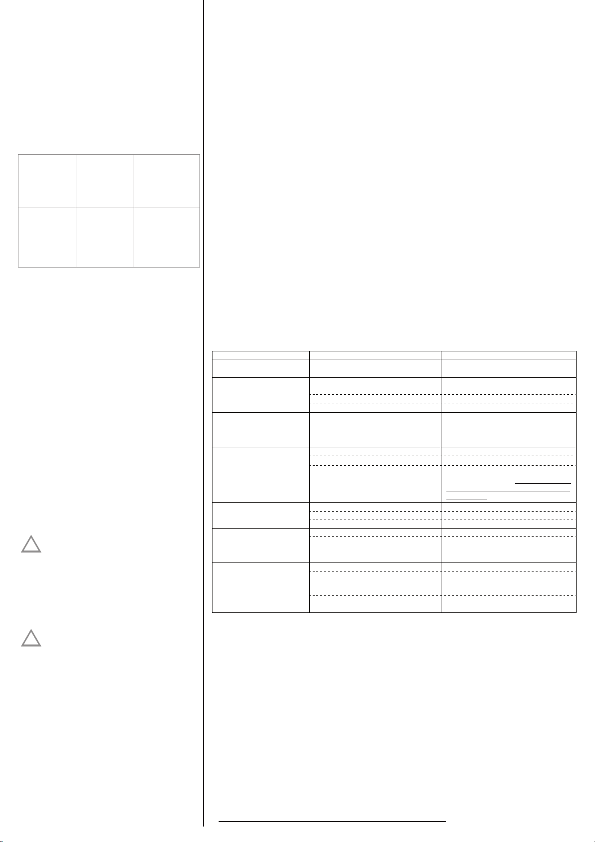
2.Troubleshooting guide
※ Note: Specifications subject to change without notice.
Short circuit or wiring error
Problem Possible cause Solution
Low output voltage
Low input voltage
No output voltage
and display shows
" LVP " or " ERR LOW "
(low volt protection)
No output voltage ,
and no power LED
Low battery alarm on
all the time
No output voltage and
overtemp indicator on
No output voltage and
display shows " OLP "
or “OVR LOAD ”
(over load protection)
Using a voltmeter which can't properly
read the RMS voltage well
Poor battery condition
Low input voltage
Inverter off
Thermal shutdown
Use a true RMS reading meter
Check the batteries and the vehicle
alternator condition
Recharge the battery, check the
connections and cables.
Turn the inverter on
Reduce load
Check AC wiring
Overload
Improper Installation
Reduce load
Check each inverter's installation steps
No DC power to the inverter
Reverse DC polarity
Check the wiring
Check fuse and the installation
Replace the inverter. Damage caused
by reversed polarity is not covered by
the warranty
Poor battery condition Charge or change battery
Poor DC wiring
Use proper cables and check connection
Poor DC terminal connections Use proper tool
Improper installation Allow inverter to cool off
Improve ventilation
Install properly
Inverter overload
Improper installation
Remove or reduce load, switch the
inverter OFF at least 5 seconds and
restart the
inverter
Check the AC wires and improper polarity.
cables.
Operating limits
1.Input voltage
The power inverter will operate from input voltage
ranging 10.0V-16V (12V spec.) or 20V - 32V


