POSITECTOR 6000 User manual

PosiTector 6000
®
Quick Guide v. 7.4
Coating Thickness Gages

Table of Contents
Table of Contents
Introduction ......................................................... 1
Quick Start .......................................................... 1
Certification ......................................................... 2
Probes ................................................................. 4
Calibration, Verification and Adjustment ............. 7
Menu Operation .................................................. 9
Cal Settings Menu ............................................... 10
Zero ................................................................ 10
1 Pt Adjust ...................................................... 11
2 Pt Adjust ...................................................... 11
N Lock ............................................................ 12
Cal Lock ......................................................... 12
Cal Memory .................................................... 13
Setup Menu ......................................................... 14
Reset .............................................................. 14
Gage Info ....................................................... 15
Hi Res Mode................................................... 15
Fast Mode ...................................................... 15
Scan Mode ..................................................... 15
Statistics Menu .................................................... 17
HiLo Alarm ..................................................... 17
Memory Management ......................................... 18
Standard Models Menu .................................. 18
Advanced Models Menu ................................ 19
New PA2 ........................................................ 20
New 90/10 ...................................................... 20
Annotate ......................................................... 21
Display ........................................................... 22
Summaries ..................................................... 23
Screen Capture .............................................. 23

Accessing Stored Measurement Data ................ 24
PosiSoft Desktop Manager (PDM) ................. 24
PosiSoft.net .................................................... 25
PosiSoft 3.0 .................................................... 25
PosiSoft Mobile .............................................. 26
Connect Menu ..................................................... 27
Sync Now ....................................................... 27
Auto Sync ....................................................... 27
USB Drive ...................................................... 27
Bluetooth ........................................................ 29
Bluetooth Wireless Printer ............................. 30
WiFi ................................................................ 30
Updates .......................................................... 33
Temperature ........................................................ 34
Power Supply / Battery Indicator ........................ 34
Rechargeable Batteries ................................. 35
Additional Accessories ........................................ 35
Coating Thickness Standards ........................ 36
Troubleshooting - General................................... 38
Probe attempts measurements in the air ....... 38
Thickness readings are inconsistent .............. 38
Gage powers up but will not take readings ... 38
Gage will not print to Bluetooth wireless printer .... 38
Technical Data .................................................... 39
Returning for Service .......................................... 40
Warranty .............................................................. 40

1
Introduction
Introduction
The PosiTector 6000 hand-held, electronic Gage
non-destructively measures the thickness of coatings on all metals,
quickly and accurately. It consists of a Gage body
(Standard or Advanced) and probe (Built-In or Separate).
PosiTector 6000 Kit Contents
- PosiTector 6000 Probe
- Protective rubber holster with belt clip
- Protective Cap for Probe (some probes only)
- Protective Lens Shield
- Wrist strap
- 3 Alkaline AAA batteries
- Quick Guide Instructions
- Nylon carrying case with shoulder strap
- USB Cable
- Precision Plastic Shims
- Certificate of Calibration traceable to NIST
- Two (2) year warranty on Body and Probe
Principles of Operation
Fprobes use the magnetic principle to measure the thickness of
non-magnetic coatings on ferrous metals.
Nprobes use the eddy current principle to measure the thickness of
non-conductive coatings on non-ferrous metals.
FN probes combine the full abilities of both the "F" and "N" probes.
Quick Start
Quick Start
The PosiTector 6000 powers-up when the center navigation button is
pressed. To preserve battery life, it powers-down after approximately
5 minutes of no activity. All settings are retained.
1. Remove the protective plastic cap (if supplied) from probe.
2. Power-up Gage by pressing the center navigation button.
3. Place the probe FLAT on the surface to be measured.
HOLD STEADY. When a valid measurement is calculated, the Gage
BEEPS twice and the measurement is displayed.
4. Lift probe AT LEAST 2 INCHES (5cm) from the surface between
measurements - OR - leave probe on the surface in the same
location for continuous measurements.

2
If memory is ON while continuous measurements are being taken,
only the last value on the display (when the probe is lifted) is
stored into memory. Scan (pg.15) stores ALL measurements into
memory.
Certification
All probes include a Certificate of Calibration. For organizations
with re-certification requirements, instruments may be returned at
regular intervals for calibration. DeFelsko recommends that
customers establish calibration intervals based upon their own
experience and work environment. Based on our product
knowledge, data and customer feedback, a one year calibration
interval from either the date of calibration, date of purchase, or
date of receipt is a typical starting point. Written calibration
procedures are available from DeFelsko Corporation at
no charge.
Golden Rule
Measure your uncoated part first! This quick zero-check
determines if a Calibration Adjustment is needed for your
substrate. (see pg. 10)
Next, lay the included plastic shims onto a bare surface and
measure them individually to ensure the Gage measures a known
thickness within tolerance.
Protective Cap
Some PosiTector 6000 models are shipped with a protective
plastic cap over the probe. Remove this cap prior to use.
Replace it when the Gage is not in use to protect the probe.
Wrist Strap
We recommend attaching and wearing the
supplied wrist strap. 1
2
Plastic Lens Shield
The LCD is covered with a thin plastic film for protection against
fingerprints and other marks during shipment. This film, while
usually removed before using the Gage, can be left in place to
protect against paint overspray. Replacements can be purchased.

3
Adjust Down
Access the Menu
Adjust Up
Restore brightness
after dimming
(Advanced only)
Button Functions- Normal Operation
Typical Screen
Substrate
Current
Measurement
Battery Indicator
Unit of
Measurement
Current Calibration
Setting
(Advanced Only)
Factory Calibration
in Use
USB Port
Standard
LCD
Display
Probe
Connector
PosiTector Body
Advanced model Standard model
Advanced
LCD
Display
Built-in
Probe Style
Separate
Probe Style

4
Magnetic & Eddy Current
Theory of Operation
Theory of Operation
Probes
Probes
The PosiTector 6000 consists of a body and
a probe. A wide selection of interchangeable
probes are available. Each retain their own
unique calibration information. Gage bodies
(Standard or Advanced) accept ALL probes.See
Gage Info (pg. 15) to find your body and probe type. More probe
information is available at www.defelsko.com/p6000.
To disconnect a probe from a body, power-down the
Gage and pull the plastic probe connector horizontally
(in the direction of the arrow) away from the body.
Reverse these steps to attach a new probe.
When powered-up the PosiTector automatically
determines what type of probe is attached and does a self-check.
Coating thickness probes “sense” when they are near metal and
immediately attempt a measurement followed by another every
2 seconds. They stop when removed from the vicinity of metal and
power-down after 5 minutes of no activity.
This continuous measurement feature is intended to allow careful
probe placement on small or odd-shaped surfaces. Ignore all
readings taken before the probe is properly placed.
The PosiTector 6000 probes calculate coating thickness
measurements using either the magnetic principle
(Fprobes - ferrous models) or the eddy current principle
(Nprobes - non-ferrous models). Combination FN probes
(ferrous/non-ferrous) use both principles.
FN probes first attempt a measurement using the magnetic
principle and will display a reading with the letter "F" if the coating
is non-magnetic over steel. If the coating is non-conductive over
metal, then the probe will automatically attempt a measurement
using the eddy current principle and display a reading with the
letter "N” (see also N Lock pg. 12).

Available PosiTector 6000 Probes:
“Regular” - These constant-pressure, stainless
steel probes are hermetically sealed to be totally waterproof -
ideal for underwater use.
”Micro” - ideal for measuring small parts and
hard-to-reach areas. Available in 0, 45 or 90 degree angles.
”Thick” - ideal for thick, protective coatings.
“Xtreme” - ideal for measuring rough and hot surfaces up to 250°
C (500° F). Probe features an Alumina wear face and braided
cable.
For complete details, see:
http://www.defelsko.com/p6000/p6000_probe_details.htm
5
Additional PosiTector Probes:
The PosiTector accepts a number of probe types including
magnetic and eddy current coating thickness, surface profile,
environmental and ultrasonic wall thickness probes. Perform the
latest software Updates (pg. 33) to ensure probe compatibility with
your Gage. For the latest information on probe interchangeability
see www.defelsko.com/probes
Two Probe Styles:
* Built-in - sensor protrudes from bottom of probe connector
* Separate - sensor is attached to the probe connector by a
1.2 meter (3 foot) cable.
(Extended cables lengths available.)

6
Why is Measurement Important?
Dry Film Thickness (DFT) is arguably the single most important
measurement made during the application and inspection of
protective coatings. Coatings are designed to perform their
intended function when applied within a tight DFT range as
specified by the manufacturer. Correct thickness ensures optimum
product performance. Even the most basic specification will
require DFT to be measured.
Many physical and appearance properties of the finished coating
are directly affected by the film thickness including the color, gloss,
surface profile, adhesion, flexibility, impact resistance, and
hardness of the coating. The fit of pieces assembled after coating
can be affected when film thickness isn’t within tolerance.
Regular film thickness measurement helps control material costs,
manage application efficiency, maintain finish quality and ensure
compliance with contract specifications. Paint manufacturers
recommend target ranges to achieve optimum performance
characteristics and clients expect these parameters to be met.
Precisely measuring finish thickness has other benefits, too.
Whether to meet International Organization for Standardization
(ISO), quality, or customer requirements for process control,
companies need to verify coating quality to avoid wasting money
reworking product.

7
Calibration, Verification & Adjustment
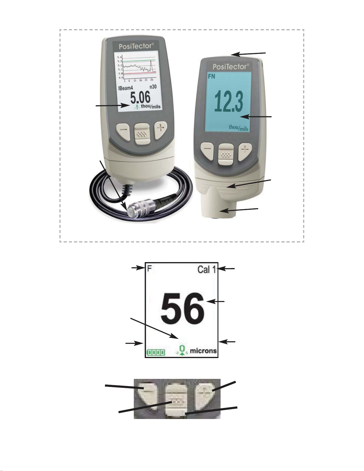
PosiTector 6000 probes non-destructively measure the thickness
of coatings on metals. Three steps ensure best accuracy
1. Calibration - typically done by the manufacturer. All probes
include a Certificate of Calibration.
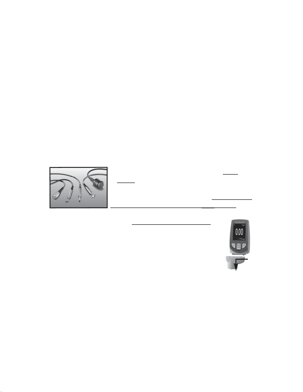
2. Verification - typically done by the user on known reference
standards such as plastic shims or coated thickness standards.
3. Adjustment - to a known thickness
Calibration
Calibration is the high-level, controlled and documented process of
measuring traceable calibration standards over the full operating
range of the probe, and verifying that the results are within the
stated accuracy of the probe. Calibrations are performed by the
manufacturer, their authorized agent, or by an accredited
calibration laboratory in a controlled environment using a
documented process.
PosiTector 6000 probes are shipped with a Certificate of
Calibration showing traceability to a National Metrology Institution.
For organizations with re-certification requirements, probes may
be returned at regular intervals for calibration. DeFelsko
recommends that customers establish calibration intervals based
upon their own experience and work environment. Based on
DeFelsko’s product knowledge, data and customer feedback, a
one year calibration interval from either the last date of calibration,
date of purchase, or date of receipt is a typical starting point.
Written Calibration Procedures are available online at no charge.
Verification
Verification is an accuracy check performed by the user on known
reference standards. A successful verification requires the Gage to
read within the combined accuracy of the probe and the reference
standards.

8
A reference standard is a sample of known thickness(es) against
which a user may verify probe accuracy. Reference standards may
be plastic shims, coated thickness standards, or sample parts
whose coating thickness has been determined using other means.
Verify accuracy at the beginning and the end of each work shift.
During the work shift, if the Gage is dropped or suspected of giving
erroneous readings, its accuracy should be re-verified.
In the event of physical damage, wear, high usage, or after an
established calibration interval, the probe should be returned to the
manufacturer for repair or calibration.
Adjustment
Adjustment, or Cal Adjustment, is the physical act of aligning the
probe’s thickness readings to match those of a known thickness
sample (removal of bias) in order to improve the accuracy of the
probe on a specific surface or in a specific portion of its
measurement range. 1-point or 2-point Cal adjustments are
possible.
Probes are factory calibrated and perform an automatic self-check
each time a measurement is taken. For many applications no
further adjustment is necessary after a Reset (pg. 14). Just check
ZERO on the uncoated substrate, then measure. However,
sometimes probe readings can be influenced by changes in
substrate shape, composition, and surface roughness or by
measuring in a different location on the part. That is why Cal
adjustments are made possible. The XX symbol disappears
whenever a Cal adjustment is made.
Where a Cal adjustment method has not been specified, use a
1-point method first. If measuring the included shims on your
uncoated surface reveals inaccuracies, use the 2-point method.
Factory Cal settings can be restored at any time by performing a
Reset (pg. 14), creating a NEW Cal setting (See Cal Memory
pg. 13), or by DELETING the adjustments made to the Cal 1
calibration setting (pg. 13). The XX symbol appears on the display
whenever factory Cal settings are in use.
With “FN” probes, calibration adjustments are made only to the
“F” or “N” mode (stored independently under a particular Cal),
whichever was measured last.

9
Memory
Statistics
Cal Settings
Setup
Connect
Help
Power Off
Exit
Menu Operation
Menu Operation
Gage functions are menu controlled. To access the Menu,
power-up the Gage, then press the center navigation button.
Below is a sample menu for a PosiTector 6000 Advanced Model:
Up
Down
Center
To navigate, use the Up and Down buttons to
scroll and to SELECT.
Select Exit to exit from any menu.
Navigation Button
The center button is purposely recessed to help
eliminate unintentional powering-up of the Gage.
NOTE:
Some buttons have a tick box to their
right to indicate current status. An empty
box indicates that feature is not active.
Current selection is displayed
with darkened background
Sync Now
USB Drive
Auto SYNC
Bluetooth
WiFi
Powder Probes
Updates
Exit

10
1-point Calibration Adjustment
Also known as an offset or correction value, there are 4 ways to
perform this adjustment:
(i) Simple Zero Calibration Adjustment
Measure your uncoated part. If the Gage does not read "0" within the
tolerance of the probe being used, lift the probe from the surface and
adjust the display down (-) or up (+) until it reads "0". Measure and
adjust until the average of a series of readings on the uncoated
surface is within tolerance of "0" .
(ii) Average Zero Calibration Adjustment
To establish “0” on a rough or curved surface a preferred method
to (i) is to take several readings on the uncoated part and
average the result.
(a) Select from the Cal Settings menu.
(b) Press (+) to select the number of readings to be used to
obtain an average, typically 3 to 10 readings. The greater the
variation between readings, the more readings should be taken
to obtain an average.
(c) Repeatedly measure the uncoated part. The Gage will wait
2 seconds after placing the probe on the surface to allow the
user to correctly position the probe on the surface. After the last
measurement the Gage will calculate a Zero which represents
the average of all the Zero readings taken.
(iii) Simple Adjustment to a Known Thickness
It is sometimes desirable to adjust the Gage to a known
thickness, such as a shim, rather than adjusting it to zero.
Measure the object. If the expected reading is not obtained
(within tolerance), lift the probe from the surface and adjust the
displayed reading down (-) or up (+) to the expected thickness.
Hold the button down to increase the rate of adjustment.
Cal Settings Menu
Cal Settings Menu
Zero
Zero

11
(iv) Average Adjustment to a Known Thickness
On rough or curved surfaces a preferred method to (iii) is to take
several readings on the known thickness and average the result.
(a) Select from the Cal Settings menu.
(b) Press (+) to select the number of readings to be used to
obtain an average, typically 3 to 10 readings. The greater the
variation between readings, the more readings should be taken
to obtain an average.
(c) Repeatedly measure the known thickness reference. The
Gage will wait 2 seconds between readings to allow the user to
correctly position the probe on the surface. After the last
measurement the Gage will calculate and display the reading
which represents the average of all the measurements taken.
If the expected reading is not obtained (within tolerance) lift the
probe from the surface and adjust the reading down (-) or up
(+) to the expected thickness and press .
2-point Calibration Adjustment
Preferred method for very unusual substrate materials, shapes or
conditions. Provides greater accuracy within a limited, defined
range.
1. Select from the Cal Settings menu.
2. Press (+) to select the number of readings to be used to obtain
an average on the thinner item, typically 3 to 10 readings. The
greater the variation between readings, the more readings
should be taken to obtain an average.
1 Pt Adjust
2 Pt Adjust
2 Pt Adjust
1 Pt Adjust
3. Repeatedly measure the thinner item. The Gage will wait for 2
seconds on the surface to allow the user to correctly position the
probe on the surface. After the last measurement the Gage will
calculate and display a thickness value which represents the
average of all the readings taken using the factory calibration
settings.

12
When selected, the icon will appear and all calibration settings
are “locked” to prevent further user adjustments. Uncheck to make
further adjustments.
Cal Lock
Select N Lock (Non-Ferrous Lock) when operating regularly on
non-ferrous substrates. The icon will appear and the probe will
only use the eddy current principle to shorten measurement time
and extend battery life.
N Lock is useful when measuring coatings on plated steel.
Normally the probe measures both the coating + plating over the
steel using the magnetic principle. N Lock makes the Gage
measure the coating over the plating only.
Select N Lock to measure over slightly magnetic substrates; i.e.
clear-coat on gold over nickel-plated brass. Although the probe's
magnet is used for the magnetic principle, it is also used in N Lock
to magnetically saturate a slightly magnetic substrate and allow
the eddy current principle to operate unhindered.
With N Lock engaged it is possible to obtain a reading
when measuring non-conductive coatings on steel. This is not
recommended.
N Lock (FN ferrous/non-ferrous combination probes only)
CAUTION:
4. Lift the probe from the surface and adjust the displayed reading
down (-) or up (+) to the known thickness value of the thin item. Press
to accept this value.
5. Repeat steps 2 - 4 for the thicker item.

13
It is often convenient to store a particular calibration adjustment
before making another. Then, if you return to that part, the
corresponding calibration setting can be restored.
A “setting” is any calibration adjustment. The PosiTector 6000
always displays the current calibration setting (ex. Cal 3) in the
upper right corner of the display.
The setting called Cal 1 has unique features. It can be adjusted
but never deleted, and is always made active with factory settings
after a Reset (pg.14).
Creates a new calibration setting using the next available number
(Maximum of 10). By default, these new Cal settings are initially
created with the Gage’s factory settings. This is indicated with the
icon which appears at the bottom of the display. A warning
message will prevent the creation of a new Cal Memory if a batch
is open and has readings. Delete the batch first (pg. 21).
Removes a setting completely from the list. That Cal number can
be reused later with the New command. A setting cannot be
deleted if readings have been stored into a batch using that
calibration setting. Delete all readings in that batch first (pg. 21).
Although Cal 1 cannot be deleted, the Delete function will return
it to factory settings.
View stored Calibration Settings.
Loads an existing setting. Use the Up or Down buttons to scroll
until the desired setting appears, then press . A warning
message will prevent the opening of a stored Cal setting if a batch
is open and has readings. Create a new batch first or open a batch
containing no readings (pg. 20).
View
Delete
Open
New
Cal Memory (Advanced models only)
Calibration Memory
Calibration Memory

14
Setup Menu
Setup Menu
Reset
Reset (soft reset) restores factory settings and returns the Gage
to a known condition. The following occurs:
- All batches, stored measurements, images, and batch names
are erased.
- The icon will appear on the display.
- Menu settings are returned to the following:
Memory = OFF
High Res = OFF
Statistics Mode = OFF
Hi Lo Alarm = OFF
Scan Mode = OFF
Cal Lock = OFF
Bluetooth = OFF
Display = None
N Lock = OFF
Perform a more thorough Hard Reset by powering down the
Gage, waiting several seconds, then simultaneously holding both
the center and (+) buttons until the Reset symbol
appears. This returns the Gage to a known “out-of-the-box”
condition. It performs the same function as a menu Reset with
addition of:
NOTES: - Keep the Gage away from metal during a Reset.
- Date, Time and WiFi are not affected by either Reset.
Units = microns
Flip Display = Normal
Auto Sync = OFF
White on Black = OFF
Fast Mode = OFF
Language = English
Battery Type = Alkaline
Backlight = Normal
Bluetooth Streaming = OFF
USB Drive= ON
- All calibration adjustments and Cal Memory are cleared and
returned to the Gage’s factory calibration settings.
- Bluetooth Pairing info is cleared.
- Menu settings are returned to the following:

15
Gage Info
Displays the model number & serial number, probe type & serial
number, PosiSoft.net registration key, the amount of remaining
memory for storage of readings, date and time, and software
packages.
For security purposes, the registration key is required to add the
Gage to your free PosiSoft.net account.
Increases the displayed Gage resolution as follows:
Hi Res
Resolution Range
0.01 mil 0.00 - 99.00 mils
0.1 mil 100.0 - 999.9 mils
0.1 um 0.0 - 999.9 um
1.0 um over 1000 um
Gage accuracy is not affected.
NOTE:
Increases measurement speed for most probes. Useful for quick
inspection or when measuring large areas with thick coatings
where proper probe positioning is not critical. Swift up/down probe
movement is required. Reduced accuracy may be noted.
In ordinary operation, the PosiTector 6000 takes thickness
measurements every 2 seconds when placed onto a surface.
Normally, the user raises the probe after it has taken a single
measurement and relocates it to a second location. Scan mode
modifies this behavior in two ways. First, measurements are taken
much faster. Second, all measurements are recorded when
memory is on. As the probe slides along the surface in scan mode,
the PosiTector 6000 takes single measurements in quick
succession. This may reduce the life of the probe. Recommended
for smooth surfaces only.
Scan
Fast
(Advanced models only)

16
Selects display brightness (Sun, Normal or Night). All settings will
dim slightly after a period of no activity to conserve battery life.
Press the Down button to brighten the display.
Backlight (Advanced models only)
All measurements are date and time stamped (24 hour format)
when stored into memory. It is therefore important to keep both the
date and time current using this menu option. Use the Up and
Down buttons to scroll, and the (-) and (+) buttons to adjust a
value. The Gage’s data and time can also be viewed in Gage Info
(pg. 15).
Set Clock
Selects the type of batteries used in the Gage from a choice of
“Alkaline”, “Lithium” or “NiMH” (Nickel-metal hydride
rechargeable). If NiMH is selected, the Gage will trickle charge the
batteries while connected via USB to a PC or optional AC charger
(Gage must be powered ON). The battery state indicator icon is
calibrated for the selected battery type. No damage will occur if the
wrong battery type is selected.
DeFelsko recommends eneloop (NiMH) rechargeable batteries
(pg. 35).
Converts the display from inch to metric or vice versa. Stored
measurements in memory are not converted.
Switching units will turn off Statistics, HiLo Alarm and closes
Memory.
Units
Battery Type
Converts displayed and printed words to the selected language.
Language
Flip Display
This option causes the display to rotate 180°. Ideal for right-side-
up viewing when the sensors are pointed away from the user.
White on Black
Inverts the LCD display to white on a black background to provide
better readability in some surroundings.
(Advanced models only)

17
Allows the Gage to visibly and audibly alert the user when
measurements exceed user-specified limits.
When HiLo Alarm is selected, the current Lo setting is displayed.
Adjust down (-) or up (+). Alternatively, measure a coating with a
thickness close to the required value and make final adjustments
with the buttons. Select NEXT to accept this value. The current Hi
setting is now displayed. Follow the same procedure to adjust the
Hi setting.
The icon will appear on the display.
Measurements will be compared to your defined HiLo limits. The
Gage beeps if results are within those limits. A single low tone will
sound if the reading is below the Lo limit, and a high tone if it is
above the Hi limit. Press (+) to clear HiLo readings.
When selected, a icon and statistical summary will appear on
the display.
Remove the last measurement by pressing the (-) button. Press
(+) to clear statistics.
Clear
Statistics Menu
Statistics Menu
Mean
(average)
Standard
Deviation
# of
measurements
Minimum
measurement
Statistics
Icon
Last
reading
Statistics
HiLo Alarm
Clears all on-screen Statistics and HiLo tabulations.
50
microns
n6
49.8
52 48
x
x
x↨
σ
↨
1.3
Maximum
measurement
Other manuals for 6000
1
Table of contents
Other POSITECTOR Measuring Instrument manuals
Popular Measuring Instrument manuals by other brands

NARDA
NARDA HP-01 user manual

Grace Engineered Products
Grace Engineered Products GraceSense G-HSM-9SM installation guide

PZRacing
PZRacing GearTronic ZERO GT3100-H1 user manual

PCB Piezotronics
PCB Piezotronics 052M94A Installation and operating manual

Fluke
Fluke 5606 user guide

Kanomax
Kanomax 1580 user manual