Positron 7885-2 Operating and installation instructions

Standalone Power Supply Unit
120 V ac to 48 V dc, 7885-2 & 7885-3
Description and Installation

DOCUMENT CONTROL INFORMATION
Document Part Number: 7885-24-02, Rev 4
Document Issue Number: 4
Publication Date: January 07, 2003
Document ID: (o02j2000.fm)
CONFIDENTIALITY NOTICE
The information contained in this document is the property of Positron Inc. Except as specifically
authorized in writing by Positron Inc., the holder of this document: 1) shall keep all information
contained herein confidential and shall protect same in whole or in part from the disclosure and
dissemination to all third parties, and 2) shall use same for operating and maintenance purposes only.
DISCLAIMER NOTICE
Although Positron Inc. has made every effort to ensure the accuracy of the information contained
herein, this document is subject to change without notice.
TECHNICAL CUSTOMER SUPPORT
Should a problem arise, contact your customer support department. If the problem cannot be resolved
by your support department or if you have any questions, contact Positron’s Technical Customer
Support department at 1-888-577-5254.
© 2003 Positron Inc.
Teleline Isolator is a registered trademark of Positron Inc.
Product names, other than Positron’s, mentioned herein may be trademarks and/or registered trademarks
of their respective companies.

Contents i
o02j2000TOC.fm
1. The Standalone Power Supply Unit and Battery Unit . . . . . . . . . . . . . . . . . . . . . . . . . . . . . . . . . . . . 1
2. Hardware Description . . . . . . . . . . . . . . . . . . . . . . . . . . . . . . . . . . . . . . . . . . . . . . . . . . . . . . . . . . . . . 4
3. Technical Specifications. . . . . . . . . . . . . . . . . . . . . . . . . . . . . . . . . . . . . . . . . . . . . . . . . . . . . . . . . . . 6
4. Installation . . . . . . . . . . . . . . . . . . . . . . . . . . . . . . . . . . . . . . . . . . . . . . . . . . . . . . . . . . . . . . . . . . . . . 7
4.1 Mechanical Installation. . . . . . . . . . . . . . . . . . . . . . . . . . . . . . . . . . . . . . . . . . . . . . . . . . . 11
4.1.1 Wall Mount. . . . . . . . . . . . . . . . . . . . . . . . . . . . . . . . . . . . . . . . . . . . . . . . 11
4.1.2 Teleline Shelf Mount . . . . . . . . . . . . . . . . . . . . . . . . . . . . . . . . . . . . . . . . 12
4.2 Electrical Installation . . . . . . . . . . . . . . . . . . . . . . . . . . . . . . . . . . . . . . . . . . . . . . . . . . . . 13
4.3 Battery Replacement Procedure . . . . . . . . . . . . . . . . . . . . . . . . . . . . . . . . . . . . . . . . . . . . 15
5. Service and Support . . . . . . . . . . . . . . . . . . . . . . . . . . . . . . . . . . . . . . . . . . . . . . . . . . . . . . . . . . . . . 17


(20 pages) Standalone Power Supply Unit 120 V dc to -24 V dc 1
7885-2 & 7885-3
o02j2001.fm
1. The Standalone Power Supply Unit
and Battery Unit
The Standalone Power Supply Unit and its Battery Unit, models 7885-2 and
7885-3, are described in one document because together they form a fully
functional uninterruptible power supply. They are always sold together, as a pair.
The Standalone Power Supply Unit, model 7885-2, converts 120 V ac, 60 Hz to
48 V dc, and may be configured for an output that is either floating or referenced
to station ground. This large capacity supply can be used to power a fully loaded
Three, Five or Eight-card Shelf.
The Battery Unit, model 7885-3, holds two maintenance-free backup batteries, as
does the Power Supply Unit, model 7885-2. When the 7885-2 is connected to the
7885-3, the 7885-2 provides 5.7 ampere-hours of battery charge at 48 V dc. The
7885-2 alone cannot provide battery backup.
The installation kit consists of the Standalone Power Supply Unit and its Battery
Unit, in durable, metal enclosures. The kit contains connecting cables, and
mounting hardware.
Attention
The Standalone Power Supply Unit and its Battery Unit are intended to
provide a shelf with uninterruptible 48 V dc, either floating or referenced to
station ground. Teleline equipment having conflicting requirements cannot
be used with this supply. For further information, refer to Table 3 and Table
4.
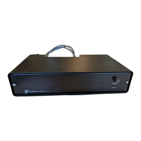
For a view of the Standalone Power Supply Unit and its Battery Unit, refer to
Figure 1.

7885-2 & 7885-3
2 Standalone Power Supply Unit 120 V dc to -24 V dc
Figure 1 Models 7885-2 & 3
3-7/8"
MOUNTING TRAY
7885-2 RIGHT SIDE VIEW
16-1/4"
7885-2 FRONT VIEW
POSITRON # 7885-2
MOUNTING
TRAY
INPUT CABLE
9-2/3"
INPUT FUSE
ANCHORING BRACKET
OUTPUT CONNECTOR
3-7/8"
7885-3 RIGHT SIDE VIEW
16-1/4"
7885-3 FRONT VIEW
POSITRON # 7885-3
9-2/3"
BATTERY
TEST
+
POWER
CHARGE
-
50BC1;>
$0<?

Standalone Power Supply Unit 120 V dc to -24 V dc 3
7885-2 & 7885-3
The features of the unit (comprised of the power supply and battery units)
include the following:
•The unit may be used with both the old and new generation Three, Five or
Eight-card Teleline Shelf.
•The unit provides floating 48 V dc at up to 1.3 A from a standard 120 V ac
source. When wiring to a shelf, the supply output may be left floating or
referenced to station ground.
•The unit uses standard full wave rectification, filtering, and voltage
regulation to perform the AC to DC conversion.
•When model 7885-2 and 7885-3 are connected together, they provide 5.7
ampere-hours of charge at 48 V dc. The batteries are kept charged by the
power supply while it is operating from the AC source.
•A fuse provides overcurrent protection at the input, while a second at the
output provides short circuit protection.
•A green “Power ON”LED located on the front panel indicates the presence
of 48 V dc output.
•A red “CHARGE”LED located on the front panel indicates that the batteries
are undercharged.
•A pair of battery test jacks permit an easy assessment of batteries status.

7885-2 & 7885-3
4 Standalone Power Supply Unit 120 V dc to -24 V dc
2. Hardware Description
For the block diagram of model 7885-2, refer to Figure 2.
Figure 2 Block Diagram
Under
Voltage
Detection
Rectifier
Output
Breaker
Input
Breaker
Transformer Voltage
Regulator
Batteries
Filter
120 V ac in
48 V dc out
(floating)
Current
Limit

Standalone Power Supply Unit 120 V dc to -24 V dc 5
7885-2 & 7885-3
The following is a description of the elements of the Standalone Power Supply
Unit block diagram.
Input Breaker
The Input Breaker circuit on the right side panel of the 7885-2 is a 1 A circuit
breaker providing standard input protection.
Transformer
The Transformer provides 1500 V isolation while stepping down the voltage for
the regulator.
Rectifier
The Rectifier fully rectifies the AC input voltage.
Filter
The Filter is made of a big electrolytic capacitor that filters the 60 Hz input to
provide a DC voltage to the regulator.
Voltage Regulator
The Voltage Regulator takes the filtered voltage from the input and gives out 48
V dc to the output.
Current Limit
The Current Limit circuit is a linear current limit circuit that drops the output
voltage as the current increases past the limit value.
Output Breaker
The Output Breaker circuit on the front panel is rated at 2 A and provides short
circuit protection to the power supply.
Batteries
Each Battery is a 12 V, maintenance-free Dryfit type. They require no more than
24 hours to reach full charge, and can hold 5.7 ampere-hours of charge. This
corresponds to 570 mA over a 10-hour discharge period. Since the four batteries
are connected in series, this current is available at 48 V dc.
Under Voltage Detection
The Under Voltage Detection circuit monitors the batteries and lights a LED
when the voltage approaches the minimum specified voltage of the power supply.

7885-2 & 7885-3
6 Standalone Power Supply Unit 120 V dc to -24 V dc
3. Technical Specifications
For a listing of the unit’s electrical specifications, refer to Table 1. For a listing of
the unit’s physical specifications, refer to Table 2.
Table 1 Electrical Specifications (measured at 77°F or 25°C,
50% R.H.)
Table 2 Physical Specifications
Parameter Specifications
Battery GS Battery 12V, 5.7 A-h
P/N PE12V7F1 or equivalent
Input station voltage 104 to 127 V ac
Input power at full load 160 VA
Nominal output voltage 48 V dc
Maximum output current 1.3 A
Output ripple voltage 400 mVpp
Regulation, line <7.0%
Regulation, load <8.0%
Input/output isolation 1500 V @ 60 Hz for 1 minute
Parameter Specifications
Operating temperature range +32°F to +122°F (0°C to + 50°C)
Height 3.9”(9.9 cm)
Width 16.3”(41.4 cm)
Depth 9.7”(24.6 cm)
Weight (7885-2)
Weight (7885-3)
21 lbs (9.5 kg) approx.
15 lbs (7.0 kg) approx.

Standalone Power Supply Unit 120 V dc to -24 V dc 7
7885-2 & 7885-3
4. Installation
This installation procedure assumes that the Three, Five or Eight-card Shelf
being used has already been mounted as per its installation instructions. For
further information, refer to the Description and Installation documentation for
the Three-card Shelf, model 751127, part number 924-010186-001, Five-card
Shelf, model 751112/1, part number 924-010199-001, or Eight-card Shelf, model
751109/13, part number 924-010040-001.
Caution
Stand on a thick rubber mat and wear rubber gloves during the installation
procedure. It is preferable to perform these procedures on a clear dry day
when a Ground Potential Rise (GPR) or transients are less likely to occur.
1. Verify that you are not using any equipment which is incompatible with the
Standalone Power Supply Unit. For lists of equipment that are compatible
with the unit, models 7885-2 & 3, refer to Table 3 and Table 4. All other
equipment is not compatible with this unit.
2. Verify that you have the following customer supplied tools and hardware
which are required to install the unit:
•Cable from station batteries
•Center punch
•Electric drill with a 5/32”diameter bit
•7/16”hex wrench
•Phillips screwdriver
•Cable clamps and mounting hardware for routing cables exterior to the shelf
(quantity determined by the cable lengths involved).

7885-2 & 7885-3
8 Standalone Power Supply Unit 120 V dc to -24 V dc
Table 3 Case 1: List of Compatible Equipment
Supply Configured for Floating 48 V dc (i.e., Connected Between
-48V and RU GEN)
Plug-in Two-wire AC Data Card 7501-72
Two-wireT1 Carrier Card 7501-06A
Four-Wire T1 Carrier Card 751329
DC Trip/DC Pilot Wire Cards (variations B and C only) 7501-15B, C
OPX Trunk Card (variation B only) 7501-16B
Four -Wire AC Data Card 7501-24
Expandable Telephone Card (configured for -24 V only) 751321 & 751321/A,
751321C
Two-wire HDSL card 751340
ADSL Card (configured for -24V only) 751321B
Advanced Telephone Card (configured for -24 V only) 751317
Line Test Card 751366
-24 V dc Plug-In Power Supplies 751313, 751316,
751324
All -24 V dc Standalone Power Supplies 7715-2, 7715-3,
7856-3
ISDN Card (-24V configuration only) 751333A
Four-wire HDSL Card 751339

Standalone Power Supply Unit 120 V dc to -24 V dc 9
7885-2 & 7885-3
Table 4 Case 2: List of Compatible Equipment
3. Unpack the Standalone Power Supply Unit and its installation hardware
from its box.
4. Check the contents of your Standalone Power Supply Unit kit. For a listing
of the items included in the kit, refer to Table 5.
Supply Configured for -48 V dc w.r.t. Station Ground (i.e., Connected Between -48 V and
Ground)
Two-wire T1 Carrier Card 7501-06A
Four-Wire T1 Carrier Card 751329
DC Trip/DC Pilot Wire Card (variation B only) 7501-15B
OPX Card (variations B and C only) 7501-16B, C
Four-Wire AC Data Card 7501-24
Two-Wire AC Data Card 7501-72
Expandable Telephone Card (configured for -24 V or 48 V) 751321 & 751321/A,
751321C
Line Test Card 751366
-24 V dc Plug-In Power Supplies 751313, 751316,
751324
All -24 V dc Standalone Power Supplies 7715-2, 7715-3,
7856-3
ISDN Card (configured for -24 V and -48 V only) 751333A
Four-wire HDSL Card 751339
Two-wire HDSL Card 751340
ADSL Card (configured for -24 V or -48 V) 751321B
Advanced Telephone Card (configured for -24 V or -48 V) 751317

7885-2 & 7885-3
10 Standalone Power Supply Unit 120 V dc to -24 V dc
Table 5 Model 7885-2 & 3 Kit Contents
Items Included Qty Part Number
Standalone Power Supply Unit 1 244-040028-401
Description and Installation document 1 7885-24-02
Battery backup case assembly 1 244-040029-401
Battery backup connection assembly 1 7885-03-02
Kit for power supply 1 241-010196-401
Power supply cable 1 207-010087-401
Phillips screws #10 (32 x 3/8”) 2 724-020001-029
Hex screws with washers #14A 3 724-990000-011
Lock washers #10 2 738-990010-005
Flat washers #10 2 738-990110-005
Angle brackets 2 7856-02-07
Mounting platform 1 7856-02-09

Standalone Power Supply Unit 120 V dc to -24 V dc 11
7885-2 & 7885-3
5. Confirm that the unit is a Standalone Power Supply Unit by identifying the
model number of the power supply and of the battery unit on their
respective faceplates.
6. Model 7885-2 is shipped with one lead of the battery pack disconnected,
and therefore requires installation first.
?Open the power supply enclosure.
?Connect the loose wire to the battery terminal.
?Replace the power supply enclosure.
4.1 Mechanical Installation
The Standalone Power Supply Unit can be installed on a self-supporting
wall-mounted tray, or directly on the Teleline shelf.
4.1.1 Wall Mount
The installation of the Standalone Power Supply Unit on a wall mounted tray is
illustrated below.
Figure 3 Model 7885-2 & 3 Installation
1. Using the mounting tray as a template, position it against the desired
location (above the shelf) and drill three, 5/32”diameter holes into the 1”
plywood surface.
2. Fasten the tray to the wall using the three, #14A screws and washers
provided.
MOUNTING TRAY

7885-2 & 7885-3
12 Standalone Power Supply Unit 120 V dc to -24 V dc
3. Place model 7885-2 on top of the tray and align the holes on the left side of
the power supply enclosure with those on the left side of the mounting tray.
Use the two, 1/2”bolts and washers to attach the two parts together.
4. Model 7885-3 may be stacked on top of the model 7885-2.
4.1.2 Teleline Shelf Mount
1. Place the Power Supply Unit (model 7885-2) on top of the Teleline shelf.
2. Stack the Battery Unit (model 7885-3) on top of the Power Supply Unit.

Standalone Power Supply Unit 120 V dc to -24 V dc 13
7885-2 & 7885-3
4.2 Electrical Installation
Caution
The station and Central Office (CO) cables should be kept at least six inches
apart upon wiring in order to prevent an electric arc between the two in the
event of damage to, or degradation of, their insulation.
1. Connect the Standalone Power Supply Unit, model 7885-2 to the Battery
unit, model 7885-3, with the cable provided. The cable mates to connectors
on the rear of each unit.
2. Using a digital voltmeter, test the output of the Power Supply Unit to verify
the presence of 48 V dc, making sure that the polarity is correct. If you read
0, 12 or 36 volts, there may be a polarity reversal of one or more batteries. If
there is a polarity reversal, do not plug in the Power Supply Unit until the
polarity reversal has been corrected. For further assistance contact the
Positron Technical Customer Support department.
3. Connect the power supply output to the shelf. For a Five or Eight-card
Shelf, this may be accomplished via the Station side cable or by using a
separate power cable. For a Three-card Shelf, the only entry is through the
Station side cable. The table below lists the Power Supply Unit output
connections.
Table 6 Power Supply Unit Output Connections
Power Supply Output Shelf Terminal Designation
Configured for floating output:
0 V dc (black) RU GEN
48 V dc (white) -48 V dc
Configured for output referenced to station ground:
0 V dc (black) GND
-48 V dc (white) -48 V dc

7885-2 & 7885-3
14 Standalone Power Supply Unit 120 V dc to -24 V dc
4. Connect the terminated end of the output power cable to the mating
connector on the right side of the Standalone Power Supply Unit (7885-2).
5. Ensure that there are no excess wires dangling into the isolation gap
between the Station and CO side circuits. Then close and secure the shelf
cover with the captive screws.
6. Route the standard AC cable and plug it to a 120 V ac outlet.
7. Verify the installation by making sure that you obtain 48 V dc in the shelf.
8. Test the battery backup after 24 hours of continuous operation of the power
Supply Unit from the AC source.
?Disconnect the AC source from the power supply while it is under load
from one or more 48 V dc isolator cards. Wait 10 minutes, then measure the
voltage at the “BATTERY TEST”terminals. If the voltage is lower than 46
V, the batteries are defective and must be replaced. When the red BATT
LED is on, the battery voltage is insufficient to power a shelf.

Standalone Power Supply Unit 120 V dc to -24 V dc 15
7885-2 & 7885-3
4.3 Battery Replacement Procedure
Replacement of the battery will be necessary after its rated service life has
expired. Its rated service life is at least five years. It is to be replaced with a GS
battery 12V, 5.7 A-h. P/N PE12V7F1 unit or equivalent. For a view of the Power
Supply Unit’s component layout, refer to Figure 4.
To replace the battery for models 7885-2 and 7885-3
1. Disconnect the power supply from the shelf.
2. Remove the metal enclosure by loosening the two faceplate screws and
sliding the chassis out.
3. Remove the metal plate holding the batteries to the chassis.
4. Disconnect the batteries and dispose of them in a government approved
waste site.
Caution
The batteries contain toxic lead and corrosive acid, and as they are
user-replaceable, should only be disposed of in government approved waste
sites.
5. Position the new batteries and reconnect the leads (red to “+”of the battery
on right side, black to “-”of the battery on left side).
6. Reconnect the batteries to each other using the lead (“+”for battery on left
side, “-”for battery on right side).
7. Refasten the metal plate.
8. Close and secure the cover.
Note
Blown fuses and dead batteries are the only components intended for
replacement by customer maintenance personnel. Contact Positron should
any other servicing be required.

7885-2 & 7885-3
16 Standalone Power Supply Unit 120 V dc to -24 V dc
Figure 4 7885-2 & 3 Component Layout
PCB
POWER TRANSFORMER
7885-3 COMPONENT LAYOUT (TOP VIEW)
7885-2 COMPONENT LAYOUT (TOP VIEW)
HEAT SINK
BATTERY
BATTERY
12 V DC
12 V DC
BATTERY
BATTERY
12 V DC
12 V DC
FILTER CAPACITOR
INPUT FUSE
OUTPUT
FUSE
This manual suits for next models
1
Table of contents
Other Positron Power Supply manuals
Popular Power Supply manuals by other brands

Keysight Technologies
Keysight Technologies E36150 Series Service guide

alfatronix
alfatronix PowerTector PT40 Operating & assembly instructions

Gophert
Gophert CPS Series user manual

Enatel
Enatel RM848 installation manual

Current
Current Tetra GEPS12-60U-NA installation guide

ELCART
ELCART Victory-e VIC-75-12 Assembly instructions

ADTRAN
ADTRAN HDSL 851 Installation and Maintenance

Wayne Kerr
Wayne Kerr AP10030 User & service manual

Teletype
Teletype Dataspeed 40PSU101 DISASSEMBLY/REASSEMBLY AND PARTS

Spellman
Spellman XLG SERIES instruction manual

Rolls
Rolls Rack Power Module RPM26 owner's manual

Matsusada
Matsusada RKT Series quick start guide