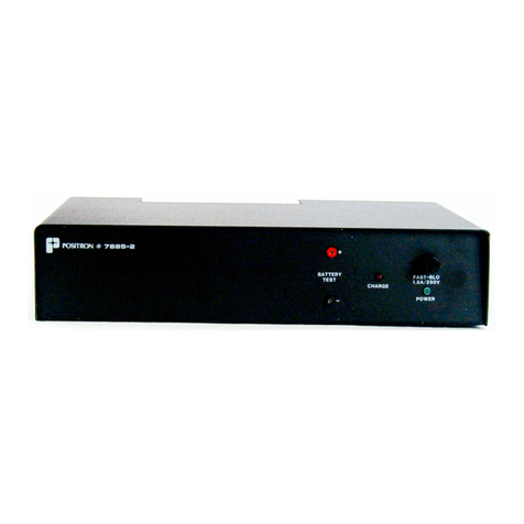
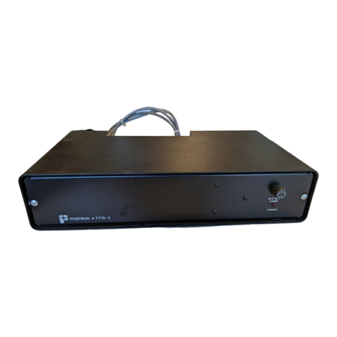
Positron Teleline 7715-24 Operating and installation instructions

Teleline™
Standalone Power Supply Unit
-129 Vdc to -24 Vdc (7715-24)
Description and Installation Guide
925W751005-01E


Contents
Chapter 1 – General Information
1.1 Publication Information . . . . . . . . . . . . . . . . . . . . . . . . . . . . . . . . . . . . . . . .4
1.2 About this Guide . . . . . . . . . . . . . . . . . . . . . . . . . . . . . . . . . . . . . . . . . . . . .5
Related Documentation. . . . . . . . . . . . . . . . . . . . . . . . . . . . . . . . . . . . . . 5
Positron Products and Services . . . . . . . . . . . . . . . . . . . . . . . . . . . . . . . 5
1.3 Service and Support . . . . . . . . . . . . . . . . . . . . . . . . . . . . . . . . . . . . . . . . . .6
Technical Customer Support. . . . . . . . . . . . . . . . . . . . . . . . . . . . . . . . . . 6
Customer Training. . . . . . . . . . . . . . . . . . . . . . . . . . . . . . . . . . . . . . . . . . 6
Repair Service. . . . . . . . . . . . . . . . . . . . . . . . . . . . . . . . . . . . . . . . . . . . . 7
1.4 Teleline Warranty . . . . . . . . . . . . . . . . . . . . . . . . . . . . . . . . . . . . . . . . . . . . .8
Limitation of Liability . . . . . . . . . . . . . . . . . . . . . . . . . . . . . . . . . . . . . . . . 8
Cancellation and Rescheduling Charges . . . . . . . . . . . . . . . . . . . . . . . . 9
Chapter 2 – Overview
2.1 The Standalone Power Supply Unit . . . . . . . . . . . . . . . . . . . . . . . . . . . . . .12
2.2 Features . . . . . . . . . . . . . . . . . . . . . . . . . . . . . . . . . . . . . . . . . . . . . . . . . . .13
2.3 Technical Specifications . . . . . . . . . . . . . . . . . . . . . . . . . . . . . . . . . . . . . .14
Chapter 3 – Installation
3.1 Installation . . . . . . . . . . . . . . . . . . . . . . . . . . . . . . . . . . . . . . . . . . . . . . . . .16
3.2 Mechanical Installation . . . . . . . . . . . . . . . . . . . . . . . . . . . . . . . . . . . . . . .18
Rack-mount. . . . . . . . . . . . . . . . . . . . . . . . . . . . . . . . . . . . . . . . . . . . . . 18
Wall-mount . . . . . . . . . . . . . . . . . . . . . . . . . . . . . . . . . . . . . . . . . . . . . . 18
3.3 Electrical Installation . . . . . . . . . . . . . . . . . . . . . . . . . . . . . . . . . . . . . . . . .19
Appendix A – Acronyms
A 1 Acronyms . . . . . . . . . . . . . . . . . . . . . . . . . . . . . . . . . . . . . . . . . . . . . . . . .24


Chapter 1
General Information

4
Standalone Power Supply Unit, Description and Installation Guide
1.1 Publication Information
© 2008 Positron Inc.
Teleline Standalone Power Supply Unit, -129 Vdc to -24 Vdc (7715-24),
Description and Installation Guide
Part number: 925-751005-01E
Publication date:
June 11, 2008
Published By
Positron Inc.
5101 Buchan Street, Suite 220
Montreal, Quebec, Canada
H4P 2R9
US and Canada: 1-888-577-5254
International: 1-514-345-2220
Trademarks
Teleline is a trademark of Positron Inc.
Product names, other than Positron’s, mentioned herein may be trademarks and/or registered
trademarks of their respective companies.
Confidentiality Notice
The information contained in this document is the property of Positron Inc. Except as specifically
authorized in writing by Positron Inc., the holder of this document: 1) shall keep all information
contained herein confidential and shall protect same in whole or in part from the disclosure and
dissemination to all third parties, and 2) shall use same for operating and maintenance purposes only.
Disclaimer Notice
Although Positron Inc. has made every effort to ensure the accuracy of the information contained
herein, this document is subject to change without notice.

5
About this Guide
1.2 About this Guide
This guide introduces you to the Teleline Standalone Power Supply Unit, its
features and applications, and describes how to install it in a Teleline shelf. This
guide was designed to be read from beginning to end.
1.2.1 Related Documentation
The other guides in the Teleline set are listed below. To order any manuals, please
contact your customer service representative.
QTeleline System Manual
QTeleline System Overview
QTeleline Product Guide
1.2.2 Positron Products and Services
Positron engineers and manufactures high voltage isolation products to protect
personnel and telecommunications circuits in high voltage areas that are
susceptible to the effects of Ground Potential Rise (GPR).
Positron is the leader in isolation technology with its Teleline wireline products and
TeleLite optical fiber wireline isolation/protection product families. Positron
provides total flexibility in product configuration – from standalone units protecting
a single circuit to high-capacity, multi-shelf HVI preconfigured systems.
Positron also provides a wide range of consulting, analysis and training services
for communications companies and electrical utilities.
Full details and contact information are available at www.PositronPower.com

6
Standalone Power Supply Unit, Description and Installation Guide
1.3 Service and Support
Table 1: Positron Contact Information
General information: Positron Inc.
5101 Buchan Street, Suite 220
Montreal, Quebec, Canada
H4P 2R9
US and Canada: 1-888-577-5254
International: 1-514-345-2220
Fax: 514-345-2271
E-mail: info@positronpower.com
Website: www.positronpower.com
Customer Service and
Repairs:
US and Canada: 1-888-577-5254
International: 1-514-345-2220
E-mail: customerservice@positronpower.com
1.3.1 Technical Customer Support
Positron is committed to providing excellent ongoing technical support to its
customers. A team of specialists is always available for telephone consultations or
for on-site visits to assist in the maintenance and troubleshooting of Positron
equipment.
For pricing information or assistance in the planning, configuration and
implementation of the installation of equipment, contact Technical Customer
Service.
1.3.2 Customer Training
Full customer training courses on High Voltage Interface (HVI) are also available.
For more information, contact Positron.

7
Service and Support
1.3.3 Repair Service
All warranty repairs are performed at no cost. Positron reserves the right to repair
or replace any equipment that has been found to be defective.
For information about out-of-warranty repairs, contact Positron’s Repair
Department. Due to the varied nature of repairs, no specific turnaround can be
guaranteed, but average turnaround time is 20 working days from date of receipt.
In emergency situations, special arrangements can be made. All repaired items
are warranted for a period of 90 days.
Before returning any items to Positron for repair, warranty repair or replacement,
call the Repair department to obtain a Return Material Authorization (RMA)
number. Parts returned without RMA numbers cannot be accepted. The RMA
number must always be clearly marked on all boxes, crates, and shipping
documents. Bulk repairs (more than five items) will require additional processing
time, so please take this into consideration when requesting an RMA number.
To accelerate the repair process, whenever possible, include a report detailing the
reason for return with the unit(s). Also, please include the name and phone
number of a person who can be contacted should our Repair department need
further information.
When packing items being returned for repair, please ensure they are properly
packed to avoid further damage. TeleLite plug-in cards should never be shipped
while installed in a shelf; this will cause damage that can extend the repair period.

8
Standalone Power Supply Unit, Description and Installation Guide
1.4 Teleline Warranty
Subject to the provisions of this paragraph, Positron warrants that the equipment
shall perform in accordance with Positron's specifications. The warranty remains
valid for five (5) years from the date of shipment. The warranty fully covers
workmanship, materials and labor. Positron shall, at its sole discretion, repair or
replace the problem unit.
Freight costs to ship defective equipment to Positron are borne by the Customer,
with return of replaced or repaired equipment to be at Positron's expense.
1.4.1 Limitation of Liability
Subject to anything to the contrary contained herein, Positron's sole obligation
and liability and the customer's sole remedy for Positron's negligence, breach of
warranty, breach of contract or for any other liability in any way connected with or
arising out of, the equipment or any services performed by Positron shall be as
follows:
QIn all situations involving performance or non-performance of the
equipment or any component thereof, the customer's sole remedy shall
be, at Positron's option, the repair or replacement of the equipment or
said component.
QFor any other claim in any other way related to the subject matter of any
order under, the customer shall be entitled to recover actual and direct
damages; provided that Positron's liability for damages for any cause
whatsoever, and regardless of the form of the action, whether in contract
or in tort (including negligence), shall be limited to the value of the order.
Positron shall not be obligated to repair or replace any item of the equipment
which has been repaired by others, abused or improperly handled, improperly
stored, altered or used with third party material or equipment, which material, or
equipment may be defective, of poor quality or incompatible with the equipment
supplied by Positron, and Positron shall not be obligated to repair or replace any
component of the equipment which has not been installed according to Positron
specifications.
IN NO EVENT SHALL POSITRON BE LIABLE FOR ANY INDIRECT,
INCIDENTAL, SPECIAL, CONSEQUENTIAL, PUNITIVE, EXEMPLARY OR
SIMILAR OR ADDITIONAL DAMAGES INCURRED OR SUFFERED INCLUDING

9
Teleline Warranty
LOSS OF PROFITS, LOSS OF REVENUES, LOSS OF DATA, LOSS OF
BUSINESS INFORMATION, LOSS OF GOODWILL, LOSS OF EXPECTED
SAVINGS OR BUSINESS INTERRUPTION ARISING OUT OF OR IN
CONNECTION WITH THE EQUIPMENT, A PURCHASE ORDER, SUPPLIES,
MAINTENANCE SERVICES OR OTHER SERVICES FURNISHED
HEREUNDER, EVEN IF POSITRON HAS BEEN ADVISED OR IS AWARE OF
THE POSSIBILITY OF SUCH DAMAGES.
EXCEPT AS EXPRESSLY SET FORTH IN THIS AGREEMENT, POSITRON
DISCLAIMS ANY FURTHER CONDITIONS, REPRESENTATIONS OR
WARRANTIES, WHETHER WRITTEN OR ORAL, EXPRESSED OR IMPLIED,
INCLUDING THE CONDITIONS AND WARRANTIES OF MERCHANTABILITY,
MERCHANTABLE QUALITY, FITNESS FOR A PARTICULAR PURPOSE, TITLE,
PERFORMANCE AND THOSE ARISING FROM STATUTE, TO THE EXTENT
PERMITTED BY LAW. POSITRON DOES NOT WARRANT THAT THE SYSTEM
WILL OPERATE WITHOUT INTERRUPTION OR THAT IT WILL BE ERROR
FREE.
1.4.2 Cancellation and Rescheduling Charges
Should the customer cancel, prior to shipment, any part of an order, the customer
agrees to pay to Positron cancellation charges, not as a penalty, which shall total
all expenses, including labor expenses, incurred by Positron prior to said
cancellation. Equipment that has been specially developed for the customer's
specific applications shall not be subject to cancellation. Cancellation or
rescheduling is not permissible after shipment of the System.


Chapter 2
Overview

12
Standalone Power Supply Unit, Description and Installation Guide
2.1 The Standalone Power Supply Unit
The Standalone power Supply Unit, model 7715-24 converts floating -129 Vdc
from a station battery to -24 Vdc referenced to station ground. This large capacity
standalone power supply may be used to power a fully loaded 3-, 5 or 8-card
Shelf.
The installation kit consists of the Standalone Power Supply Unit fixed on a
stainless steel, rack- or wall-mountable bracket and associated mounting
hardware.
Do not use Standalone Power Supply 7715-24 with the following
equipment:
QA shelf containing one or more -24 Vdc plug-in power supply cards such as:
751313, 751316 or 751324. (The -24 Vdc plug-in card in the shelf must be
permanently removed from the shelf if a standalone -24 Vdc supply is used)
QA shelf powered by any other -24 Vdc standalone power supply such as:
7715-2, 7715-3 or 7856-3
Figure 1: Model 7715-24 installed in its mounting bracket
N
OTE

13
Features
2.2 Features
Features of the Standalone Power Supply Unit, model 7715-24 include the
following:
QThe unit may be used with any old and new generation 3-, 5 or 8-card
Teleline Shelf.
QThe unit supplies continuous -24 Vdc up to 2 Amps from a -129 Vdc
floating station battery, without compromising its floating nature.
QThe power supply uses high-reliability, solid state switching technology to
perform the DC to DC conversion.
QThe power supply unit’s input is protected against overvoltage transients.
QTwo five-amp fast blow input fuses protect the power supply against
ground faults, and the station battery against a malfunction of the supply.
Both fuses are part of the terminal block.
QThe unit is equipped with a current limiting circuit at its input to prevent an
excessive current surge upon connection of the station battery.
QThe unit is equipped with a current limiter at the output for short circuit
protection.
QA green “Power Output” LED located on the front panel of the Standalone
Power Supply Unit indicates the presence of -24 Vdc output.

14
Standalone Power Supply Unit, Description and Installation Guide
2.3 Technical Specifications
Table 2: Electrical Specifications (measured at 77°F or 25°C)
Parameter Specification
Input station voltage -105 to -150 Vdc
Input power at full load 65 W
Nominal output voltage -24 Vdc
Maximum output current 2.0 A
Maximum output power 48 W
Output ripple voltage 100 mVpp
Regulation, line <1.0%
Regulation, load <5.0%
Input/output isolation 1500V @ 60 Hz for 1 minute
Table 3: Physical Specifications
Parameter Specification
Operating Temperature Range -40°F to 149°F (-40°C to 65°C)
Height 7” (17.8 cm)
Width 19” (48.3 cm)
Depth 3” (7.6 cm)
Weight 4.3 lbs (2 kg)

Chapter 3
Installation

16
Power Supply Unit, Description and Installation Guide
3.1 Installation
This installation procedure assumes that the associated 3-, 5 or 8-card Shelf
being used has already been mounted as per its installation instructions. For
further information, refer to the Description and Installation documentation for the
3-card Shelf, model 751127, 5-card Shelf, model 751112/1, or 8-card Shelf, model
751109/13.
QStand on a thick rubber mat and wear rubber gloves during the
installation procedure. It is preferable to perform these procedures on a
clear dry day when a Ground Potential Rise (GPR) or transients are
less likely to occur.
QThis unit utilizes CMOS circuitry that can be damaged by static
electricity. The unit is not to be opened.
C
AUTION

17
Installation
³To install the Standalone Power Supply Unit
1. Verify that you are not using any equipment which is incompatible with the
Standalone Power Supply Unit, model 7715-24. Do not use the Standalone
Power Supply Unit with any other plug-in or standalone -24 Vdc power supply.
Below is a listing of incompatible equipment.
Do not use Standalone Power Supply 7715-24 with the following
equipment:
QA shelf containing one or more -24 Vdc plug-in power supply cards such as:
751313, 751316 or 751324. (The -24 Vdc plug-in card in the shelf must be
permanently removed from the shelf if a standalone -24 Vdc supply is used)
QA shelf powered by any other -24 Vdc standalone power supply such as:
7715-2, 7715-3 or 7856-3
2. Verify that you have the following tools and hardware required to install the
unit:
QCenter punch
QElectric drill with a 5/32” diameter bit
Q7/16” hex wrench
QPhillips screwdriver
QCable clamps and mounting hardware for routing cables exterior to the
shelf (quantity determined by the cable lengths involved).
3. Unpack the Standalone Power Supply Unit and its installation hardware from
its protective box.
4. Check the contents of your Standalone Power Supply Unit kit. Below is a
listing of the items included in the kit.
Table 4: Model 7715-24 Kit Contents
Items Included Qty Part Number
Power Supply Module 1244W000010-401
Support bracket 1244W000009-401
5. Confirm that the unit is a Standalone power Supply Unit, model 7715-24 by
identifying the model number.
N
OTE

18
Power Supply Unit, Description and Installation Guide
3.2 Mechanical Installation
The Standalone Power Supply Unit can be installed on a 19” rack or on a wall.
3.2.1 Rack-mount
³To install the Standalone Power Supply Unit in an equipment rack
1. Position the support bracket on the rack and fasten using bolts.
2. Install the power converter.
3.2.2 Wall-mount
³To install the Standalone Power Supply Unit using a wall-mount
1. Fasten the support bracket to the wall using four screws.
2. Install the power supply.
Figure 2: Model 7715-24 Installation
Table of contents
Other Positron Power Supply manuals