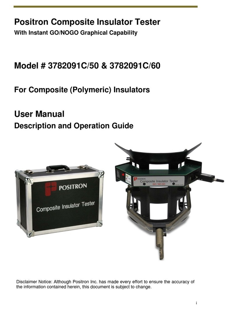
Positron 3782101C/50 User manual

i
Positron Composite Insulator Tester
Model # 3782101C/50 & 3782101C/60
Composite (Polymeric) Insulator Tester
For 25kV Electric Railway Systems
User Manual
Description and Operation Guide
Disclaimer Notice: Although Positron Inc. has made every effort to ensure the accuracy of
the information contained herein, this document is subject to change.


CAUTION
IMPORTANT SAFETY NOTICE
This instrument is intended to be used in high voltage environments.
It should be used ONLY by personnel trained to work in those environments.
Although this instrument does not make electrical contact with the high voltages,
IT IS ESSENTIAL THAT THIS INSTRUMENT IS USED COUPLED WITH A SUITABLE
HIGH DIELECTRIC STRENGTH HOT STICK THAT HAS A VOLTAGE RATING
EQUIVALENT TO OR GREATER THAN THE VOLTAGE ON THE DEVICES OR LINES
BEING TESTED.
NOTE
To be used on AC lines only


Contents
ii
Contents
1.0 General Information .........................................................................................................3
1.1 Publication Information.............................................................................................................. 3
1.2 About this Guide ........................................................................................................................ 3
1.3 How to use this Guide ................................................................................................................ 4
1.4 List of Associated References ..................................................................................................... 4
2.0 Introduction to the Composite Insulator Testers ................................................................7
2.1 Personnel Terminology Used in this Guide ................................................................................. 7
2.2 General....................................................................................................................................... 7
2.2.1 Recommended Testing Methodology:........................................................................................ 8
2.2.2 Advantages of Using Positron Testers (PID)................................................................................ 8
2.3 Overview ................................................................................................................................... 9
2.4 Composite Insulator Tester Model Numbers ............................................................................ 10
3.0 Description of Composite (Polymeric) Insulator Tester Kit................................................13
3.1 The Composite Tester Kit.......................................................................................................... 13
3.2 Tester Charger .......................................................................................................................... 14
3.3 Insulator Tester Sled................................................................................................................. 14
3.4 Sled Adjustments ..................................................................................................................... 15
3.5 Placement of Probe on the Insulator Sled................................................................................. 15
3.6 Tablet/Laptop........................................................................................................................... 16
3.6.1 General .................................................................................................................................... 16
3.6.2 Separating the Tablet while in the Field ................................................................................... 16
4.0 Windows-based Insulator Tester Software.......................................................................21
4.1 Insulator Tester Software Description ...................................................................................... 21
4.2 The Bluetooth Serial Adaptor ................................................................................................... 22
4.3 Instant Graphical GO/NO-GO Reporting Capability .................................................................. 22
5.0 Using the Composite Insulator Tester & Software ............................................................25
5.1 BEFORE Testing Sessions .......................................................................................................... 25
5.1.1 Select the Default Folder.......................................................................................................... 25
5.1.2 Changing the Folder ................................................................................................................. 26
5.1.3 Create a List of Insulator Identifications ................................................................................... 26
5.1.4 Verifying Communication Before a Testing Session.................................................................. 28
5.1.5 Switching the Probe On............................................................................................................ 28
5.1.5.1 Power-On Self-Test (POST) of the Insulator Tester................................................................29
5.1.6 Check Long-Range Bluetooth Serial Port Communication ........................................................ 30
5.1.7 Get (Software) Revision of the Probe ....................................................................................... 32

Contents
iii
5.2 DURING Testing Sessions.......................................................................................................... 33
5.2.1 Scanning a 25kV Composite (Polymeric) Railway-Insulator ...................................................... 35
5.2.1.1 Performing a Horizontal Scan of a Insulator ..........................................................................35
5.2.1.2 Performing an Angular Scan ..................................................................................................36
5.2.1.3 Performing a Vertical Scan.....................................................................................................37
5.2.2 Downloading Data ................................................................................................................... 38
5.3 Using the Tester without the Tablet and Bluetooth.................................................................. 42
5.4 AFTER Testing Sessions............................................................................................................. 46
5.4.1 Displaying Graphs .................................................................................................................... 46
5.4.2 Searching the Database............................................................................................................ 46
5.5 Important General Notes.......................................................................................................... 47
6.0 Interpreting Graphed Results ..........................................................................................51
6.1 Understanding the Graphs ....................................................................................................... 51
6.2 Linear and Log Graph Options .................................................................................................. 52
6.3Using the COMPARE function to Compare Historical Graphs .................................................... 53
6.4Composite Insulator Tester Results: Healthy Insulators............................................................ 54
6.4.1 Creating a Reference Graph of a Known-Good, Clean Insulator................................................ 54
6.4.2 Defects..................................................................................................................................... 55
6.4.3 Floating Defects ....................................................................................................................... 57
7.0 Specifications..................................................................................................................61
8.0 Important Information....................................................................................................65
8.1 Service and Support ................................................................................................................. 65
8.2 Technical Customer Support..................................................................................................... 65
8.3 Customer Training .................................................................................................................... 65
8.4 Repair Service........................................................................................................................... 65
8.5 Warranty .................................................................................................................................. 66
8.6 Limitation of Liability................................................................................................................ 66
8.7 Disclaimer Notice ..................................................................................................................... 67
8.8 Cancellation and Rescheduling Charges.................................................................................... 67

1
Chapter 1
General Information

General Information
2

General Information
3
1.0 General Information
1.1 Publication Information
© 2018 Positron Inc.
Positron Composite Insulator Tester
Description and Operation Guide
User Manual Part #: 925W378210-02E
(Based on Part # 925W378209-09E)
Publication date: December 2018
Published By
Positron Inc.
5101 Buchan Street, suite 220
Montréal, Québec
H4P 2R9 Canada
Trademarks
Positron Insulator Tester is a trademark of Positron Inc.
The Insulator Testers are manufactured by Positron Inc. in Montreal, Canada. The Positron
Insulator Testers is protected by US patents including “METHOD AND APPARATUS FOR THE
VERIFICATION OF AN ELECTRICAL INSULATOR DEVICE BASED ON THE ANALYSIS OF THE
ELECTRICAL FIELD ALONG THE INSULATOR”.
Product names, other than Positron’s, mentioned herein may be trademarks and/or registered
trademarks of their respective companies.
Confidentiality Notice
The information contained in this document is the property of Positron Inc. Except as specifically
authorized in writing by Positron Inc., the holder of this document:
1) shall keep all information contained herein confidential and shall protect same in whole or
in part from the disclosure and dissemination to all third parties, and
2) shall use same for operating and maintenance purposes only.
1.2 About this Guide
This guide introduces you to and describes the operation of Positron’s Live Line High Voltage
Tester used as a maintenance tool to test and report defects in Composite Insulators and for use
as a safety tool to determine the condition of high-voltage insulators prior to beginning Live-
Power Line work.

General Information
4
1.3 How to use this Guide
This guide was designed to describe the operational modes of the Composite Insulator Testers:
The reader is invited to use the digital (PDF) version of this document to allow searching by
keywords. Select Edit, then Find from the pull-down menu, or select Ctrl+F to access the Find
menu.
1.4 List of Associated References
[1] “Suspension Insulator Puncture Insulator Tester”; Report No. ELE 92-62; Bonneville Power Administration Division of
Laboratories; December 7, 1992.
[2] G.H. Vaillancourt, J.P. Bellerive, M. St-Jean, C. Jean, “New Live Line Insulator Tester for Porcelain Insulators on High-Voltage
Power Line,” IEEE Transactions on Power Delivery, Vol. 9, January 1994, pp. 208-219.
[3] “J.C. Pohlman, C.R. Davis, “Cracked Insulators Create Hazardous Working Conditions During Restoration after Extreme Ice
Storms,” Proceedings of ESMO-95, Columbus, Ohio, USA, October 29 - November 3, 1995, IEEE Paper 95CH35755.
[4] A.S. Jagtiani, J.R. Booker, “Aging of Porcelain Insulators Under Mechanical and Electrical Stress on EHV AC Lines,” Proceedings of
ESMO-95, Columbus, Ohio, USA, October 29 - November 3, 1995, IEEE Paper ESMO 95-CP-08.
[5] G. H. Vaillancourt, M. Hamel, J. Frate, “Experience with Two Faulty Composite Insulators Detection Methods in Hydro-Quebec,”
Conference Proceedings of 10th International Symposium on High Voltage Engineering, Montreal, Canada, August 25-29, 1997.
[6] G. H. Vaillancourt, P. Bilodeau, “Diagnostic Testing of Composite Insulators Used on Series Compensation Platforms in Hydro-
Quebec,” Conference Proceedings of 11th International Symposium on High Voltage Engineering, London, England, August 22-27,
1999.
[7] G. H. Vaillancourt, S. Carignan, C. Jean, “Experience with the detection of faulty composite insulators on High-Voltage power lines
by the E-field measurement method,” IEEE Transactions on Power Delivery, Val. 13, No. 2, April 1998, pp 661-666.
[8] Y.C. Chen, C. R. Li, X. Liang, S. Wang, “The Influence of Water and Pollution on Diagnosing Defective Composite Insulators by E-
field Mapping,” Conference Proceedings of 11th International Symposium on High Voltage Engineering, London, England, August 22-
27, 1999.
[9] D. H. Shaffner, D. L. Ruff, G. H. Vaillancourt, “Experience with a Composite Insulator Testing Instrument based on the Electric
Field method” ESMO 2000, Montreal, Canada, October 8-12, 2000.
[10] L. J. Fernandez, J. M. Munoz, A. Andrés, "Electric field measurement on composite insulators using live working techniques", 5th
International Conference on Live Maintenance, ICOLIM 2000, Madrid, Spain, May 17-19, 2000.
[11] I. Gutman (SE), A. Pigini (IT) et al. "Assessment of Composite Insulators by means of Online Diagnosis", CIGRE WG B2.21 2013.
[12] C. Jean, "High Voltage Insulator Testing based on Electric Field method" 2015 INMR World Congress Conference, Munich,
Germany, September 2015.

5
Chapter 2
Overview

Overview
6

Overview
7
2.0 Introduction to the Composite Insulator Testers
2.1 Personnel Terminology Used in this Guide
The Composite Insulator Tester is used by field technicians and are referred to in this document
as the “Tester Operator”.
The Foreman or other members of the supporting Crew operate the Tablet/Laptop used in the
field together with the Insulator Tester. In this guide they are referred to as the “Tablet
Operator”.
2.2 General
The document describes the operation of Positron’s Composite Insulator Tester.
Model # 3782101C/50: Composite Insulator Tester, 50Hz
Model # 3782101C/60: Composite Insulator Tester, 60Hz
Refer to Figure 1 for a detailed drawing of the unit.
With the Composite Insulator Tester Probe mounted onto a user-supplied hot-stick, the Tester
Operator passes the Probe along the length of the composite Insulator. Any conductive defect in
an insulator will cause a change in the E-Field surrounding the insulator. This perturbation of the
E-Field indicates a faulty insulator. The fault is detected and identified by the Probe, and the
data is downloaded to a database installed on the Tablet/PC for analysis. The graph displaying
the E-Field of the insulator is clearly displayed on the Tablet/Laptop while in the field enabling
GO/NOGO decision-making on-the-spot.
The skirts, or sheds, of Polymeric or Composite insulators are counted by the field Probe’s two
integrated infrared detectors, referred to as IR1 and IR2 (see Figure 1), and the E-Field of each
insulator is recorded. Defective insulators are easily identified using the resulting data graphs
that present the contour of the E-Field along the length of the composite insulator. The field
Probe contains a microprocessor-based recording system. A minimum of 5 skirts is required for
a scan.
After a Composite insulator is scanned by the Tester Operator, the Tablet Operator downloads
the Probe’s data via a long range Bluetooth communication link to the Tablet/Laptop for
immediate GO/NOGO analysis.
The data is stored in ASCII format in order to be compatible with any text editor, including Excel
spreadsheet and Microsoft NOTEPAD, plus the ASCII data can be imported into existing
customer databases.
Verify the Date and Time settings of the Tablet/Laptop
It is important to disable the WIFI of the Tablet/Laptop to avoid long operating system
updates and interference with the long range Bluetooth communication link while preparing
for or performing a testing session.
NOTE

Overview
8
2.2.1 Recommended Testing Methodology:
Testing insulators when dry using the Positron testers will only detect conductive defects in the
insulators. Testing the insulators when moist, the Positron testers will detect defects in the
insulators as well as conductive defects due to pollution.
When a flashover occurs in a region, it is prudent to test not only the flashed over insulator, but
also other insulators in that area. The likelihood is that if one insulator flashed over, other
adjacent or nearby insulators will be similarly covered by a pollutant film and should be tested
as they are also likely to flash over in the near future when moistened by rain or early morning
dew.
If the railway operator gets readings on many insulators in a region that show high conductive
pollution on insulators, the railway operator will know which groups of insulators should be
changed or cleaned at one time as a preventative maintenance measure. This minimizes
interruptions or downtime of rail traffic as well as minimizing danger to any maintenance crew
whether working underneath the high-voltage lines per their routine schedule. The Tester will
act as a Health detector of the insulators tested in advance of any failure.
Whether or not the insulators are cleaned, the Positron Tester will detect conductive defects
whether due to an internal defect in the insulator or due to surface pollution conductive defects
under moist conditions. It is possible to test segments of the electrified insulators along a line to
determine if they are defective, or if they will flashover due to pollution accumulation.
2.2.2 Advantages of Using Positron Testers (PID)
Health detection of overhead insulators in advance of any failures;
Enables the use of a defined maintenance schedule;
Safety of maintenance crews and other personnel doing proximity works;
Detects all internal insulator conductive defects;
Detects defects due to surface contamination (moist conditions may be required to
detect certain defects);
Prevents outages and railway traffic delays;
Reduces time to find defects and to perform appropriate maintenance;
Reduces costs (for maintenance and operation of the railway traffic).

Overview
9
2.3 Overview
Model #3782101C/xx
Figure 1: Composite Insulator Tester (C-Tester) Model #s
3782101C/50 (50Hz) & 3782101C/60 (60Hz)

Overview
10
2.4 Composite Insulator Tester Model Numbers
For ordering information, contact Positron Customer Support:
North America: 1-888-577-5254, Option 9, Option 1.
International: 001-514-345-2220, Option 9, Option 1
Testers and Model Numbers
Item Description
Model
Number
Composite Railway Insulator tester, 60 Hz, standard 10” sled
3782101C/60
Composite Railway Insulator tester, 50 Hz, standard 10” sled
3782101C/50
220Vac/120Vac cable charger replacement
378126
Rechargeable battery pack replacement for the Probe
378127
12Vdc auxiliary automotive power cable charger replacement
378128
RS232 Long-range Bluetooth adapter replacement
378325/3
Replacement standard sled kit for 378210/xx
378610
50 Hz GO/NO-GO E-field Probe for Composite Insulators (no sled)
378608
60 Hz GO/NO-GO E-field Probe for Composite Insulators (no sled)
378612
Replacement cover plate for Probe power switch (Min Order 25 pcs)
378613
Figure 3

11
Chapter 3
Composite Insulator Tester Elements

Composite Insulator Tester Elements
12

Composite Insulator Tester Elements
13
3.0 Description of Composite (Polymeric) Insulator Tester Kit
3.1 The Composite Tester Kit
The Composite Tester kit consists of:
User manual
A Quick Start Guide
A rugged carrying case
An adjustable Composite (Polymeric) Insulator Tester Sled
USB key loaded with Insulator Tester user manual and PC software installer
A 12Vdc auxiliary automotive power cable charger
Sled spacer set to accommodate various insulator sizes
A long-range RS232 Bluetooth Serial Adaptor, pre-paired with the Tablet/Laptop
A Tablet/Laptop with Insulator Tester Data Processing Software installed
Plug-in wall transformer: 120Vac/220Vac input, 12Vdc output (includes international wall-
plug adaptors)
Spare switch cover
The Tester Operator Interface (see Figure 2) consists of:
a push-button
a Status LED
An ON/OFF switch is located to the left of the RS-232 connector underneath the Power Switch
Cover. Remove the Power Switch Cover and slide the switch to the right to switch the Insulator
Tester on. Slide the switch toward the left to switch the Insulator Tester off. See Figure 3.
DO NOT TURN THE POWER SWITCH OFF BEFORE DOWNLOADING THE DATA.
When the power is turned off the accumulated data in the Probe is lost.
Figure 2
Location of Power Switch Cover
Power Switch Cover
Power Switch
(OFF position)
Figure 3

Composite Insulator Tester Elements
14
The Insulator Tester uses two infrared detectors to
find the location of each E-Field reading. Please
refer to Figure 4. The two infrared detectors are
identified as IR1 and IR2.
The RS232 connector port is used to recharge the
Probe’s battery and to connect a Bluetooth dongle
for data transfer.
3.2 Tester Charger
The Insulator Tester’s battery is recharged using a 120Vac/220Vac universal wall charger
connected to a cable with a DB-9, RS232 female connector to connect to the Insulator Tester. A
set of AC charger adaptors is provided to accommodate various country standards. For charging
the Insulator Tester in the field, a 12Vdc auxiliary automotive charger cable terminated in a DB-9
connector is supplied to recharge the battery from a car or truck.
Both the AC power charger and the automotive DC charger are equipped with an LED status to
report on the charging status. When first plugged in to charge, the LED will glow red. After 9
hours on charge, the LED will glow green, indicating that the charging time is completed.
The battery should be recharged overnight the day before a testing session. The battery charge
will last one day with the power switch in the ON position.
The battery can be recharged with the power switch in the ON or OFF position, however the
Insulator Tester will charge faster when switched off.
The data accumulated by the Insulator Tester must be transferred via Bluetooth to a
Tablet/Laptop prior to switching the Insulator Tester off or the data will be lost.
3.3 Insulator Tester Sled
The Insulator Tester mounts on a non-metallic sled. The sled permits the Insulator Tester to
slide along an insulator string.
Together, the sled and Insulator Tester attach to a hot stick via the coupler mounted on the
sled’s bracket. See Figure 5.
Figure 4
NOTE
Insulator Tester Sled Hot stick Coupler
Figure 5
Insulator Sled for
#3782101C/x
This manual suits for next models
1
Table of contents
Other Positron Test Equipment manuals