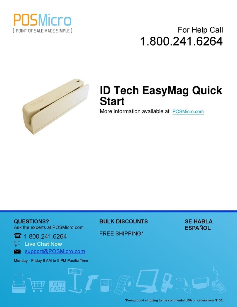
POSMicro ID Tech MiniMag User manual

QUESTIONS?
Ask the experts at POSMicro.com.
1.800.241.6264
Live Chat Now
Monday - Friday 6 AM to 5 PM Pacic Time
BULK DISCOUNTS
FREE SHIPPING*
SE HABLA
ESPAñOL
*Free ground shipping to the continental USA on orders over $100.
For Help Call
1.800.241.6264
ID Tech MiniMag
Manual
More information available at POSMicro.com

MiniMag & EasyMag USB HID Reader Interface Reference
USER MANUAL
MINIMAG & EASYMAG
USB HID READERS
Models IDMB & IDEA
INTERFACE REFERENCE
02/02/2006
80066510-003
Rev. A; R02/06
#412
Copyright © 2006, International Technologies & Systems Corporation. All rights reserved.
Page 1 of 15

MiniMag & EasyMag USB HID Reader Interface Reference
Copyright © 2006, International Technologies & Systems Corporation. All rights reserved.
Page 2 of 15
FCC WARNING STATEMENT
This equipment has been tested and found to comply with the limits for a Class B digital device,
pursuant to Part 15 of FCC Rules. These limits are designed to provide reasonable protection
against harmful interference when the equipment is operated in a commercial environment. This
equipment generates, uses, and can radiate radio frequency energy and, if not installed and used
in accordance with the instruction manual, may cause harmful interference to radio
communications. Operation of this equipment in a residential area is likely to cause harmful
interference in which case the user will be required to correct the interference at his expense.
FCC COMPLIANCE STATEMENT
This reader complies with Part 15 of the FCC Rules. Operation of this reader is subject to the
following conditions: this reader may not cause harmful interference and this reader must accept
any interference received, including interference that may cause undesired operation.
CE STANDARDS
An independent laboratory performed testing for compliance to CE requirements. The unit under
test was found compliant to Class B.

MiniMag & EasyMag USB HID Reader Interface Reference
LIMITED WARRANTY
ID TECH warrants to the original purchaser for a period of 24 months from the date of invoice that
this product is in good working order and free from defects in material and workmanship under
normal use and service. ID TECH’s obligation under this warranty is limited to, at its option,
replacing, repairing, or giving credit for any product which has, within the warranty period, been
returned to the factory of origin, transportation charges and insurance prepaid, and which is, after
examination, disclosed to ID TECH’s satisfaction to be thus defective. The expense of removal
and reinstallation of any item or items of equipment is not included in this warranty. No person,
firm, or corporation is authorized to assume for ID TECH any other liabilities in connection with the
sales of any product. In no event shall ID TECH be liable for any special, incidental or
consequential damages to Purchaser or any third party caused by any defective item of
equipment, whether that defect is warranted against or not. Purchaser’s sole and exclusive
remedy for defective equipment, which does not conform to the requirements of sales, is to have
such equipment replaced or repaired by ID TECH. For limited warranty service during the
warranty period, please contact ID TECH to obtain a Return Material Authorization (RMA) number
& instructions for returning the product.
THIS WARRANTY IS IN LIEU OF ALL OTHER WARRANTIES OF MERCHANTABILITY OR
FITNESS FOR PARTICULAR PURPOSE. THERE ARE NO OTHER WARRANTIES OR
GUARANTEES, EXPRESS OR IMPLIED, OTHER THAN THOSE HEREIN STATED. THIS
PRODUCT IS SOLD AS IS. IN NO EVENT SHALL ID TECH BE LIABLE FOR CLAIMS BASED
UPON BREACH OF EXPRESS OR IMPLIED WARRANTY OF NEGLIGENCE OF ANY OTHER
DAMAGES WHETHER DIRECT, IMMEDIATE, FORESEEABLE, CONSEQUENTIAL OR
SPECIAL OR FOR ANY EXPENSE INCURRED BY REASON OF THE USE OR MISUSE, SALE
OR FABRICATIONS OF PRODUCTS WHICH DO NOT CONFORM TO THE TERMS AND
CONDITIONS OF THE CONTRACT.
The information contained herein is provided to the user as a convenience. While every effort has
been made to ensure accuracy, ID TECH assumes no responsibility, for its use, nor for any
infringements or patents or other rights of third parties that may result from its use. ID TECH is
not responsible for damages that might occur because of errors or omissions, including any loss
of profit or other commercial damage. The specifications described herein were current at the
time of publication, but are subject to change at any time without prior notice.
ID TECH is a registered trademark of International Technologies & Systems Corporation.
Spectrum and Value through Innovation are trademarks of International Technologies & Systems
Corporation.
ID TECH
10721 Walker Street
Cypress, CA 90630
(714) 761-6368
ISO 9001-2000
Copyright © 2006, International Technologies & Systems Corporation. All rights reserved.
Page 3 of 15

MiniMag USB HID Reader Interface Reference
TABLE OF CONTENTS
1. Introduction...........................................................................................................................5
2. Features and Specifications................................................................................................5
3. Installation.............................................................................................................................6
3.1 UBC Connection.....................................................................................................................6
3.2 Windows Plug and Play Setup ...............................................................................................6
4. Operation...............................................................................................................................7
4.1 LED Indicator..........................................................................................................................7
4.2 Card Reading .........................................................................................................................7
5. USB HID Interface.................................................................................................................8
5.1 Data Structure ........................................................................................................................8
5.2 ID TECH Format Data Structure.............................................................................................9
5.3 Mag-Tek Format Data Structure.............................................................................................9
5.4 IDTECH format and MagTek format.....................................................................................10
5.5 Descriptor Tables .................................................................................................................10
Device Descriptor.......................................................................................................................10
Configuration Descriptor.............................................................................................................11
Interface Descriptor....................................................................................................................11
HID Descriptor............................................................................................................................11
End Pointer Descriptor...............................................................................................................12
Report Descriptor, (ID TECH Setting)........................................................................................12
Report Descriptor, (MagTek Setting) .........................................................................................13
6. HID Usages..........................................................................................................................14
6.1 IDTECH format reader usage page 0xff00...........................................................................14
6.2 Mag-Tek format reader usage page 0xff00.........................................................................15
7. Commands and responses................................................................................................15
Copyright © 2006, International Technologies & Systems Corporation. All rights reserved.
Page 4 of 15

MiniMag USB HID Reader Interface Reference
1. Introduction
The MiniMag USB HID Reader is a magstripe card reader that conforms to ISO
standards. The reader is compatible with personal computers or a device with a
USB interface. A LED (Light Emitting Diode) and a beeper on the reader provide
status of the reading operations.
The reader conforms to the USB Human Interface Device (HID) Class specification
Version 2.0. Host applications designed for the latest versions of Windows 98, Me,
2000, XP can easily communicate to the reader using standard Windows API calls.
The reader is a “vendor defined HID device” so that a direct communication path
can be established with an application.
A demo program with its source code is available, written in Visual Basic, and
exercises the reader using the standard Windows API.
2. Features and Specifications
• Powered through the USB – no external power supply
• Hardware Compatible with PC or terminal with a USB interface
• Reads encoded data that meets ANSI/ISO/CDL/AAMVA standards
• Reads up to three tracks of card data
• Bi-directional card reading LED for status
• Compatible with USB specification Revision 2.0
• Compatible with HID specification Version 2.0
• Can use standard Windows HID driver for communications.
• Programmable USB Interrupt in Endpoint polling interval
• Non-volatile flash EEPROM memory for reader configuration storage
• Built-in 6 foot USB cable
Copyright © 2006, International Technologies & Systems Corporation. All rights reserved.
Page 5 of 15

MiniMag USB HID Reader Interface Reference
3. Installation
This section describes the cable connection and the Windows Plug & Play Setup.
3.1 UBC Connection
Connect the reader USB cable to a host USB port. The LED Indicator will light
green. For Reference, the pin numbers for the 4-pin USB connector are shown
in Figure 2-1.
Figure 2-1. Reader Cable and Connector
4-Pin Connector
Pin Number Signal Cable Color
1 VCC Red
2 - Data White
3 +Data Green
4 Ground Black
3.2 Windows Plug and Play Setup
The first time the device is plugged into a specific USB port, Windows will pop up
a dialog box. The box provides a guide through the process of installing the HID
device driver. After this process is completed once, Windows will no longer
request this process as long as the device is plugged into the same USB port.
The device driver that Windows will install for this device is the driver used for
HID devices and it is part of the Windows operating system. Most Windows will
find all the files it needs on its own without giving you any prompts. Other times
Windows will need to know the location of the files it needs.
Copyright © 2006, International Technologies & Systems Corporation. All rights reserved.
Page 6 of 15

MiniMag USB HID Reader Interface Reference
4. Operation
This section describes the LED Indicator and Card Reading.
4.1 LED Indicator
The LED indicator will be either red, or green. The LED is green when the device
is powered. When the device is first plugged in, the LED will be amble. As soon
as the device is plugged in, the host will try to enumerate the device. Once the
device is enumerated the LED will turn green indicating that the device is ready
for use. When a card is being swiped, the LED will turn off temporarily until the
swipe is completed. If there are no errors decoding the card data then the LED
will turn green. If there are any errors decoding the card data, the LED will turn
red for less than one second to indicate that an error occurred and then turn
green. The reader does support USB suspend mode; the LED be off in suspend
mode.
4.2 Card Reading
A card may be swiped through the reader slot when the LED is green. The
magnetic stripe must face toward the magnetic read head and may be swiped in
either direction. The data encoded on the card will be decoded and the data
transmitted and accepted into the USB HID input report. The reader LED will be
off during the data transfer and is ready to read another card when the LED
returns to green. A red LED indicates an error and the beeper will also provide
error indications. The beeper will beep for each correctly read track of data on
the magstripe card.
Copyright © 2006, International Technologies & Systems Corporation. All rights reserved.
Page 7 of 15

MiniMag USB HID Reader Interface Reference
5. USB HID Interface
The MiniMag reader conforms to the USB specification revision 2.0. This device
also conforms to the Human Interface Device (HID) class specification version 2.0.
The reader communicates to the host as a vendor defined HID device. The details
about how the card data and commands are structured into HID reports follow later
in this section. The latest versions of the Windows operating systems, Windows 98,
Me, 2000, and XP all come with a standard Windows USB HID driver. Windows
applications that communicate to this reader can be easily developed. These
applications can communicate to the reader using standard windows API calls that
communicate to the reader using the standard Windows USB HID driver. These
applications can be easily developed using compilers such as Microsoft’s Visual
Basic or Visual C++. A demonstration program and its source code, written in
Visual Basic, that communicates with this reader is available. This demo program
can be used to test the reader and it can be used as a guide for developing other
applications. More details about the demo program follow later in this document.
Developers should become familiar with the HID specification and the USB
specification before attempting to communicate with the reader. This document
assumes the developer is familiar with these specifications. Specifications can be
downloaded free from www.usb.org.
This is a full speed USB reader. The reader has a number of programmable
configuration properties. These properties are stored in non-volatile EEPROM
memory. These properties can be configured at the factory or by the end user. The
reader has an adjustable endpoint descriptor polling interval value that can be set
to any value in the range of 1ms to 255ms. This property can be used to change
the speed of the card data transfer rate.
5.1 Data Structure
MiniMag USB HID Reader supports both Mag-Tek and ID TECH data Structure
with an EEPROM setting.
USB HID Data Format Setting:
Setting A: ID TECH Data Format (Default setting) Product ID: 0500
Setting B: MagTek Data Format Product ID: 0510
During first time the reader is plugged in, the Firmware will read the "Data Format
Setting" from EEPROM and send current Product ID in enumeration. Each time
after changing the "Data Format Setting", the firmware will save the setting to
EEPROM then re-do the enumeration process. (On occasion, the reader will need
to be disconnected and connected again to switch the data format.)
Copyright © 2006, International Technologies & Systems Corporation. All rights reserved.
Page 8 of 15

MiniMag USB HID Reader Interface Reference
5.2 ID TECH Format Data Structure
Offset Usage Name .
0 T1 decode status
1 T2 decode status
2 T3 decode status
3 T1 data length
4 T2 data length
5 T3 data length
6 Card encode type
7, 8 Total Output Length
9-508 Output Data
In this approach, the reader will keep all of the ID TECH data editing and
other features like preamble, postamble, etc. The output data is always 500
bytes; the "Total Output Length" field indicates the valid data length in the
output data.
5.3 Mag-Tek Format Data Structure
Offset Usage Name .
0 T1 decode status
1 T2 decode status
2 T3 decode status
3 T1 data length
4 T2 data length
5 T3 data length
6 Card encode type
7-116 T1 data
117-226 T2 data
227-336 T3 data
Copyright © 2006, International Technologies & Systems Corporation. All rights reserved.
Page 9 of 15

MiniMag USB HID Reader Interface Reference
5.4 IDTECH format and MagTek format
T1, T2 or T3 decode status: 0 for no error, 1 for error
T1, T2 or T3 Data Length: Each byte value indicates how many bytes of decoded
card data are in the track data field. This value will be zero if there was no data on
the track or if there was an error decoding the track. The track data includes all
data string starting with the start sentinel and ending with the end sentinel.
Card Encode Type:
Value Encode TypeDescription
0 ISO/ABA ISO/ABA encode format
1 AAMVA AAMVA encode format
2 CADL California Driver License
3 Blank The card is blank
4 Other The card has a non-standard format.
For example, ISO/ABA track 1 format on track 2
5.5 Descriptor Tables
Device Descriptor
Field Value Description
Length 12
Des type 01
bcd USB 10 01
Device Class 03
Sub Class 00 Unused
Device Protocol 00 Unused
Max Packet Size 20 32 bytes
VID CD 0A
PID 00 05
/ 10 05 With ID TECH Structure
With MagTech Structure
BCD Device Release 00 01
i-Manufacture 01
i-Product 02
i-Serial-Number 00
# Configuration 01
Copyright © 2006, International Technologies & Systems Corporation. All rights reserved.
Page 10 of 15

MiniMag USB HID Reader Interface Reference
Configuration Descriptor
Field Value Description
Length 09
Des type 02
Total Length 22 00
No. Interface 01
Configuration Value 01
iConfiguration 00
Attributes 80 Bus power, no remove wakeup
Power 32 100 mA
Interface Descriptor
Field Value Description
Length 09
Des type 04
Interface No. 00
Alternator Setting 00
# EP 01
Interface Class 03 HID
Sub Class 00
Interface Protocol 00
iInterface 00
HID Descriptor
Field Value Description
Length 09
Des type 21 HID
bcdHID 11 01
Control Code 00
numDescriptors 01 Number of Class Descriptors to follow
DescriptorType 22 Report Descriptor
37 00 For ID TECH FormatDescriptor Length 3D 00 For MagTek Format
Copyright © 2006, International Technologies & Systems Corporation. All rights reserved.
Page 11 of 15

MiniMag USB HID Reader Interface Reference
End Pointer Descriptor
Field Value Description
Length 07
Des Type 05 End Point
EP Addr 81 EP1 - In
Attributes 03 Interrupt
MaxPacketSize 20 00
bInterval 0A
Report Descriptor, (ID TECH Setting)
Field Value Description
06 00
FF Usage Page (MSR)
09 01 Usage(Decoding Reader)
A1 01 Collection (Application)
15 00 Logical Minimum
26 FF
00 Logical Maximum
75 08 Report Size
09 20 Usage (Tk1 Decode Status)
09 21 Usage (Tk2 Decode Status)
09 22 Usage (Tk3 Decode Status)
09 28 Usage (Tk1 Data Length)
09 29 Usage (Tk2 Data Length)
09 2A Usage (Tk3 Data Length)
09 38 Usage (Card Encode Type)
95 07 Report Count
81 02 Input (Data,Var,Abs,Bit Field)
09 30 Usage (Total Sending Length)
95 02 Report Count (2)
82 02
01 Input (Data, Var, Abs, Bit Field)
09 31 Usage (Output Data)
96 F4
01 Report Count (328*)
82 02
01 Input (Data, Var, Abs, Bit Field)
09 20 Usage (Command Message)
95 20 Report Count
B2 02
01 Feature (Data,Var, Abs, Buffered Bytes)
C0 End Collection
Copyright © 2006, International Technologies & Systems Corporation. All rights reserved.
Page 12 of 15

MiniMag USB HID Reader Interface Reference
Report Descriptor, (MagTek Setting)
Field Value Description
06 00
FF Usage Page (MSR)
09 01 Usage(Decoding Reader)
A1 01 Collection (Application)
15 00 Logical Minimum
25 FF
00 Logical Maximum
75 08 Report Size
09 20 Usage (Tk1 Decode Status)
09 21 Usage (Tk2 Decode Status)
09 22 Usage (Tk3 Decode Status)
09 28 Usage (Tk1 Data Length)
09 29 Usage (Tk2 Data Length)
09 2A Usage (Tk3 Data Length)
09 38 Usage (Card Encode Type)
95 07 Report Count
81 02 Input (Data,Var,Abs,Bit Field)
09 30 Usage (Tk1 Data)
95 6E Report Count (110)
82 02
01 Input (Data, Var, Abs, Bit Field)
09 31 Usage (Tk2 Data)
95 6E Report Count (110)
82 02
01 Input (Data, Var, Abs, Bit Field)
09 32 Usage (Tk3 Data)
95 6E Report Count (110)
92 02
01 Input (Data, Var, Abs, Bit Field)
09 20 Usage (Command Message)
95 20 Report Count
B2 02
01 Feature (Data, Var, Abs, Buffered Bytes)
C0 End Collection
Copyright © 2006, International Technologies & Systems Corporation. All rights reserved.
Page 13 of 15

MiniMag USB HID Reader Interface Reference
6. HID Usages
This HID reader sends data reports. Elements of data in a report are identified by
unique identifiers called usages. The structure of the reader’s reports and the
reader’s capabilities are reported to the host in a report descriptor. The host
usually gets the report descriptor only once and after the reader is powered. The
report descriptor usages identify the reader’s capabilities and report structures.
Usages are four byte integers. Standardized usages such as usages for mice and
keyboards can be found in the HID Usage Tables document and can be
downloaded free at www.usb.org. Vendor defined usages must have a usage
page in the range 0xff00 – 0xffff. All usages for this device use vendor defined
magnetic stripe reader usage page 0xff00. The usage IDs for this device are
defined in the following table. The usage types are also listed. These usage types
are defined in the HID Usage Tables document.
6.1 IDTECH format reader usage page 0xff00
1 Decoding reader device Collection None
20 Track 1 decode status Data Input
21 Track 2 decode status Data Input
22 Track 3 decode status Data Input
28 Track 1 data length Data Input
29 Track 2 data length Data Input
2A Track 3 data length Data Input
38 Card encode type Data Input
30 Total Data Length Data Input
31 Output Data Data Input
20 Command message Data Feature
Copyright © 2006, International Technologies & Systems Corporation. All rights reserved.
Page 14 of 15

MiniMag USB HID Reader Interface Reference
6.2 Mag-Tek format reader usage page 0xff00
Usage ID
(Hex) Usage Name Usage Type Report Type
1 Decoding reader device Collection None
20 Track 1 decode status Data Input
21 Track 2 decode status Data Input
22 Track 3 decode status Data Input
28 Track 1 data length Data Input
29 Track 2 data length Data Input
2A Track 3 data length Data Input
30 Track 1 data Data Input
31 Track 2 data Data Input
32 Track 3 data Data Input
38 Card encode type Data Input
20 Command message Data Feature
7. Commands and responses
Commands and responses are exchanged with the reader using feature reports.
Commands are sent to the reader using HID class specific request Set Report ( 21
09 …). The response to a command is retrieved from the reader using HID class
specific request Get Report (A1 01 …). These requests are sent over the default
control pipe.
Copyright © 2006, International Technologies & Systems Corporation. All rights reserved.
Page 15 of 15
This manual suits for next models
3
Table of contents
Other POSMicro Card Reader manuals