3
INS-1500/INS-2000 (EU) • 5403653 • REV F • 5/23
Contents
Safety Guidelines...............................................................................................................................................................................................4
Important Notice to Users........................................................................................................................................................................4
Unpacking................................................................................................................................................................................................4
General Safety Information......................................................................................................................................................................4
System Overview...............................................................................................................................................................................................6
Key Terms................................................................................................................................................................................................6
IntelliGen™Controller..............................................................................................................................................................................6
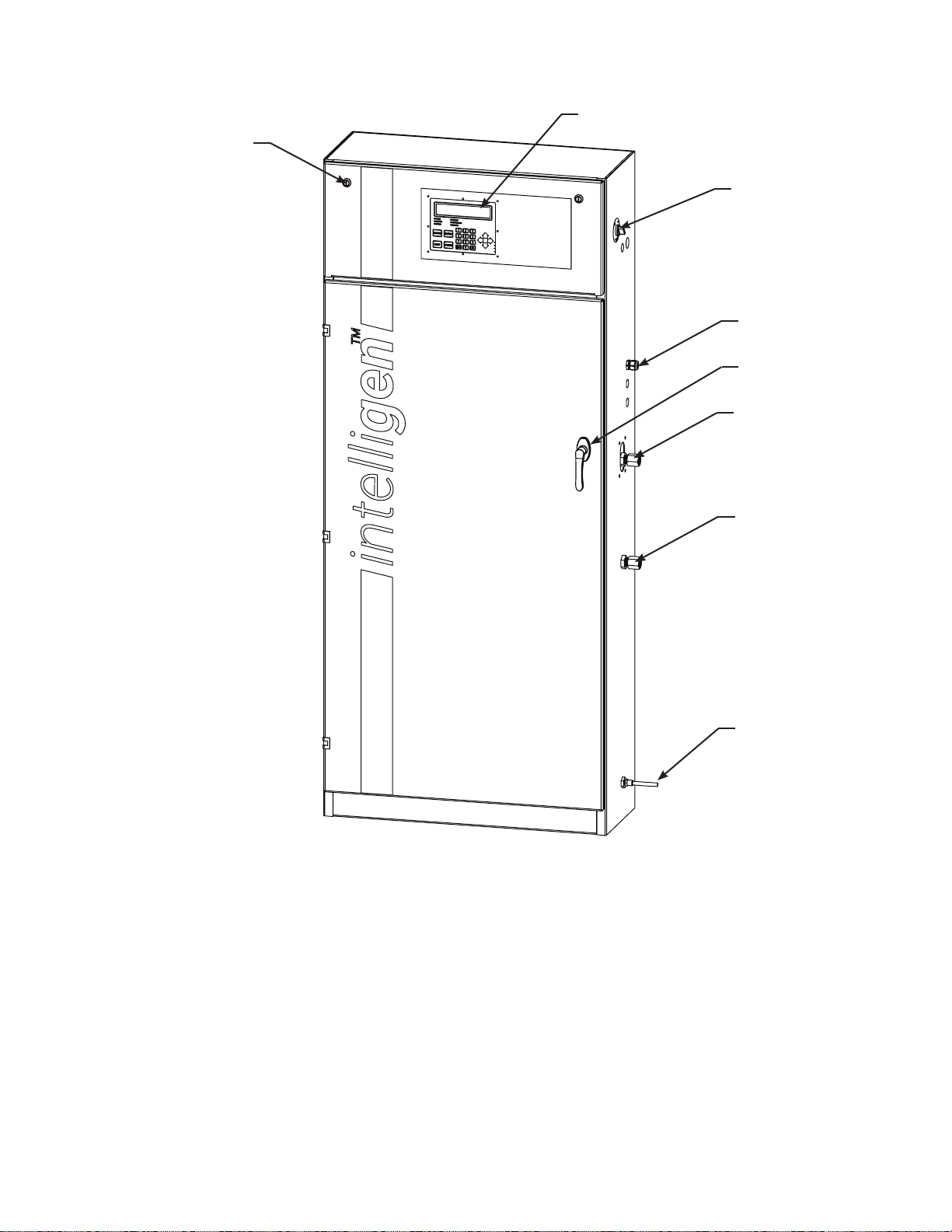
INS-1500/2000 (EU) Exterior View..................................................................................................................................................................7
INS-1500/2000 (EU) Interior View...................................................................................................................................................................8
INS-1500/2000 (EU) Nitrogen Tank View........................................................................................................................................................9
INS-1500/2000 (EU) Air Compressor View......................................................................................................................................................10
IntelliGen™Display ...........................................................................................................................................................................................11
Installation of the Nitrogen Generator...............................................................................................................................................................12
Wiring of the Nitrogen Generator......................................................................................................................................................................16
Air Compressor (380-415 VAC Three Phase) .........................................................................................................................................16
Compressor Sensor Wire..........................................................................................................................................................................17
Air Tank Blow-Down Located on the Bottom of the Tank Mounted Air Compressor (220 VAC).........................................................18
Nitrogen Cabinet (180-220 VAC)............................................................................................................................................................18
Internet Connectivity, PLINK, and BMS (Optional)...............................................................................................................................19
Nitrogen Generator Operation ...........................................................................................................................................................................20
Nitrogen Functionality Test ..............................................................................................................................................................................22
Filling the Sprinkler System and Purging..........................................................................................................................................................23
Purging with IntelliPurge®Nitrogen Purge Valve (INS-PV).............................................................................................................................24
Purging with Potter Nitrogen Purge Valve (NGP-SPV) ....................................................................................................................................25
IntelliView™Dashboard Internet Connectivity..................................................................................................................................................26
IntelliPurge®Wiring and Networking................................................................................................................................................................27
Maintenance and Part Replacements.................................................................................................................................................................28
Standard Maintenance........................................................................................................................................................................................29
Compressor Air Intake Filters..................................................................................................................................................................30
Air Tank Blow-down Strainer..................................................................................................................................................................31
Lubricated Air Compressor Oil................................................................................................................................................................31
Filter Elements.........................................................................................................................................................................................32
Resetting Maintenance Alert and Checking for Leaks ............................................................................................................................34
Air Compressor Replacement............................................................................................................................................................................35
Nitrogen Membrane Replacement.....................................................................................................................................................................35
Maintenance Alerts and Actions ........................................................................................................................................................................36
Trouble Alerts and Probable Causes..................................................................................................................................................................37
Troubleshooting.................................................................................................................................................................................................39
Leak on Sprinkler System or Nitrogen Generator ...................................................................................................................................39
Nitrogen Flow Rate and Nitrogen Purity Test .........................................................................................................................................39
Normal Operating Parameters of the INS-1500/2000 (EU) ..............................................................................................................................40
Nitrogen Generator Leak Detection System......................................................................................................................................................41
To Change the Leak Rate Warning Set Point.............................................................................................................................................42
To Change Sprinkler System Size..............................................................................................................................................................42
INS-1500/2000 (EU) Cabinet Dimensional Drawings......................................................................................................................................43
INS-1500/2000 (EU) Compressor Dimensional Drawings ...............................................................................................................................44
INS-1500/2000 (EU) Air Tank Dimensional Drawings.....................................................................................................................................45
INS-1500/2000 (EU) Piping Instrumentation Diagram.....................................................................................................................................46
Wiring Diagrams................................................................................................................................................................................................47
INS-1500/2000/2500 (EU) 380-415VAC Three Phase............................................................................................................................47
Menu Trees.........................................................................................................................................................................................................48
Menu Tree 1.............................................................................................................................................................................................48
Menu Tree 2.............................................................................................................................................................................................49
Menu Tree 3.............................................................................................................................................................................................50
Menu Tree 4.............................................................................................................................................................................................51
Menu Tree 5.............................................................................................................................................................................................52
Menu Tree 6.............................................................................................................................................................................................53
Menu Tree 7.............................................................................................................................................................................................54