INSTALLATION MANUAL: EVAX EVX-RM REMOTE MICROPHONE
5403671 Rev A 12/17
Evax by Potter • Phone: (888) 382-9835 • www.evax.com
PAGE 2 OF 4
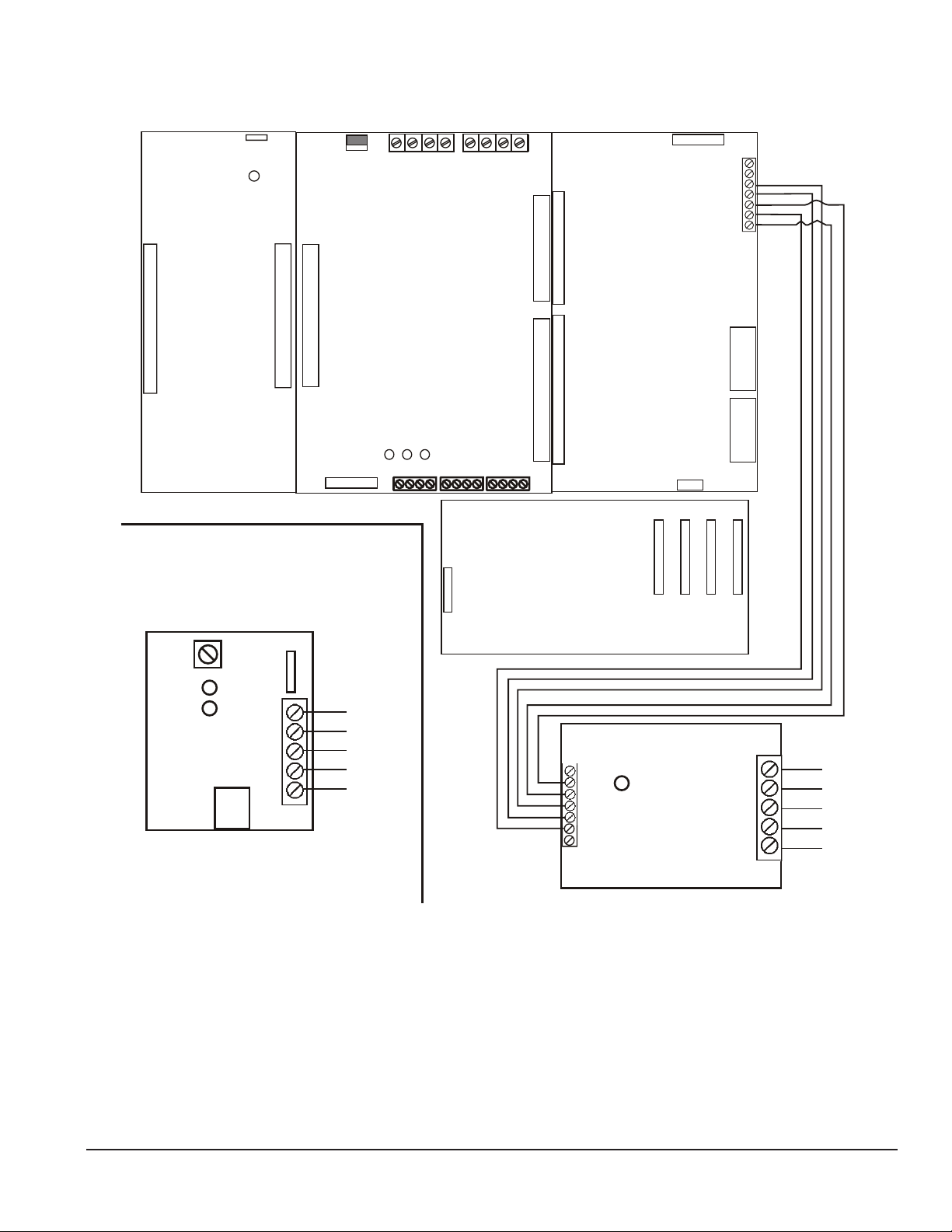
5. Terminal Designations
*EOLR is a 6/3 SIP 10K Resistor Network
to be installed on last EVX-RM only.
Wiring Detail Fig.1
**Maximum line resistance is dependent on
# of devices loading the line.
2 EVX-RM - 100W Max. Line Resistance
3 EVX-RM - 80W Max. Line Resistance
4 EVX-RM - 65W Max. Line Resistance
5 EVX-RM - 50W Max. Line Resistance
More than 5 EVX-RMs is not recommended
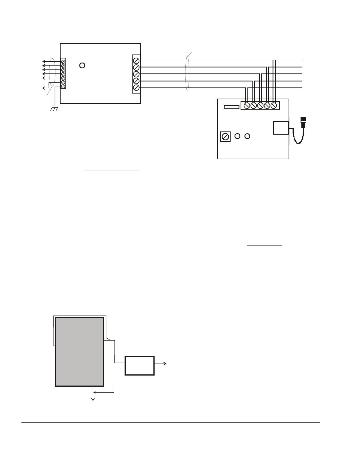
EVX-SC
V+
NEG
FAULT
PTT
AUDIO
3 pair Shielded
#22 AWG
TO
AX 25/50/100
Ter 11
Ter 10
Ter 6
Ter 2
Ter 1
Ter 8
T
B
2
T
B
3
*EOLR
MIC
GAIN
VR1
P1
ADDITIONAL
EVX-RM UNITS
*EOLR ON LAST UNIT ONLY
YEL RED
F
A
U
L
T
I
N
U
S
E
SUPERVISED
NON
SUPERVISED
All wiring is Power-Limited
Maximum Line Resistance
to last EVX-RM is 100Ω
per line.
Approx. 5000' of #22AWG
YEL
F
A
U
L
T
TB1
TB1
TB2
**
1
2
7
6
5
4
3
12345
1
2
3
4
5
EVX-SC must be mounted in same enclosure
as the EVAX 25/50/100 or in another UL
Listed cabinet within 20' in conduit.
* EVX-SC must be mounted using metal standoffs
or an Earth ground connection must be made
to TB2-7. Ground faults are indicated at 10K
impedance or less.
Terminal Designations
EVX-SC EVX-RM
TB2 TB1
Ter. 1 - MIC PTT +24 10mA Ter. 1 - V+ 24 VDC 0.04A
Ter. 2 - V+ 24 VDC 0.10A Ter. 2 - Ckt. Neg.
Ter. 3 - PTT +24V 10mA Ter. 3 - Fault +24V (Pull down 10mA)
Ter. 4 - Audio 1Vrms 10mA Ter. 4 - PTT +24V 10mA
Ter. 5 - Ckt Neg. Ter. 5 - Audio 1Vrms
Ter. 6 - Fault +24V 10mA
Ter. 7 - Earth Ground LED1
Fault (Yellow)
TB1
Ter. 1 - V+ 24 VDC LED2
Ter. 2 - Ckt Neg. In Use (Red)
Ter, 3 - Fault
Ter. 4 - PTT VR1
Ter. 5 - Audio 1Vrms Mic Gain (clockwise to increase)
LED1 P1
Fault (Yellow) 6 position modular jack
(connect to microphone)
EVAX 25/50/100
EVX-SC
T
B
3
T
B
2
TO
EVX-RM
TO
Battery cabling is Non-Power Limited
Do Not route any Power Limited wirin
within a ¼" of Battery cabling.
All wiring from EVX-SC is Power Limited.
All wiring must be routed to maintain minimum
spacing from any Non-power Limited wiring.
Specications
EVX-SC
Input Voltage - 24 VDC
Input Current - 0.030A DC Standby
- 0.050A DC Active
EVX-RM
Input Voltage - 24 VDC
Input Current - 0.020A DC Standby
- 0.040A DC Active
NOTE: When circuits are Power Limited,
use Power Limited cable as detailed in the
National Electrical Code, Article 760, such
as FPL or FPLP type cabling.
Field wiring connections:
#6-32 wire clamp screw 14-18 AWG
#8-32 wire clamp screw 12-18 AWG
Horizontal wire entry terminal 18-26 AWG
Wire gauge determined by circuit load