Introduction................................................................. 3
1. Installation Requirements.......................................... 5
General Information.............................................. 5
1.1 Gas Supply........................................................... 5
1.2 Electrical Supply................................................... 5
1.3 Location of Boiler.................................................. 7
1.4 Air Supply............................................................. 7
1.5 Flue Systems & Termibal Location....................... 7
1.6 Installation to an Existing System......................... 9
1.7 Hard Water Areas................................................. 9
1.8 System Requirements.......................................... 9
2. Boiler Installation.......................................................13
2.1 Unpacking ...........................................................13
2.2 Gas Connection...................................................13
2.3 D.H.W Supply......................................................13
2.4 C.H. Supply.........................................................14
2.5 Pressure Relief Valve..........................................14
2.6 Wiring the Appliance ...........................................15
3. Commissioning..........................................................16
3.1 Electrical Installation............................................16
3.2 Gas Installation....................................................16
3.3 Initial Lighting ......................................................17
3.4 Gas Pressure Adjustment ...................................18
3.5 Products of Combustion Measurement...............18
3.6 D.H.W Flow Rate ................................................19
3.7 Central Heating ...................................................19
3.8 Appliance Protection Devices..............................19
3.9 Complete the Installation.....................................20
4. Servicing & Routine Maintenance............................21
4.1 Remove the White Front Case............................22
4.2 Remove Base Panel............................................22
4.3 Remove the Air Box Covers................................22
4.4 Remove the Fan Assembly.................................22
4.5 Remove the Flue Hood .......................................22
4.6 Remove the Combust. Cham. Front Panel .........22
4.7 To Inspect and Clean the Boiler..........................22
4.8 To Remove the Burner........................................24
4.9 Gas Pressure Adjustment ...................................24
4.10 The Central Heating Sealed System...................24
4.11 Other Components..............................................24
5. Replacement of Parts...............................................26
5.1 Central Heating Overheat Thermostat...............27
5.2 Dom. H/Water Limit & Frost Thermostat............27
5.3 Sensor and Ignition Electrode............................27
5.4 Sensor and Ignition Leads .................................27
5.5 Burner ................................................................27
5.6 Injectors..............................................................27
5.7 Gas Valve...........................................................28
5.8 Modulating Valve................................................28
5.9 First Solenoid Valve...........................................28
5.1 Second Solenoid Valve......................................28
5.11 Case Seals.........................................................28
5.12 Central Heating and Boiler Switch .....................30
5.13 Electronic Control Boards ..................................30
5.14 Air Pressure Switch............................................31
5.15 Fan.....................................................................31
5.16 Fan Seals...........................................................31
5.17 Temperature Sensor D.H.W and C.H................31
5.18 Pressure Gauge.................................................31
5.19 Water Flow Switch D.H.W..................................32
5.20 Microswitch (D.H.W Flow Switch)......................32
5.21 Pump..................................................................32
5.22 Diverter Valve.....................................................33
5.23 Expansion Vessel C.H.......................................34
5.24 Expansion Vessel D.H.W...................................35
5.25 Heat Exchanger .................................................35
5.26 Automatic Air Vent .............................................36
5.27 Pressure Relief Valve.........................................36
5.28 Transformer Assembly.......................................37
5.29 Sight Glass with Securing Frame.......................37
6. Fault Finding.............................................................38
7. Electrical Layouts.....................................................39
Control Flow Sequence..............................................40
Functional Flow ..........................................................40
Electrical Diagram ......................................................41
8. Product Specification...............................................42
9. Optional Extras.........................................................43
10. Short List of Spares .................................................46
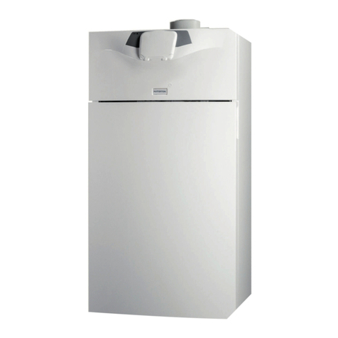
The model covered by these instructions is:-
Combi 80 G.C. No. 47-393-03

