Potterton Hallmark Installation and maintenance instructions

Supplied By www.heating spares.co Tel. 0161 620 6677
G.C. NO. 32 230 32
Installation & Service Instructions
Hallmark
Radiant Convector Gas Fire
THE GAS SAFETY (INSTALLATION AND USE) REGULATIONS 1994.
“In your own interest, and that of safety, it is law that all gas appliances are installed by competent persons, in accordance
with the above regulations. Failure to install appliances correctly could lead to prosecution.”
Installation must be in accordance with these Installation and Service Instructions and the rules in force.
The polythene bags used for packaging are a potential hazard to babies and young children and
MUST BE DISPOSED OF IMMEDIATELY.
LEAVE THESE INSTRUCTIONS WITH THE USER FOR USE ON FUTURE CALLS
For Use With Natural Gas
(G20) Only At 20mbar
For Use in GB
IMPORTANT
PLEASE READ THIS BOOK
BEFORE INSTALLING
OPERATING OR SERVICING
THIS APPLIANCE

Supplied By www.heating spares.co Tel. 0161 620 6677
2Contents Part No. 900/9350/1
Contents - Page 2
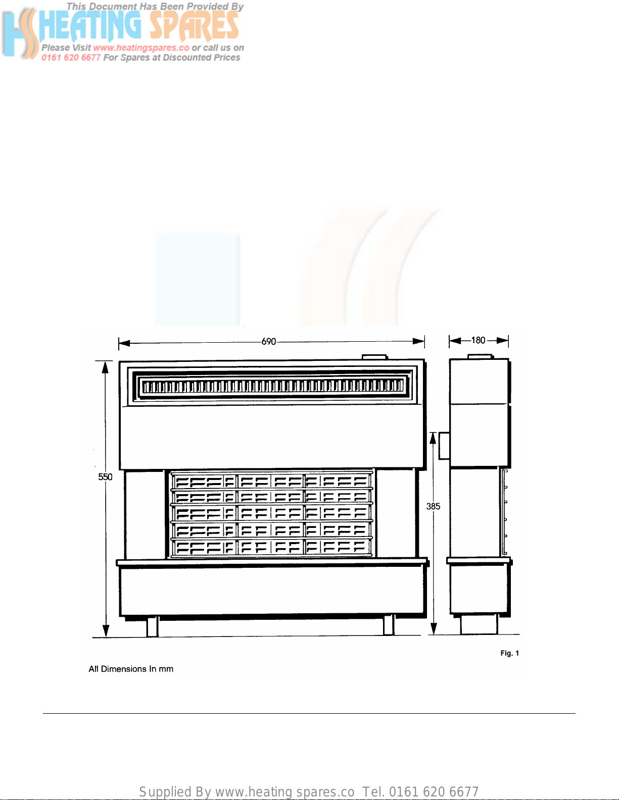
1. TECHNICAL DATA.................................................................................................................................................. 3
2. GENERAL................................................................................................................................................................ 4
3. INSTALLATION REQUIREMENTS......................................................................................................................... 4
3.1 Fire location....................................................................................................................................................... 4
3.2 Check The Chimney.......................................................................................................................................... 4
3.3 Combustible Wall Cladding................................................................................................................................5
3.4 Fireplace Opening .............................................................................................................................................5
3.5 Fire Surround & Shelves....................................................................................................................................5
3.6 Spigot & Spigot Extension................................................................................................................................. 6
3.7 Pre-Cast Flue.....................................................................................................................................................6
4. INSTALLATION....................................................................................................................................................... 6
4.1 Unpack the Fire .................................................................................................................................................6
4.2 Pre-Cast Flue.....................................................................................................................................................6
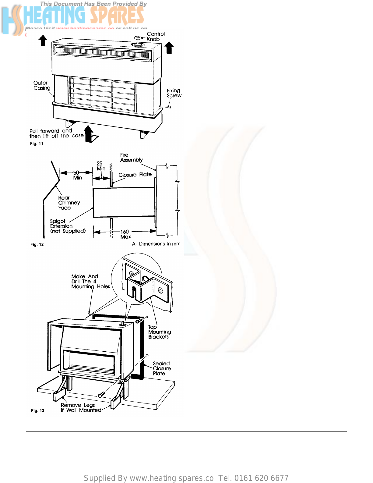
4.3 Closure Plate - Wall Mounted............................................................................................................................ 7
4.4 Closure Plate - Hearth Mounted........................................................................................................................ 7
4.5 Spigot Restrictor................................................................................................................................................ 7
4.6 Dis-assemble The Fire.......................................................................................................................................8
4.7 Mounting The Fire..............................................................................................................................................8
4.8 Prepare The Fire Connection ............................................................................................................................8
4.8.1 Gas Connection........................................................................................................................................ 9
5. CHECK GAS PRESSURE & OPERATION OF FIRE.............................................................................................. 9
6. TEST for SPILLAGE ............................................................................................................................................. 10
7. COMPLETE THE INSTALLATION........................................................................................................................ 11
8. CUSTOMER INFORMATION................................................................................................................................. 11
9. SERVICING & REPLACEMENT OF PARTS ........................................................................................................ 12
9.1 General Access ...............................................................................................................................................12
9.2 Burner and Electrode.......................................................................................................................................13
9.2.1 Electrode
9.2.2 Burner..................................................................................................................................................... 13
9.3 Gas Tap, Piezo And Injectors.......................................................................................................................... 14
9.3.1 Piezo....................................................................................................................................................... 14
9.3.2 Injectors.................................................................................................................................................. 14
10 SHORTLISTOFSPARES....................................................................................................................................... 15

Supplied By www.heating spares.co Tel. 0161 620 6677
Part No. 900/9350/1 Technical Data 3
1. Technical Data - Page 3
Input (Full On) 5.42 kW 19.51 MJ/h (18,500 Btu/h) Gross
Output (Full On) 3.25 kW 11.70 MJ/h (11,100 Btu/h)
(under typical flue pull conditions)
Input (Min.Setting) 1.67 kW 6.01 MJ/h (5,700) Btu/h) Gross
Injectors Bray Cat 28 size 195 (upper and lower)
Burner Bray No. AB 9516W, Duplex box type.
Cold Setting Pressure 18.9 mbar (7.4 in w.g.)
Hot Setting Pressure 18.9 mbar (7.4 in w.g.)
Ignition Rotary action impact piezo spark, integral with gas control tap
Gas Rate - Meter: 10 minutes after lighting, 2ft.3in approximately 6½ minutes
Weight (Nett) 16.9kg (37 Ibs) approx.
Gas Rate Adjustment: None
Aeration Adjustment: None
Electrical Connection: None
Gas Connection: Rc¼ (¼ in B.S.P.int) elbow in centre at back of fire
Data Plate: Fastened to inner casing on right hand side panel.
(Remove outer case for access).

Supplied By www.heating spares.co Tel. 0161 620 6677
4General & Installation Requirements Part No. 900/9350/1
2. General - Page 3
The Hallmark is an Radiant Convector gas fire, it is lit by a piezo spark igniter so batteries or electricity are not required.
The radiant heat is created by the use of ceramic radiants mounted centrally below the convector box.
IMPORTANT: Certain types of wallcoverings e.g. Blown Vinyl, are easily affected by heat. They may shrink and
discolour when close to a heating appliance. Please bear this in mind when installing the fire. Also,
because of the way hot air circulates naturally convected heat from the fire, dust or tobacco smoke
particles in the air will draw towards the wallcovering around the fire and may discolour it.
IMPORTANT: This fire MUST NOT be installed without its Closure Plate.
If you have any problems or questions concerning this appliance, please contact the Potterton Myson Technical
Help Line - Telephone (01926) 410044.
3. Installation Requirements - Page 3
3.1. Fire Location
The fire may be floor or wall mounted. The depth of the fireplace opening being a minimum of 165mm and the height to the
base of the spigot being a minimum of 250mm. A clearance of 50mm minimum between the end of the spigot and the
chimney. See Fig. 2.
A space of 765mm wide x 700mm high is required for installation. The height can be reduced where non combustible
materials are used. See Fig. 4.
A floor mounted fire must be on a non combustible hearth measuring at least 762mm wide and 305 deep. The hearth
material should be at least 12mm thick, see Fig. 3. Its top surface should be preferably be 50mm above the floor level in
order to discourage the placing of a rug over it. The fire MUST NOT be fitted directly onto a combustible floor. The fire is
suitable for installing in a normal brick chimney or a properly constructed Pre-Cast Flue.
3.2. Check The Chimney
a) The chimney must be swept immediately prior to
installation.
b) Remove any damper or register plate.
c) Any air supply e.g. underdraught openings etc., that
enter the fireplace other than via the closure plate
MUST BE COMPLETELY SEALED OFF.
d) Check that the chimney serves only one fireplace and
the base of the flue is clear of debris, bricking up etc.
e) Check also that the fireplace opening and the flue are
properly sealed so that combustion products do not
come in contact with combustible material outside the
flue passage.
f) Check for flue pull by applying a lighted taper, match or
smoke match into the fireplace opening. If there is a
definite flow into the opening proceed with the
installation. If not, pre-heat the flue for about 2 minutes
and re-check. If there is still no definite flow the flue may
require attention, so:
DO NOTPROCEEDANYFURTHER WITH THE
INSTALLATION UNTIL EXPERT ADVICE HAS BEEN
SOUGHT.

Supplied By www.heating spares.co Tel. 0161 620 6677
Part No. 900/9350/1 Installation Requirements 5
3. Installation Requirements - Page 5
3.3. Combustible Wall
If the wall against which the fire is to be installed has
combustible cladding or surround, the following conditions
must be met:
Note: Certain types of wall coverings may be prone to
discolouration.
a) The cladding must fit snugly to the wall face, any air
cavities must be sealed to prevent air leakage into the
chimney, which would spoil the flue pull.
b) Any combustible cladding (i.e. Wallpaper, etc) must not
extend more than 13mm behind the outer case of the
fire.
c) The cladding material must not extend inside the area
of the fireplace opening. Under no circumstances can it
be present inside the fireplace openings or flue
passage, or in any position which will allow direct
contact with the hot flue products.
d) The fire must discharge all its products inside the
fireplace opening in the wall. Use a flue spigot
extension (not Supplied) if necessary.
e) The engagement points for the fixing screws must be
adequate to support the fire solidly in all circumstances
through its life.
f) The minimum flat area is required to ensure that a
satisfactory seal can be made between the fireplace
and the appliance.
3.4. Fireplace Opening
For the dimensions of both wall mounted and
floor mounted fires, see Fig. 3.
3.5. Fire Surrounds & Shelves
a) This fire can be fitted to a non-combustible fire surround
and hearth or a propriety fire surround and hearth with a
1000C rating.
b) The surround must comply with the same minimum flat
area requirements as the fireplace opening. See Fig. 3.
The surround and hearth must be sealed to the floor &
wall to prevent air entrainment.
c) The hearth MUST be to the dimensions shown in Fig. 3.
and located centrally about the fireplace opening.
d) No permanent restriction should be placed within 75mm
of either side or top of the fire this will enable the outer
case to be removed for installation & servicing.
A combustible shelf can be fitted a minimum of 150mm
above the top point of the fire
provided that it does not stand out from the wall more than
150mm.
A shelf of non-combustible material up to 150mm deep may
be fitted above with a
minimum space of 75mm between the top
of the fire. See Fig 4.

Supplied By www.heating spares.co Tel. 0161 620 6677
6Installation Requirements/Installation Part No. 900/9350/1
3. Installation Requirements - Page 6
3.6. Spigot & Spigot Extension
The flue spigot or spigot extension MUST pass through the
closure plate by at least 25mm and have a minimum
clearance of 50mm between its opening & the nearest
obstruction.
3.7. Pre-Cast Flue
The fire is suitable for fitting into a properly constructed non
impeded pre-cast flues at least 3m high.
4. Installation
4.1. Unpack The Fire
The pack contains:
1Fire Assembly (with radiants)
2Flue Spigot
3Spigot Restrictor
4Closure plate
5Cooler Plate
6Poly Bag Assembly
7Reply Card
If any parts are damaged or missing please contact the
phone number shown on the check lists supplied with the
packs.
Do Not discard the packaging until all items are
accounted for or the fire is installed.
4.2. Pre-Cast Flue
Note: It must be emphasised that no mortar fangs between
the blocks should be extruded into the flue way. If raking
blocks are used they must be fitted according to the
manufacturers instructions. Mortar MUST NOT be allowed
to drop down and accumulate in the raked positions.
The spigot restrictor should NOT be fitted.
The cooler plate supplied must be formed at the markings
on the plate shown in Fig. 7.
Then fix to the rear face of the closure plate using the
screws provided. See Fig. 7.

Supplied By www.heating spares.co Tel. 0161 620 6677
Part No. 900/9350/1 Installation/Check Gas Pressure & Operation of Fire 7
4. Installation - Page 7
4.3. Closure Plate – Wall Mounted
Note: See Combustible Wall Cladding-page 5. This fire is
not suitable for use on combustible walls.
a) When wall mounted, the bottom of the fire must be at
least 150mm from the floor or top surface of any
combustible material, e.g. Rugs, Carpets, etc. See Fig 8.
before the fire is screwed to the wall.
b) The closure plate may be cut down in height so that the
sealing tape is not visible above the fire provided there is
still 13mm overlap of the plate along the top of the
fireplace opening.
c) If the closure plate has been reduced in size by trimming
off at the bottom, a new air relief opening MUST be cut.
See Fig. 10.
d) Tape the closure plate so the bottom edge is a minimum
of 93mm from the carpet. The bottom of the flue spigot
aperture will be 440mm above the carpet. See Fig 10.
4.4. Closure Plate - Hearth Mounted
Note: See Combustible Wall Cladding-page 5. This fire is
not suitable for use on combustible walls.
a) Fit the closure plate to the fire opening and seal around
the edges on all four sides.
b) Check the spigot and air relief openings in the plate are
not obstructed by any brickwork etc.
c) The closure plate may be cut down in height so that the
sealing tape is not visible above the fire provided there is
still 13mm overlap of the plate along the top of the
fireplace opening
4.5. Spigot Restrictor
Standard brick chimneys 228mm x 228mm. If over 4.3m in
height with a good flue suction the spigot restrictor should
be fitted.
It should not be used if:
a) The chimney is less than 4.3m.
b) The flue suction is poor.
c) The pre-cast flue is used irrespective of its height.
For example of the spigot restrictor see Fig. 7.

Supplied By www.heating spares.co Tel. 0161 620 6677
8Installation Part No. 900/9350/1
4. Installation - Page 8
4.6. Dis-assemble The Fire
a) Remove the dressguard
b) Carefully remove the radiant pack from the front of the
fire.
c) Pull off the control knob.
d) Remove the outer case by removing the two case
securing screws accessible through the lower holes in
the side panels. See Fig. 11.
e) Draw the case forward at the bottom and lift off.
f) Screw the flue spigot and spigot restrictor, (if required) to
the back panel using thescrews above and below the
flue aperture.
Note: The flue spigot may be extended to a maximum
total length of 160mm, measured from the back of
the fire if needed, for any of the following reasons:
1. If the fire is fitted to a recessed fireplace and the existing
flue spigot does not enter the closure plate by at least
25mm.
2. If an extension of the flue spigot backwards into a deep
fireplace would help clearance of products.
Note: In all cases the spigot or its extension should pass at
least 25mm through the closure plate. See Fig 12.
g) If the fire is to be wall mounted the two leg
assemblies should be removed.
4.7. Mounting The Fire
a) Offer the fire chassis to the closure plate and enter the
flue spigot into its aperture in the close plate.
b) Make sure the fire is level and mark the four mounting
holes, then remove the chassis and place to one side.
c) Drill and plug the wall (using No. 8 wall plugs).
d) Partially screw in the two top screws (using 38mm x
No.10 screws). Make sure they are firm enough in the
wall to support the fire.
d) Hang the fire on the two top screws and swing the flue
spigot through the closure plate aperture.
e) Fit the bottom screws and tighten all four screws up
securing the fire chassis to the wall.
4.8. Prepare The Fire Connection
The appliance shall be connected with rigid or semi-rigid
tubing.
The gas inlet is at the bottom rear centre of the appliance
under the convector box. An RC1A (¼inch BSP Internal
Taper) union elbow is provided and a suitable supply can be
directed through 3600 to the position required.

Supplied By www.heating spares.co Tel. 0161 620 6677
Part No. 900/9350/1 Installation/Check Gas Pressure & Operation of Fire 9
4. Installation - Page 9
4.8. Prepare The Fire Connection Cont.
IMPORTANT:
In all Installations, a means of isolating the main gas
supply must be fitted close to the fire, so the fire can
easily be removed for servicing.
When the fire is in position, the air relief opening is covered
by a deflector plate fastened to the back of the fire. See Fig.
14.
The deflector plate also covers the elbow union and must be
pivoted open before installation can take place, so proceed
as follows:
a) Remove the screw on the right of the deflector plate.
b) Open it by swinging it to the left.
4.8.1. Gas Connection
The fire can now be connected to the gas supply using left or
right hand side entry or rear entry as required.
If a concealed connection is required from the rear of the fire,
it will be necessary to cut a small clearance slot in the
closure plate.
5. Check Gas Pressure & Operation Of Fire
The test point screw is located on the Right hand side of the
fire under the gas tap.
a) Remove the pressure test point screw and connect a
pressure gauge. See Fig 15.
b) Carefully unpack the radiants. Insert the radiants under
the canopy, lift the bottom edge over the flange of the
radiant support plate and slide the radiant down behind
the rib of the radiant support. See Fig. 16.
Note: It is essential that the radiant falls forward
against the inside edge of the canopy.
c) Fit the control knob.
d) Turn ON the gas supply and test all joints for gas
soundness. Then purge the installation in accordance
with B56891.
e) Push in the control knob and turn slowly anticlockwise,
until a loud click is heard. The burner should be lit.
It may be necessary to repeat this operation several times
before all the air is purged from the line. Push in and turn the
knob clockwise back to ‘0’ between each attempt.

Supplied By www.heating spares.co Tel. 0161 620 6677
10 Gas Connection/Test for Spillage Part No. 900/9350/1
5. Check Gas Pressure & Operation Of Fire - Page 10
5.0. Check Gas Pressure & Operation Of Fire
- Cont.
f) Once the burner is lit, the fire should remain on the its
maximum setting 6 .
g) Check the gas pressure, it should be:-
18.9mbar ± 0.5mbar (7.4in w.g. ± 0.2in w.g.).
This pressure will only be obtained if the
incoming gas pressure is 20mbar (8in w.g.).
h) Push in and turn the control knob through to ‘OFF’.
i) Disconnect the pressure gauge, re-fit the pressure test
point screw and test for gas soundness.
j) Close the air relief deflector plate, re-fit the screws.
6. Test For Spillage a) Close all doors and windows, re-light the fire and turn to
setting ‘6.
b) After 1 0 minutes the fire will be ready to test for spillage.
Expose the test hole by slackening off the screw holding
the cover plate in position and pivot it to the left. See Fig.
17.
c) light a smoke match and position in the test hole as
shown in Fig. 17. The complete head of the smoke
match should be inserted into the hole.
d) If the flue is pulling normally, all the smoke will be drawn
into the chimney.
e) if there are is any downblow or if the smoke seems to
drift from the hole this shows spillage.
f) Turn off the fire, disconnect from the supply and remove
the spigot restrictor. Repeat the smoke test
g) If any sign of spillage persists the chimney is faulty. The
cause of the faulty chimney must be rectified, before
leaving the fire installed.
Note: Possible causes of poorflue performance are blocked
or partially blocked chimney (cured by sweeping) or
downblow (cured by fitting a suitable cowl).
IF THE FAULT CANNOT BE CORRECTED, TURN OFF
AND DISCONNECT THE FIRE. SEEK EXPERT ADVICE.
h) If the test is successful, turn the fire off and complete the
installation.

Supplied By www.heating spares.co Tel. 0161 620 6677
Part No. 900/9350/1 Customer Information 11
7. Complete The Installation
a) Remove the control knob.
Before re-fitting the outer case, show the customer the
data badge and advise them to write the serial number in
the space provided in the Instructions For Use - Page 6.
b) Make sure the large flat washer between the fire chassis
and the outer casing at the top of the control rod is in
position.
c) Fit the outer case at the top first by locating the two pegs
on the back panel into their holes in the case. Swing the
front of the case into position. See Fig. 18.
d) Replace the case securing screws (one each side).
e) Re-fit the control knob and dressguard.
8. Customer Information
Make sure the customer knows how to operate the fire and
clearly understands the following:
a) The control knob must be pressed down before the fire
can be turned ON or OFF.
b) The control knob should be turned slowly anticlockwise
and the spark igniter will operate during the turning of the
tap.
c) The fire can be lit by a taper if necessary. To do this,
light the taper and apply it to the base of one of the
centre radiants. Then turn the control knob anticlockwise
to setting ‘6’
d) The control knob has numbers to help find the best
setting, but it is not a thermostat. See Fig. 19.
e) The Radiants can be replaced if necessary. Demonstrate
the removal of the dressguard and the replacement of
the Radiants. See Fig.16.
f) Explain to the user that the fire should be service
regularly, or as recommended by the local Gas Authority,
for continued safe and efficient operate.
g) That certain types of wall coverings, e.g. Blown Vinyl, are
easily affected by heat. They may shrink and discolour
when close to a heating appliance. They should bear this
in mind when decorating the room. Also, because of the
way hot air circulates naturally convected heat from the
fire, dust or tobacco smoke particles in the air will be
drawn towards the wallcovering around the fire and may
discolour it.
Leave these Installation and Service Instructions with the User for use on future calls.

Supplied By www.heating spares.co Tel. 0161 620 6677
12 Part No. 900/9350/1
9. Servicing & Replacement of Parts
# When servicing the fire, always remove dust and debris from the burner and fire interior.
# We recommend that the complete fire is removed from the fireplace opening and the following steps performed:-
Clear the opening of dust and debris.
Check the chimney to ensure continued clearance of combustion products and that there is no excessive build
up of soot.
9.1. General Access
a) Ensure the gas supply to the fire is OFF.
b) Carefully pull off the control knob.
c) Remove the two screws fixing screws from each side of
the case.
d) Carefully draw the case forward at the bottom and lift
off.
On re-assembly, check the large flat washer at the top of
the control rod is in position. Make sure the case is located
correctly on the two location pegs on the top of the heat
exchanger, before securing the case with two screws.

Supplied By www.heating spares.co Tel. 0161 620 6677
Part No. 900/9350/1 Servicing & Replacement of Parts 13
9. Servicing & Replacement of Parts - Page 13
9.2. Burner and Electrode
a) Perform General Access - 9.1.
b) Disconnect the Gas supply union from the tap.
c) Remove the screw securing the burner to the right hand
end of the burner plate.
d) Slacken the screw and wingnut securing the burner to
the left hand end of the burner plate.
e) Slide the burner to the right and lower to the floor.
The burner and electrode are accessible for servicing.
9.2.1 Electrode
a) Remove the electrode lead.
b) Remove the nut and washer securing the electrode to
the burner. The spark gap at the electrode should be 3-
4mm. See Fig. 22.
9.2.2. Burner
a) Remove the locknut securing the tap to the burner.
b) Remove the electrode as above and clean or replace the
burner.
On re-assembly make sure the large flat washer is fitted to
the top of the control rod between the fire chassis and the
outer case.
Check for gas soundness and for the correct operation of the
fire.

Supplied By www.heating spares.co Tel. 0161 620 6677
14 Part No. 900/9350/1
9. Servicing & Replacement of Parts - Page 14
9.3. Gas Tap, Piezo And Injector
a) Perform General Access -9.1.
b) Remove the split pin connecting piezo to the control rod.
c) Disconnect the union nut securing the gas pipe to the
tap.
d) Disconnect the electrode lead from the piezo unit.
e) Remove the lock nut securing the tap to the burner.
Now either the Injectors or the piezo can be removed.
9.3.1 Piezo
a) Remove the two screws securing the piezo to tap. Be
careful to retain the small spring housed between the tap
and the piezo.
Note: When re-fitting the piezo to the tap, make sure the
small spring is housed in the piezo. The engaging
ribs at the base of the piezo should also be seated
correctly in the tap slots, before securing with the
two screws.
9.3.2 Injectors
Remove the two injectors.
The injectors are of the double ceramic tipped design and the
holes should be cleaned by immersion in a suitable solvent.
DO NOT CLEAN OUT with a pin or any other similar
implement. A broken orcracked injector must be replaced
with a new one.
Notes on re-assembly - Use a suitable sealing
compound on the threads.
e) Check for gas soundness and correct operation of the
fire.

Supplied By www.heating spares.co Tel. 0161 620 6677
Part No. 900/9350/1 Short list of Spares 15
10. Short List Of Spares
Key
No G.C.
No Description No
Off Makers
Part No
23 382 594 Electrode - APCO 7854 1900/9446
26 145 845 Electrode Lead 1900/9393
27 386 861 Control Tap Assembly (Concentric JC/A/91 5).
Includes Key No. 30 1904/1044
29 398 493 Injector - Bray Cat.28 Size 195 2900/705
30 397 730 Piezo Generator - Concentric No. JC/SA/2130 1904/9387
61 127 038
127 046 Control Knob Assembly Handicapped Person Control
Knob Assembly 1
1900/1051
900HP/1 051
63 145 898 Radiant 4900/9347
64 145965 Dressguard 150/900/759
Back Page
Table of contents