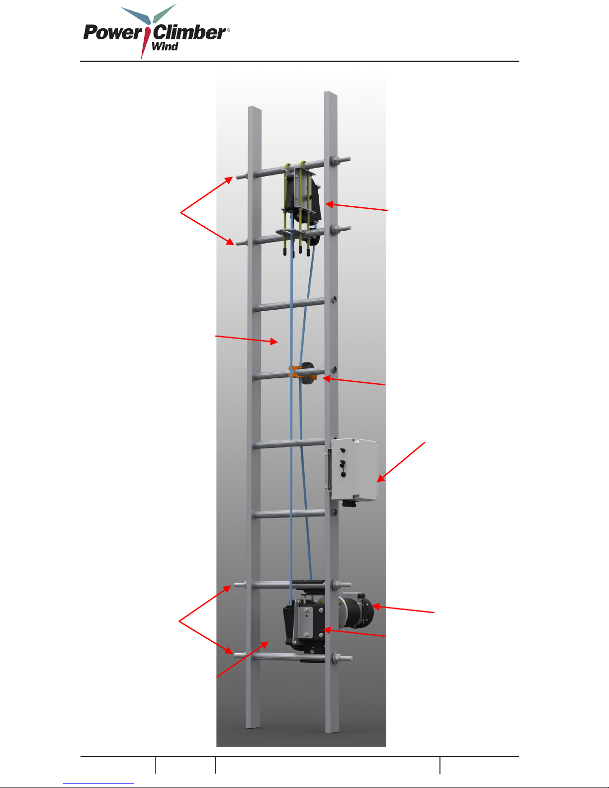
3.3. Upper Assembly NOTE: Tools Required: 17mm
combination wrench and Two (2)
29mm Wrenches, Lift Bag capable of
holding all tools and components.
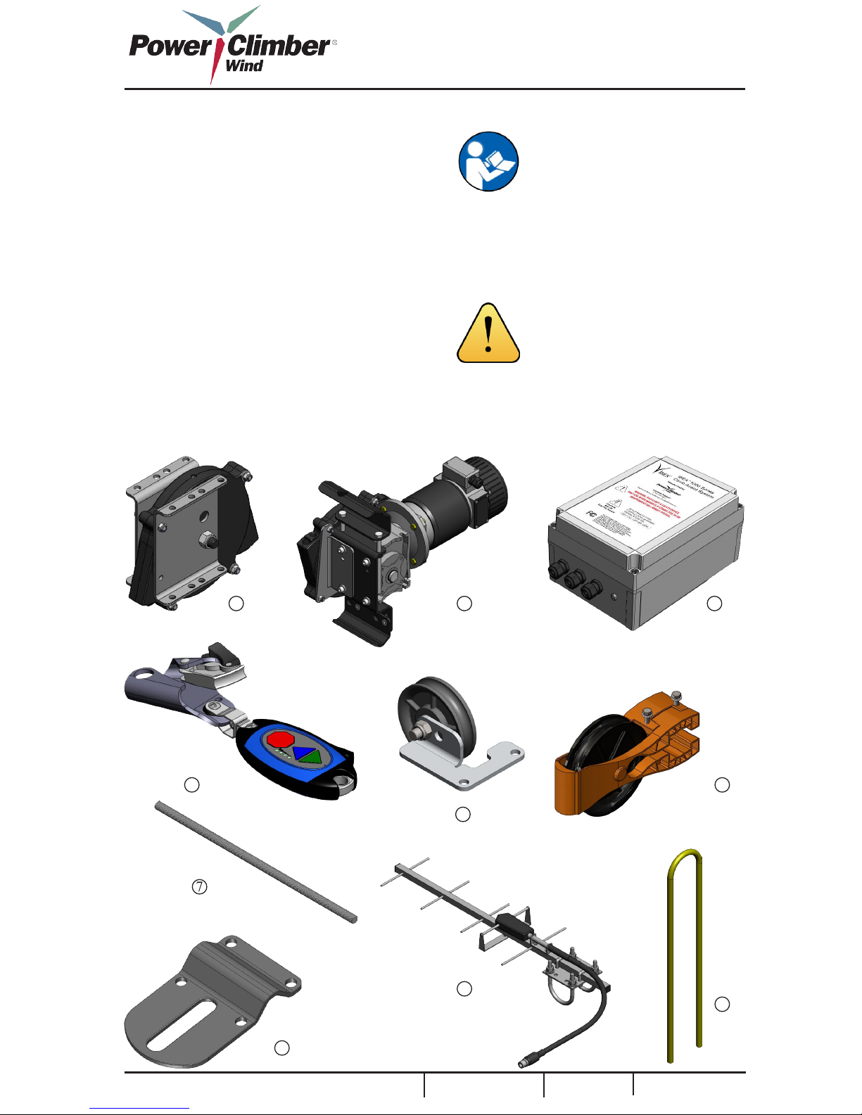
1. Unpack the following and place in the Lift Bag:
Item Description Qty
1 Upper Sheave Assembly 1
2 10mm U-Bolt 2
3 Stop Plate 1
4 Pull-In Roller MS
5 Rung Reinforcements 2
6 Roller 1
7 Upper Sheave Hardware Kit 1
(Not Shown)
1
2
3
4
5
2. Choose the mounting position. The Upper
sheave should be mounted approximately in line
with the lower sheave. The upper sheave ideally is
installed 6-7 rungs above the nal tower platform.
If the installation height is limited, care must be
taken to insure safe disengagement from the sys-
tem is possible at the installed height.
3. Install Rung Supports in the rungs directly
above and below the Upper Sheave mounting
position. Thread four (4) ¾” or M20 for EU Nuts,
Lock-Washers, and Fender Washers and tighten
until Lock-Washers have been fully compressed
using 29mm Wrenches.
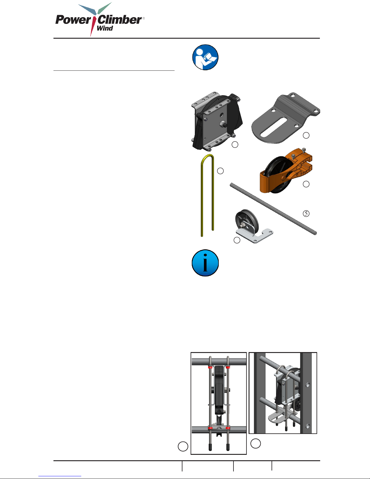
4. Install the Upper Sheave Assembly.
4A. Unpack the Upper Sheave, (2) U-Bolts, (1)
Rung Support Bracket and Upper Hardware
Kit Hold the Upper Sheave in place and install the
(2) 10mm U-Bolts over the top supported rung and
through the upper and lower mounting holes on the
climber side and thread on two (4) nuts with star
lock with star facing up move them up the U-Bolt.
Install (4) nuts with star lock with star facing
down. Adjust nuts up the U-Bolt to make room for
the Rung Support Bracket to t over the bottom
supported run
4B. Tighten (4) upper nuts with star lock until
the Upper Sheave Bracket is tight to the upper
supported rung. Tighten (4) lower nuts with star
lock until the Rung Support Bracket is tightly rest-
ing on the lower supported rung. Be sure the Rung
Support Bracket appears to be level in all direc-
tions and tighten evenly all (4) nuts with star lock
until Upper Sheave is rmly secured to the ladder.
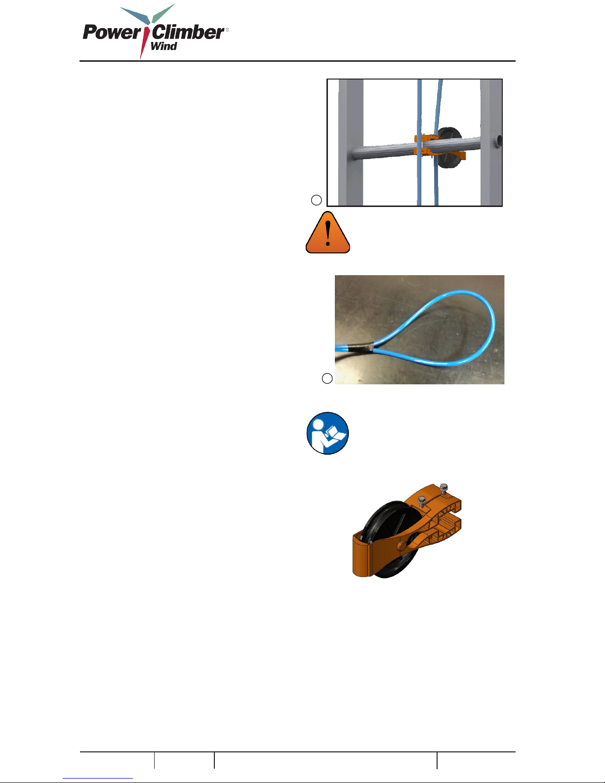
4C. Install 705519-1 roller using supplied nuts.
Align holes with the U-Bolt on non-climbing side
of ladder, slide up until it is ush with stop plate.
Tighten bolts until snug.
4D. Install (4) rubber boots to end of U-Bolts.
TIP: If two rungs or less exist above
deck level, installation may be pos-
sible just below deck level. This
will require user to disconnect from
the IBEX®while on the ladder, but
connection to fall arrest system must
be maintained.
4B 4C
6
Page 9 of 24
Reference: 702991-1 Issue date: 26-Jan-2012 Revision: E Reference: 702991-1 Issue date: 26-Jan-2012 Revision: E