Power Climber Wind BAP 360 User manual

Reference: 38741
Issue date: 2018-JUL-24
Revision: L
Page 1 of 37
BLADE ACCESS PLATFORM
TYPE: BAP 360°
OPERATION AND INSTALLATION INSTRUCTIONS
CONFORM TO THE
MACHINE DIRECTIVE 2006/42/EC
EN 1808 was used as guiding base for the design
WARNING:
All persons operating this equipment must read and completely understand this manual.
All persons must be thoroughly trained in the use of the equipment, it’s operational and
safety features, and they must also be capable of carrying out the daily checklist.
Only authorized and physically fit persons shall operate the equipment.
Any operation in violation of these instructions is at the operator’s own risk and may result
in serious injuries.
Keep this manual with the platform at all times.
Only use spare parts and steel wire rope from POWER CLIMBER WIND

Reference: 38741
Issue date: 2018-JUL-24
Revision: L
Page 2 of 37
1. General View ......................................................................................... 3
2. Specifications........................................................................................ 3
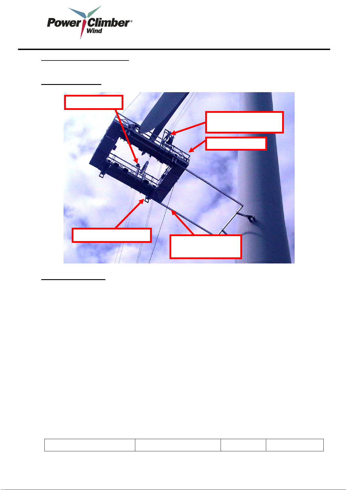
3. Rigging of the Steel Wires at the Nacelle............................................ 4
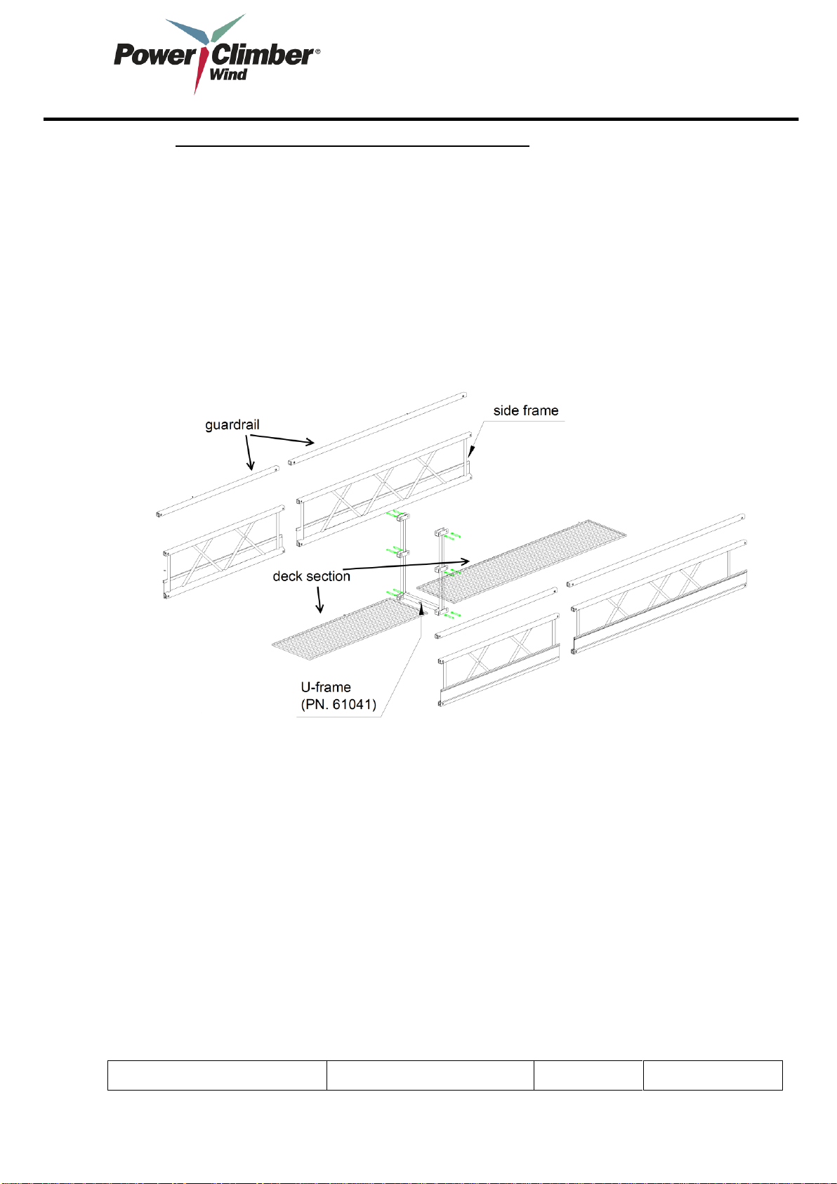
4. Assembly of the BAP 360°.................................................................... 5
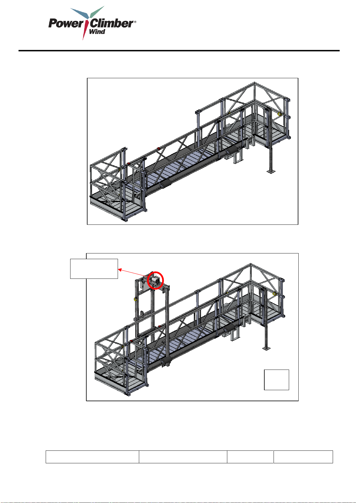
5. Overview of Assembled Platform ...................................................... 21
6. Operation of the Blade Access Platform........................................... 23
7. Instructions & Precautions Before Starting and During Operation. 25
8. Hoist Specifications and Features..................................................... 28
9. Reeving of Steel Wires ....................................................................... 29
10. Maintenance...................................................................................... 31
11. Trouble shooting............................................................................... 32
12. Safety Features ................................................................................. 33
13. Steel Wire Specs and Inspection Criteria........................................ 35
14. General Caution And Precautions ................................................... 36
15. Daily Test........................................................................................... 37
Manufacturer:
Power Climber Wind b.v.b.a,
Satenrozen 7,
B-2550
Kontich BELGIUM
Phone: +32-3-451 05 00
Fax ; +32-3-451 05 01
Email: info@PowerClimber.be

Reference: 38741
Issue date: 2018-JUL-24
Revision: L
Page 3 of 37
www.powerclimberwind.com
1. General View
2. Specifications
Verification needs to be done to make sure that the size of the BAP platform is suitable for the
given blade parameters. Form with blade dimensions and parameters to be completed.
General Specifications
The platform is designed to inspect and to perform any necessary maintenance or repairs to the
blades of wind turbines.
The platform is built with Power Climber Wind Modulo Platform elements. Two Titan hoists Type
653-CE are used to power the platform. Attached to the bottom of the rectangular platform is an
aluminium sub frame. The sub frame is actuated with a manual winch to push the platform away
from the tower to access the blade. Double pneumatic castor rollers are used to engage the
tower and roll along during ascent and descent.
Subframe/
stabilization frame
Walk-through Stirrup
x2
Roller Stanchions x4
Winch Assembly
Modulo Platform

Reference: 38741
Issue date: 2018-JUL-24
Revision: L
Page 4 of 37
General Specifications
Total self-weight
1075 kg
Max. Payload
225 kg
Lifting capacity Titan hoists 2 x 650 kg
1300 kg
Max number of Persons
2
Lifting speed
8,5 m/min
Max Distance from Tower to Blade Tip
10,4 m
Min. Distance from Tower to blade
840 mm
Distance between suspension wires
2960 mm
Overall internal Dimensions L x W
4390 mm x 2200 mm
Total Height
2850 mm
Power Supply
3x400V/50 Hz ( 3Ph+N+E)
Power rating Titan hoists
2 x 1.8 HP
Max wind speed not continuously guided
10 m/sec
Max wind speed continuously guided with tag line
12,5 m/sec
3. Rigging of the Steel Wires at the Nacelle
Rigging of the steel wires may only be done by trained installers.
Rigging points must have a minimum rating of 3 x WLL = 3 x 650 kg
When using slings, use 1 sling for the safety wire and 1 sling for the suspension
wire.
Minimum rated load of slings is 2000 kg ( Green Slings)
Only steel wires recommended by Power Climber Wind may be used.
The top limit striker plates can be fixed to the suspension wires under the hook
before lifting the wire to the nacelle. This to avoid the need to install the top plate
from the platform.
The distance from the striker plates to the nacelle has to be carefully determined
so to limit the angle of the steel wires to maximum 15°. This distance has to be
calculated with the specific turbine parameters.

Reference: 38741
Issue date: 2018-JUL-24
Revision: L
Page 5 of 37
4. Assembly of the BAP 360°
NOTE: Length to be measured between the bottom holes of the sideframe.
A. Bill of Material
Before assembling the BAP 360° make sure following components are present:
For the MODULO®platform:
A. 4 x Corner section with 2 U frames attached ( PN 61054+2 x PN 61041 )
B. 2 x Deck section 1274 mm ( PN 61025-1274 )
C. 4 x Side frame 1274 mm ( PN 61027-1274 )
D. 4 x Guard rail 1274 mm ( PN 61026-1274 )
E. 2 x Deck section 2375 mm ( PN 61025-2375 )
F. 4 x Side frame 2375 mm ( PN 61027-2375 )
G. 4 x Alu Guard rail 2375 mm ( PN 61026-2375 )
H. 2x Extra U frame ( PN 61041 )
I. 2 x Deck 980 mm ( PN 61025-0980 )
J. 4x Side Frame 980 mm ( PN 61027-0980 )
K. 4 x guard rail 980 mm ( PN 61026-0980 )
L. 120 x SafeFix pins ( PN 61049 )
M. 2 x Walk-through Stirrup ( Assembly )
N. 8 x Soft Wall Roller ( PN 61046)
O. 2 x Titan Hoist ( PN 9091 3 phase unit )
Table of contents