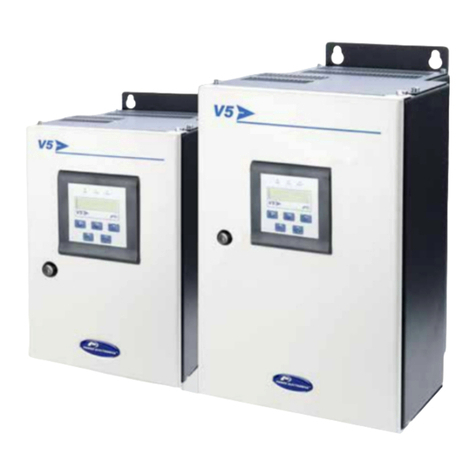
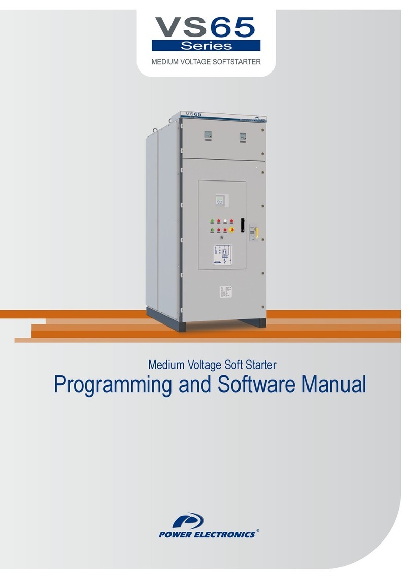
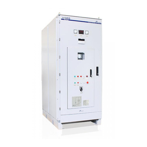
Power Electronics VS65 Series User manual

Getting Started Manual
MEDIUM VOLTAGE SOFTSTARTER


medium voltage soft starter
Getting Started Manual
Edition: November 2008
VS65IM01AI Rev. A

VS65 POWER ELECTRONICS
2

POWER ELECTRONICS VS65
3
SAFETY SYMBOLS
Always follow safety instructions to prevent accidents and potential hazards from occurring.
Edition of November 2008
This publication could present technical imprecision or misprints. The information here included will be
periodically modified and updated, and all those modifications will be incorporated in later editions.
To consult the most updated information of this product you might access through our website
www.power-electronics.com where the latest version of this manual can be downloaded.
WARNING This symbol means improper operation may results in serious personal
injury or death.
CAUTION Identifies shock hazards under certain conditions. Particular attention should
be given because dangerous voltage may be present. Maintenance
operation should be done by qualified personnel
Identifies potential hazards under certain conditions. Read the message and
follow the instructions carefully.
Identifies shock hazards under certain conditions. Particular attention should
be given because dangerous voltage may be present.

VS65 POWER ELECTRONICS
4
Revisions
Date Revision Description
30 / 11 / 2008 A First edition

POWER ELECTRONICS VS65
INDEX 5
INDEX
SAFETY INSTRUCTIONS........................................................................................................... 7
1. INTRODUCTION.................................................................................................................. 11
1.1. Overview .................................................................................................................... 11
1.2. Technical Indicators and Performance....................................................................... 11
1.3. Design Features......................................................................................................... 12
1.4. Operating Principle..................................................................................................... 13
1.5. Protection for Motor and System................................................................................ 14
2. INSTALLATION AND CONNECTION.................................................................................. 16
2.1. Acceptance and Unpacking ....................................................................................... 16
2.2. Initial Inspection ......................................................................................................... 16
2.3. Operating Environment .............................................................................................. 16
2.4. Power Connections.................................................................................................... 16
2.5. Control Terminals Description.................................................................................... 17
2.6. Connection and Usage of Control Terminals ............................................................. 18
3. STANDARD RATINGS ........................................................................................................ 20
3.1. Designation Code....................................................................................................... 20
3.2. Table of Standard Ratings ......................................................................................... 21
4. PROGRAMMING KEYBOARD............................................................................................ 22
4.1. Display and Keyboard ................................................................................................ 22
4.2. Function Code Table and Description........................................................................ 22
4.3. Function Codes Explanations .................................................................................... 23
4.4. How to Program ......................................................................................................... 28
5. POWERING ON AND RUNNING......................................................................................... 30
5.1. Low-Voltage Trial Run................................................................................................ 30
5.2. High-Voltage Trial Run............................................................................................... 31
5.3. Data Display in Running............................................................................................. 31
6. FAULT MESSAGES. DESCRIPTIONS AND ACTIONS...................................................... 32
6.1. Fault Code Table........................................................................................................ 32
6.2. Fault History............................................................................................................... 33
7. COMMUNICATION PROTOCOL ......................................................................................... 34
7.1. Profibus Protocol........................................................................................................ 34
7.2. Modbus Protocol ........................................................................................................ 38
8. ANNEXE A. POWER CABINET OPERATION..................................................................... 41
8.1. Switch Operation of Power Cabinet ........................................................................... 42
8.2. Control Panel of Power Cabinet................................................................................. 42
9. ANNEXE B. ELECTRICAL AND MECHANICAL DRAWINGS............................................ 54

POWER ELECTRONICS VS65
SAFETY INSTRUCTIONS 7
SAFETY INSTRUCTIONS
IMPORTANT!
Read this manual carefully to maximise the performance of this product and to ensure its safe
use.
In this manual, safety messages are classified as follows:
WARNING
Do not remove the cover while the power is applied or the unit is in operation.
Otherwise electric shock could occur.
Do not run the softstarter with the front cover removed.
Otherwise you may get an electric shock due to the high voltage terminals or exposure of
charged capacitors.
Do not remove the cover except for periodic inspections or wiring, even if the
input power is not applied.
Otherwise you may access the charged circuits and get an electric shock.
Operate the switches with dry hands.
Otherwise you may get an electric shock.
Do not use cables with damaged insulation.
Otherwise you may get an electric shock.
Do not subject the cables to abrasions, excessive stress, heavy loads or pinching.
Otherwise, you may get an electric shock.
CAUTION
Install the softstarter on a non-flammable surface. Do not place flammable material
nearby.
Otherwise fire could occur.
Disconnect the input power if the softstarter gets damaged.
Otherwise it could result in a secondary accident or fire.
Do not apply power to a damaged softstarter or to a softstarter with parts missing
even if the installation is complete.
Otherwise you may get an electric shock.
Do not allow lint, paper, wood chips, dust, metallic chips or other foreign matter
into the softstarter.
Otherwise fire or accident could occur.

VS65 POWER ELECTRONICS
8 SAFETY INSTRUCTIONS
WARNINGS
RECEPTION
The VS65 softstarters are carefully tested and perfectly packed before leaving
the factory.
In the even of transport damage, please ensure that you notify the transport
agency and POWER ELECTRONICS: 902 40 20 70 (International +34 96 136
65 57) or your nearest agent, within 24hrs from receipt of the goods.
UNPACKING
Make sure model and serial number of the variable speed drive are the same
on the box, delivery note and unit.
Each softstarter is supplied with a technical manual.
RECYCLING
Packing of the equipments should be recycled. For this, it is necessary to
separate different materials included (plastic, paper, cardboard, wood, ...) and
deposit them on proper banks.
Waste products of electric and electronic devices should be selectively
collected for their correct environmental management.
SAFETY
Before operating the softstarter, read this manual thoroughly to gain and
understanding of the unit. If any doubt exists then please contact POWER
ELECTRONICS, (902 40 20 70 / +34 96 136 65 57) or your nearest agent.
Wear safety glasses when operating the equipment with power applied and the
front cover is removed.
Handle the softstarter with care according to its weight.
Do not place heavy objects on the softstarter.
Ensure that the mounting orientation is correct.
Do not drop the softstarter or subject it to impact.
The VS65 softstarters contain static sensitive printed circuits boards. Use static
safety procedures when handling these boards.
Avoid installing the softstarter in conditions that differ from those described in
the Technical Characteristics section.

POWER ELECTRONICS VS65
SAFETY INSTRUCTIONS 9
PRECAUTIONS
Electric shock prevention:
The enclosure of the starter cabinet must be grounded properly to keep away
from the electric shock even if electric leakage on the enclosure. Disconnect all
power supplies before maintenance for soft starter or motor. Due to storage
function of internal RC circuit, the triggering component will keep dangerous
voltage even if the main power supply is cut off. Use a connection wire to
short-circuit it with ground in order to discharge the voltage.
Compensation capacitance:
The non-active power compensation capacitance is used to raise power factor
must be connected to VS65 soft starter’s input terminal and not connect to the
output terminal; otherwise, the soft starter’s controlled silicon power device
may be damaged.
Insulation test:
To test voltage withstanding ability of the 3-phase supply to ground, have to
take off all circuit control boards. Using a M ohm meter to measure the
insulation voltage withstanding of control board to ground is also forbidden.
Low-voltage test:
The test should be strictly in accordance with operating instructions. The low-
voltage terminal of the voltage transformer should be disconnected.
Input & output:
Do not make mistakes when connecting input and output terminals of the VS65
soft starter’s main loop; otherwise, there may be result in the unexpected
actions of the soft starter, which could damage the starter and motor.
TRIAL RUN
Before commissioning the softstarter, please, read section 8 of this manual
referred to power cabinet.
Verify all parameters before operating the softstarter. Alteration of parameters
may be required depending on application and load.
Always apply voltage and current signals to each terminal that are within levels
indicated within this manual. Otherwise, damage to the softstarter may result.
EARTH CONNECTION
Connect only to the dedicated ground terminal of the softstarter. Do not use the
case or the chassis screw for grounding.
When installing, grounding wire should be connected first and removed last.
The earth cable must have a minimal cross sectional area that meets local
country electrical regulations.
Motor ground must be connected to the softstarter ground terminal and not to
the installation’s ground. We recommend that the section of the ground
connection cable should be equal or higher than the active conductor.
Installation ground must be connected to the softstarter ground terminal.

VS65 POWER ELECTRONICS
10 SAFETY INSTRUCTIONS

POWER ELECTRONICS VS65
INTRODUCTION 11
1. INTRODUCTION
This chapter will introduce the VS65 Medium and High voltage solid starter series, describing their
appearance, functions and operations. We recommend that new users read this chapter and acquire an
overall understanding before operating the soft starter.
1.1. Overview
A complete VS65 includes: main circuit-breaker, control transformer, control module, silicon
controlled module, motor protecting module, and high-voltage vacuum bypass contactor. The soft
starting part includes: control module, control transformer, silicon controlled module, and high-voltage
vacuum bypass contactor.
1.2. Technical Indicators and Performance
Input voltage 2300VAC, 3300VAC, 4160VAC, 6600VAC, 10 ~15kVAC (-10% to +10%)
Insulation voltage 6900V, 9900V, 12500V, 19500V, 30000 ~45000V
Input frequency 50 ~60Hz ±2Hz (Automatic selection)
INPUT
Control voltage 220VAC, 50Hz
Motor output voltage 2300VAC, 3300VAC, 4160VAC, 6600VAC, 10 ~15kVAC (-10% to +10%)
Output frequency 50 ~60Hz ±2Hz
OUTPUT
Efficiency (at full load) > 99.6%
Overload capacity 125% of nominal value continuously
100% to 500% ( for 1 ~ 60s adjustable )
Main circuit components 6SCRS, 12SCRS, 18SCRS and 30SCRS (depending on rating)
SCR Peak reverse voltage 6900V ~39000V (depending on rating)
Phase sequence Capacity of working under any phase sequence
Transient over voltage protection dV/dt absorption network
Cooling For equipments smaller than 400A, natural cooling
For equipments bigger than 400A, cooling fan must be used
Bypass Contactor The contactor has enough capacity to start the motor directly.
Vacuum contactor if no special requirement
GENERAL DATA
SCR Trigger Power Supply 110VAC power supply for the trip circuit of SCR
Protection degree IP4x
Operation temperature -20ºC to +50ºC
Storage temperature -25ºC to +55ºC
Humidity 5% ~95%, non condensing
ENVIRONMENTAL
CONDITIONS
Altitude ≤2000m ( > 2000m ask for availability)
4 Digital Inputs ( Remote Start, Stop, Emergency Stop, DCS start / stop)
INPUTS PTC input (optional)
3 Digital Outputs (250VAC, 5A). Configured as:
- 1 Programmable interlock relay
- 1 Bypass relay
- 1 Fault relay
OUTPUTS
1 Analogue Output 4 – 20mA proportional to output current
RS485 port as standard, RS232 and RS422 port as optional
Standard Modbus-RTU protocol
COMMUNICATIONS
Profibus (optional)
Type Removable
Length 300 mm
Connection Terminal connector
Alphanumeric Display LCD, 2 lines of 16 characters
Visualization Leds LED 1: Run
LED 2: Warning
LED 3: Power supply
LED 4: Bypass
LED 5: Communication Bus Fault
CONTROL PANEL
Keypad 6 control keys for programming, start and stop/reset.

VS65 POWER ELECTRONICS
12 INTRODUCTION
CONTROL
MODES
Up to 5 control modes:
0: Keyboard
1: Remote control
2: Keyboard + Remote control
3: PC
4: Keyboard + PC
5: Remote control + PC
Over voltage (trip or alarm programmable)
Low voltage (trip or alarm programmable)
Zero sequence over voltage protection (trip or alarm programmable)
Zero sequence over current protection (trip or alarm programmable)
Rotor locked
Motor overloaded
Motor over-temperature (optional)
Phase current imbalance protection Trip value: 5% to 30% Phase imbalance
Effective run-time: 1 to 20 seconds
Over-current protection Trip value: 100% to 500% FLA at steady status
Effective run-time: 1 to 60 seconds
MOTOR
PROTECTIONS
Under load Trip value: 10 to 90% FLA
Effective run-time: 1 to 60 seconds
SCR over temperature
Softstarter over temperature
Starting time too long (max. 120sec)
Input phase loss
SOFTSTARTER
PROTECTIONS
Maximum allowed cycles of starting (no more than 6 times per hour, the cycle is not less than 10min)
Start voltage 30% to 80% of rated voltage
Start voltage duration 1 to 100s
Acceleration time 1 to 100s
Current limit 150% to 500% of rated current
Deceleration time 1 to 60sec / Free stop
SOFTSTARTER
SETTINGS
Fault reset mode Manual
Average phase current
Input voltage
Motor frequency
DISPLAYED
INFORMATION
Fault history (5 latest faults including the causes, time, relevant data, current phase, earth fault…)
1.3. Design Features
The VS65 medium-and high-voltage (3300~15000V) soft starter consists of two cabinets: one is the
power cabinet with main vacuum circuit-breaker, and the other is the softstarter cabinet. Both parts
are described below:
Main Vacuum circuit-breaker
The main vacuum circuit-breaker on the power cabinet allows that the motor can be started
or stopped with the load. The switch should be with the protection for the short circuit.
Regarding the designed maximum value, the 5kV main vacuum circuit-breaker is used for the
2300~4160V soft starter, the 7.2kV one is used for the 6000~7200V soft starter, and the
15kV one is used for the 10~14kV soft starters.
Soft starter
The soft starter part consist of the bypass vacuum contactor, controlled silicon component,
RC absorber circuit, trigger circuit, and the controlling part, etc.
oBypass vacuum contactor:
After the soft starter fishing the motor starting, the contactor will be closed and allow the
motor current to supply through the bypass contactor. Regarding the used voltage ratio,
the 5kV is used for 2300V and 4160V, the 7.2kV is used for 6000V and 7200V, and the
15kV is used for 10kV and 15kV soft starters.

POWER ELECTRONICS VS65
INTRODUCTION 13
oRC absorber circuit:
It provides instantaneous voltage protection circuit in order to reduce dV/dt surge voltage
and prevents the damage into the silicon controlled component.
oTrigger circuit:
It provides over 2A trigger pulses to ensure the dynamic voltage to be distributed
between the silicon controlled in series and in parallel stably. Both the trigger circuit and
the controlled silicon will be at the high voltage, which are separated from the control
board and the transformer by optical fibers.
oThe controlled silicon high-voltage component are arranged in parallel and in series, the
practical quantity is depending on the motor’s voltage.
200A and 400A soft starter
Voltage Pairs in Series Total SCR Peak Voltage Ratio
2300V 1 6 6500V
3300 / 4160V 2 12 13000V
6600V 3 18 19500V
10-15kV 5 30 32500V
600A soft starter
Voltage Pairs in Series Total SCR Peak Voltage Ratio
2300V 2 12 7000V
3300 / 4160V 4 24 14000V
6600V 6 36 21000V
10-15kV 6 36 39000V
1.4. Operating Principle
The VS65 has a micro CPU as its control core that can start up and protect the motor. The CPU can
control and trigger the phase angle of SCR in order to reduce voltage applied to motor, and at next
step, by regulating the voltage and current applied on the motor slowly so that the motor torque can
be increased smoothly till the motor runs at full speed after acceleration ramp.
The starting mode can reduce the surge current at motor’s starting stage, decreasing impact on the
electrical grid and the motor itself. Meanwhile, it also can reduce the mechanical impact to the device,
increasing the equipment’s service life and avoid some fault and breakdown.
VS65 series can provide 3 types of starting mode:
Voltage ramp starting mode:
The voltage ramp with current-limiting function is the factory configuration and the most
reliable starting mode that meets the most requirements. The initial torque should be set at a
value that just can drive the motor with the load to start. And then the voltage will be rise
smoothly, within a specified ramp time and starting current range till the motor runs at the full-
speed.
Current-limited starting mode:
During the starting, the current is increased to the specified value rapidly till the motor runs at
the full speed.

VS65 POWER ELECTRONICS
14 INTRODUCTION
Heavy load starting mode:
The mode is used mainly in some applications where the motor drives the loads with big
inertia such as the fan, the ball mills, etc. The function can increase 8 seconds to alternative
the bypass circuit in order to avoid excessively impact current due to too earlier switching.
Figure 1.1 Block diagram
1.5. Protection for Motor and System
VS65 soft starter series provides protections for the soft starter and for the motor. These protections
are:
3-phases input loss protection: the motor will only start at 3-phases input supply.
Over temperature protection: this is due to the softstarter startup frequently, that will be resulted in
the controlled silicon working at over temperature (up to 85℃)
Over starting time protection: if the starting time is too long to damage the softstarter and the
motor. The maximum value of starting time is up to 120s.
The softstarter can cut off the output of controlled silicon during the starting or switch off the
bypass vacuum contactor after starting in order to protect the motor. Meanwhile, by the external
detection input (e.g. overload, phase input loss, etc.), these will cut off the power supply.

POWER ELECTRONICS VS65
INTRODUCTION 15
Quickly current break (by the main circuit-breaker of MV power supply)
Over current protection, phase imbalance protection, and lock rotor protection
Low voltage & over voltage protection
Over temperature protection of the motor, realized through the motor thermal mode or electrical
measurement.

VS65 POWER ELECTRONICS
16 INSTALLATION AND CONNECTION
2. INSTALLATION AND CONNECTION
2.1. Acceptance and Unpacking
VS65 is usually transported upright. For the shipment abroad, the equipment may be placed
horizontally in a container.
Unpack the goods carefully and check for any damage taken placed during the transportation. In
case of damaged, please fill in a damage report within 15 days of reception of delivery order.
Confirm the received shipment accord with the ordered model. The product model is shown on the
label of the low-voltage control board.
2.2. Initial Inspection
Check whether there is damage during transportation and handling.
Check whether there is the loosen parts, broken wires, or loosen connections phenomenon during
the transportation and handling. The loosen connections should increase impedance and affect the
performance.
Before startup, please check and confirm the rated voltage and the rated current.
2.3. Operating Environment
The proper installing location can ensure its normal running and service life. VS65 softstarter must be
installed in an environment meeting these requirements:
Operating temperature: 0~50℃(32°F-122°F) (running at -20℃is acceptable if there is the
heating resistance) against rain and moisture.
Humidity: 5~95% non-condensing.
Keep away from the metal scraps, conductive dusts, and corrosive gases.
Oscillation (less than 0.5G).
2.4. Power Connections
Connect the 3-phase medium voltage power lines to the equipment’s input terminals L1, L2, and L3.
Connect the three phases of motor to the output terminals U, V, and W.
The copper bars or the cable must be complied with the standard of the current capacity and the
voltage isolation.
WARNING
Pressing the “Stop” button does not means to cut off the power supply, there is still high voltage
applied to the AC main loop. Prior to maintenance, it is necessary to switch off the main power
supply, i.e. turn off the main vacuum circuit-breaker, and put it at the test position. The WARNING
sign should be adhered on the panel of control cabinet and complied with the local electrical
regulations. It is forbidden to connect a capacitance power-factor compensator with the output of
VS65, otherwise will be resulted in the impact current that may damage SCR during starting. Do
not connect a capacitor to the output of soft starter. If PFC (power-factor compensator) is
necessary, please contact with the manufacturer. To avoid the wrong connection of the input and
output terminals; otherwise the logic control circuits will be damaged.

POWER ELECTRONICS VS65
INSTALLATION AND CONNECTION 17
2.5. Control Terminals Description
Descriptions about the terminals on the Control board and the power supply.
PIN SIGNAL DESCRIPTION
L1
L2
L3
AC power input terminal To 3-phase AC power supply via module case circuit-breaker (MCCB).
U
V
MAIN LOOP
W
Soft starter’s output
terminal To 3-phase asynchronous motor.
J10-13
CONTROL
POWER
SUPPLY J10-14
AC control power supply’s
input terminal To 110VAC 50Hz or 220VAC 50Hz.
J11-1
FAULT
RELAY J11-2
Fault relay’s output
terminal
Closed in case of fault
Capacity: AC 220V 5A.
J11-3
BYPASS
CONTACTOR J11-4
Bypass contactor’s control
terminal
Closed as startup is finished
Capacity: AC 220V 5A.
J11-5
INTERLOCK
RELAY J11-6
Interlocking relay’s output
terminal
Closed status is controlled by programming
Capacity: AC 220V 5A.
J2-4 Emergency stop control
terminal Checking the protector’s fault for Emergency stop
J2-3 RUN remote control
starting terminal Remote RUN
J2-2 STOP remote control stop
terminal Remote STOP
J2-1 COM remote common
terminal Remote common terminal
J9-1 Current signal output
terminal CUT+
CONTROL CONNECTORS
INPUT AND
OUTPUTS
J9-2 Current signal output
terminal CUT
4-20mA chosen by programming. See 4.3.9
Depending on different field buses chosen by the user, terminal J6 can have different meanings, as
shown in the table below:
Profibus Communication Network:
CONNECTOR PIN SIGNAL DESCRIPTION
J6-1 GND Power ground terminal
J6-2 A Input signal
J6-3 RST Relay input
J6-4 B Inverse signal input
PROFIBUS
J6-5 5V Positive power source to be connected with matched resistance
Modbus Communication Network:
CONNECTOR PIN SIGNAL DESCRIPTION
J6-1 GND Power ground terminal
J6-2 A Input signal
J6-3 NC Not Connected
J6-4 B Inverse signal input
MODBUS
J6-5 5V Positive power source
Note: Matched resistance < 200 ohm

VS65 POWER ELECTRONICS
18 INSTALLATION AND CONNECTION
2.6. Connection and Usage of Control Terminals
2.6.1. Preparations for connection
If the user intends to use the external terminals, we suggest using a shielded wire leading out
from the terminal, the shielded should be connected to the ground.
To prevent electro-magnetic interference, the control cable should be kept away from motor’s
cables and other inductive devices.
2.6.2. Connection of relay output terminal
Bypass relay terminals
After the starting process is finished, the inside contact will be closed, the bypass contact KM
will be closed; when the stop instruction is order, the inside contact will be opened (See Fig
2.1).
Figure 2.1 J11 Connector wiring
Fault output terminals
The inside contact can be programmed. It is normally-open at factory setting and can be set
to normally-closed through programming. The contact has capacity of AC 250V 5A.
Interlocking relay output terminals
These contacts are mainly used when the device is interlocked with other equipments. It may
be programmed to select status.
See 4.3.6 contact capacity AC 250V 5A; external control input terminal J2
Emergency stop input terminal
They are used for the external fault signal input. Only be closed, the starter can run. When
they are opened, the starter will stop. The user may program to no use the function.
Control terminal (Stop), (Starting), (Common terminal)
The three terminals are to be connected to external startup and stop buttons. They need to
be programmed.
Fig 2.2 shows the three-wire connection method.
Other manuals for VS65 Series
2
Table of contents
Other Power Electronics Controllers manuals

Power Electronics
Power Electronics V5 Series Parts list manual

Power Electronics
Power Electronics TAIYO ASC-62-4 User manual

Power Electronics
Power Electronics SIEMENS 6GA-2491 User manual

Power Electronics
Power Electronics TAIYO ASC 12-4Z3 User manual

Power Electronics
Power Electronics SE-4E110 User manual

Power Electronics
Power Electronics V2 Series User manual

Power Electronics
Power Electronics SE-1L08 User manual

Power Electronics
Power Electronics NISHISHIBA VZKUP-4B COMPATIBLE User manual

Power Electronics
Power Electronics TAIYO EXU-61A User manual

Power Electronics
Power Electronics SE-4LH15 User manual