Power Electronics SD750 Series User manual

SD750
ACCESORIES MANUAL
ENCODER BOARD
LOW VOLTAGE VARIABLE SPEED DRIVE


Accessories Manual
Encoder board
Edition: December 2019
SD75MA04AI Rev. A

SD750
POWER ELECTRONICS
2
ABOUT
ABOUT THIS MANUAL
PURPOSE
This manual contains important instructions for the installation, configuration and use of the encoder
optional expansion board for Power Electronics’SD750 variable speed drives.
TARGET AUDIENCE
This manual is intended for qualified customers who will install, operate and maintain Power Electronics
SD750 variable speed drives.
Only trained electricians may install and commission the drives.
REFERENCE MANUALS
The following reference documents are available for SD750 variable speed drives:
•Hardware and Installation Manual.
•Programming and Software Manual.
•Maintenance Manual.
•Pumps Application Manual.
POWER ELECTRONICS CONTACT INFORMATION
Power Electronics USA Inc.
4777 N 44th Ave
Phoenix
AZ 85031
UNITED STATES OF AMERICA
US Sales: 602-354-4890 / (480) 519-5977
Fax: (415) 874-3001
Power Electronics España, S.L.
Polígono Industrial Carrases
Ronda del Camp d’Aviació nº 4
46160, Llíria (Valencia)
SPAIN
Fax: (+34) 96 131 82 01
Website: www.power-electronics.com

POWER ELECTRONICS
SD750
REVISIONS
3
EN
REVISIONS CONTROL
DATE
REVISION
DESCRIPTION
18 / 12 / 2019
A
First Edition.
The equipment and technical documentation are periodically updated. Power Electronics reserves the right to modify all or part of the
contents of this manual without previous notice. To consult the most updated information of this product, you may access our website
www.power-electronics.com, where the latest version of this manual can be downloaded. The reproduction or distribution of the present
manual is strictly forbidden unless express authorization from Power Electronics.

SD750
POWER ELECTRONICS
4
TABLE OF CONTENTS
TABLE OF CONTENTS
ABOUT THIS MANUAL ...............................................................................................................................2
SAFETY SYMBOLS.....................................................................................................................................5
SAFETY INSTRUCTIONS............................................................................................................................6
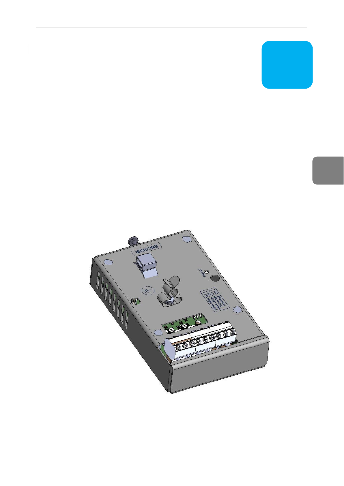
INTRODUCTION.....................................................................................................................................7
Encoder board specifications ...............................................................................................................8
LED indicators......................................................................................................................................8
CONNECTION TO THE DRIVE..............................................................................................................9
Connectors description and LED indicators........................................................................................10
Connection drawings..........................................................................................................................12
COMMISSIONING ................................................................................................................................13
Parameters setting .............................................................................................................................13
Visualization parameters....................................................................................................................14
Summary of MODBUS addresses......................................................................................................14
FAULTS AND WARNINGS LIST..........................................................................................................15
Description of Fault list:......................................................................................................................15
Troubleshooting..................................................................................................................................15

POWER ELECTRONICS
SD750
SAFETY SYMBOLS
5
EN
SAFETY SYMBOLS
Always follow safety instructions to prevent accidents and potential hazards from occurring.
In this manual, safety messages are classified as follows:
Other symbols used in this manual for safety messages are the following:
WARNING
Identifies potentially hazardous situations where dangerous voltage may be
present, which if not avoided, could result in minor personal injury, serious
injury or death.
Be extremely careful and follow the instructions to avoid the risk of electrical
shocks.
CAUTION
Identifies potentially hazardous situations, which if not avoided, could result
in product damage, or minor or moderate personal injury.
Read the message and follow the instructions carefully.
NOTICE
Identifies important measures to take in order to prevent damage equipment
and warranty lost, as well as encouraging good use and environmental
practices.
Hot surface. Be careful and follow the instructions to avoid burns and personal injuries.
Risk of fire. Be careful and follow the instructions to prevent causing an unintentional fire.
Caution, risk of electric shock. Energy storage timed discharge. Wait for the indicated
time to avoid electrical hazards.
Caution, risk of hearing damage. Wear hearing protection.

SD750
POWER ELECTRONICS
6
SAFETY INSTRUCTIONS
SAFETY INSTRUCTIONS
IMPORTANT!
Read carefully this manual to maximize the performance of the product and to ensure its safe installation
and use.
In order to appropriately use the drive, please, follow all instructions described in the Hardware and
Installation Manual which refer to transportation, installation, electrical connection and commissioning of
the equipment.
For maintenance operations, follow the instructions from the Maintenance Manual.
Power Electronics accepts no responsibility for any damages resulting from incorrect use of equipment.
CAUTION
Read carefully the Hardware and Installation Manual, the Maintenance Manual and all documentation
related to the drive to guarantee its safe use and avoid the risk of personal injuries and damages to the
equipment.
Ensure compliance with local and national regulations of the installation site.
NOTICE
CAUTION IN CONNECTIONS
Use conductive paste between plates in every electrical connection. Otherwise, resistance will
increase and an overheat in the contact zone of the conductors may occur.

POWER ELECTRONICS
SD750
INTRODUCTION
7
EN
INTRODUCTION
SD750 drives are compatible with several optional boards:
•Communication boards (Ethernet/IP, Profinet, CANopen…).
•Encoder board.
•Digital and analog I/O expansion boards.
•Optical fiberboard
…among others. Up to three optional boards can be connected, maximum two of the same type.
This manual focuses on the optional encoder board. The encoder board allows the SD750 to be
connected to an encoder to measure the speed of the motor it controls. This card has two channels for the
connection of this encoder, which will be essential to have for closed-loop controls.
1

SD750
POWER ELECTRONICS
8
INTRODUCTION
Encoder board specifications
•Device type: Encoder.
•Outputs for powering each encoder, programmable from 5VDC to 24VDC.
•Optical insulation between the encoder and the control board.
•Inputs for Channel A, /A, Channel B, /B and Channel Z, /Z (zero pass detection).
•Differential or ‘single-ended’ type inputs.
•Supports encoders with open collector output, voltage and ‘push-pull’.
LED indicators
The encoder expansion board includes 1 led indicator (status) that provides information about the
operation of the card. See section "Connectors description and led indicators" for more information.

POWER ELECTRONICS
SD750
CONNECTION TO THE DRIVE
9
EN
CONNECTION TO THE DRIVE
The encoder expansion board can be connected directly, through the connector on its back side, to any of
the three expansion connectors of the SD750 drive central control board. Once connected, it allows
integrating an encoder through its connection to the expansion card.
CAUTION
Power Electronics’ SD750 drives operate with high electric energy.
Make sure the power supply has been disconnected and wait for at least 10 minutes to guarantee that
DC bus is discharged before installing the expansion board. Otherwise, there is a risk of personal injuries
or accidents.
2

SD750
POWER ELECTRONICS
10
CONNECTION TO THE DRIVE
Connectors description and LED indicators
The LED indicators on the encoder expansion board provide information about the board and
communication status.
The encoder expansion board has a single green LED that indicates if the own board is powered, and
whose frequency changes according to the system operating status.
All led statuses are explained in the following table:
LED
COLOR / FREQUENCY
DESCRIPCIÓN
STATUS
Green, normal blinking
The system is operating correctly 1.
Red, slow blinking
The board cannot establish communication with the network
controller or initialize the protocol.
Red, fast blinking
The board cannot establish communication with the SD750
central board.
There are two connectors on the encoder board: one is for connecting the encoder board to the inverter
control board (located at the back side of the board); the other connector is used for connecting the motor
encoder, it is located at the front side and it consists of 9 terminals. Each terminal description of the latter
connector is shown in the following table.
1
When we state that the system operates correctly, it means that the communication between the expansion board, the
network controller and the central SD750 microcontroller is correct. This does not mean, however, that the
communication with the PLC is correct.

POWER ELECTRONICS
SD750
CONNECTION TO THE DRIVE
11
EN
TERMINAL
DESCRIPTION
+5V
Input voltage for Motor encoder +5VDC
+24V
Alimentación del encoder +24VDC
GND
Common terminal for input voltage of Motor encoder
Z-
Channel Z (inverse polarity).
Z+
Channel Z
B-
Channel B (inverse polarity)
B+
Channel B
A-
Channel A (inverse polarity)
A+
Channel A
The expansion card includes three rotatory switches where each one corresponds to a different
channel (A, B or Z). These switches have 4 alternative configurations, according to the encoder type:
TERMINAL
DESCRIPTION
HTL diferential
Differential encoder, +24VDC signal
TTL diferential
Differential encoder, +5VDC signal
HTL single ended
Single-ended encoder, +24VDC signal
TTL single ended
Single-ended encoder, +5VDC signal

SD750
POWER ELECTRONICS
12
CONNECTION TO THE DRIVE
Connection drawings
The following section shows two encoder wiring examples according to the input voltage andthe output
type of the encoder.
Example 1
Connection of motor encoder powered at 24V with differential output.
Example 2
Connection of motor encoder powered at 5V with ‘single-ended’ output.

POWER ELECTRONICS
SD750
COMMISSIONING
13
EN
COMMISSIONING
The encoder expansion board allows connecting an encoder to the drive SD750 in order to measure the
controlled engine speed.
The following steps must be followed:
1. After stopping and de-energizing the drive, connect the expansion card to the connector of the
equipment prepared for the expansion cards that are free.
2. Check that the communication with the SD750 is correct (by displaying group G18). See that the
encoder expansion card status is activated in the group.
3. Connect the encoder to the expansion board.
4. Select in the rotatory switch of each channel the encoder mode according to its options.
5. Enable encoder (parameter G18.1)
6. Select the number of pulses per revolution with parameter G18.2.
7. Select the control mode to be applied to the motor
Parameters setting
Up next, the relevant parameters are summarized. For details about the range of values and Modbus
addresses, refer to the Software and Programming Manual for SD750 drives.
Subgroup G18: Encoder
Group G18 of the SD750 drive allows configuring and displaying the status of the encoder expansion
board.
The parameters to be configured are the following
•G18.1: Allows enabling/disabling encoder.
•G18.2: Pulses per revolution. They can be adjusted according to the specified connected
encoder.
Screen
Range
Function
Set on
RUN
G18.1 Enable
encoder = No
No
Yes
Allows enabling or disabling the encoder.
OPT.
FUNCTION
No
The Encoder is enabled
Yes
The Encoder is disabled
NO
G18.2 Encoder PPR =
1024 PPR
0 to 8191 PPR
Allows configuring the pulses per encoder revolution.
Available if [G18.1 = Yes].
NO
3

SD750
POWER ELECTRONICS
14
COMMISSIONING
Visualization parameters
Up next, the relevant visualization parameters are summarized. For details about the range of values
and Modbus addresses, refer to the Software and Programming Manual for SD750 drives.
•Group SV1: Motor visualization
oSV1.17: Encoder speed = 0 rpm. Shows the real speed measured by the encoder.
Screen
Units
Description
SV1.17 Encoder speed = 0 rpm
rpm
Real speed measured by the encoder.
Visible if [G18.1 = Yes].
•Group SV9.1: Motor registers
oSV9.1.16: Encoder pulses = 0. Shows the pulse count of the encoder.
oSV9.1.17: Encoder speed = 0 rpm. Shows the speed seen by the encoder.
Screen
Units
Description
SV9.1.16 Encoder pulses = 0
-
Shows the pulse count of the Encoder.
SV9.1.17 Encoder speed = 0 rpm
RPM
Shows the speed seen by the Encoder.
Summary of MODBUS addresses
Visualization Parameters
Parameter
Screen
Description
Address
Modbus Range
SV1.16
Encoder pulses = 0
Shows the pulses per revolution of
the encoder.
42020
Real Value = Modbus Value
SV1.17
Encoder speed = 0 rpm
Real speed measured by the
encoder.
42021
Real Value = Modbus Value
SV9.1.16
Encoder pulses = 0
Shows the pulse count of the
Encoder.
42470
Real Value = Modbus Value
Programming Parameters
Parameter
Screen
Address
Range
Modbus Range
Access [1]
G18.1
Enable encoder = No
40581
No
Yes
0 to 1
No
G18.2
Encoder PPR = 1024 PPR
40582
0 to 8191 PPR
0 to 8191
Si

POWER ELECTRONICS
SD750
FAULTS AND WARNINGS LIST
15
EN
FAULTS AND WARNINGS LIST
Please, consult the full list of fault and warning messages in the Software and Programming Manual for
SD750 drives.
Description of Fault list:
DISPLAY
DESCRIPTION
F36: Encoder card com.
There is a communication problem between the encoder card and central control.
F37: Encoder card timeout
The encoder card is not detected.
F38: Encoder
Incorrect encoder measurement while working in closed loop.
Troubleshooting
DISPLAY
POSSIBLE CAUSE
ACTIONS
F36: Encoder card com.
There is a communication problem between the
encoder card and central control.
Remove drive power supply and turn it on again.
Check the encoder configuration.
F37: Encoder card
timeout
The encoder card is not detected.
Verify the card is connected correctly.
F38: Encoder
Wrong encoder reading
Check the encoder wiring and its power.
4


Other manuals for SD750 Series
9
Table of contents
Other Power Electronics Media Converter manuals
Popular Media Converter manuals by other brands

madVR
madVR Envy quick start guide

Avenview
Avenview C-VGA-HDM user guide

Absolute Process Instruments
Absolute Process Instruments DuoPak APD 2016 manual

Baumer
Baumer HUBNER BERLIN DeviceNet HMG 10 Mounting and operating instructions

IONODES
IONODES ATOMAS-DUO-HDMI user manual

Horizon Fitness
Horizon Fitness LampizatOr user manual