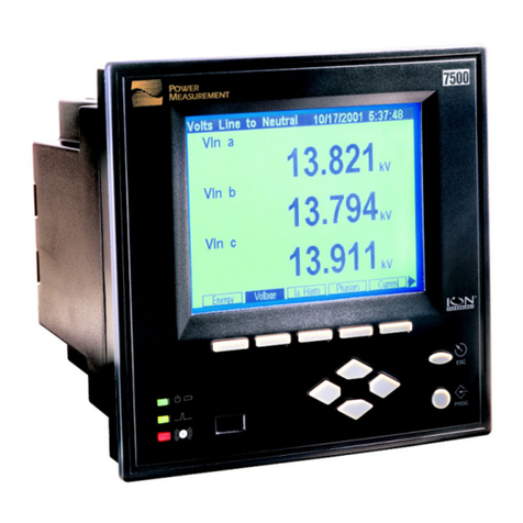
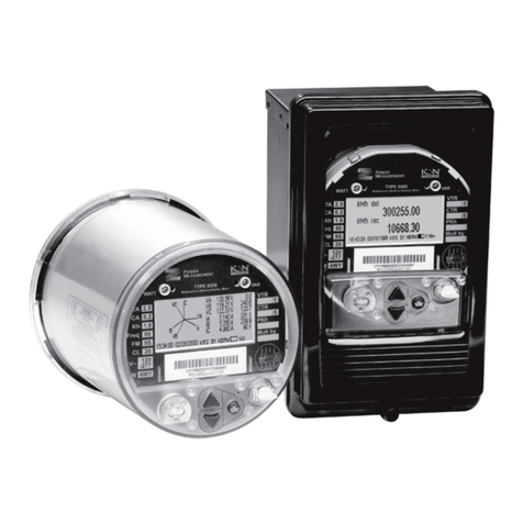
Power Measurement ION 7700 User manual


3
Danger
This symbol indicates the presence of dangerous voltage within and outside the product enclosure
that may constitute a risk of electric shock, serious injury or death to persons if proper precautions
are not followed.
Caution
This symbol alerts the user to the presence of hazards that may cause minor or moderate injury to
persons, damage to property or damage to the device itself, if proper precautions are not followed.
Note
This symbol directs the user’s attention to important installation, operating and maintenance
instructions.
Service Considerations
Servicing the ION 7700 meter should only be performed by qualified, competent personnel that have appropriate
training and experience with high voltage and current devices. The meter must be serviced in accordance with all Local
and National Electrical Codes.
DANGER
Failure to observe the following instructions may result in severe injury or death.
During normal operation of the ION 7700 meter, hazardous voltages are present on its terminal strips,
and throughout the connected potential transformer (PT), current transformer (CT), digital (status) input,
control power and external I/O circuits. PT and CT secondary circuits are capable of generating lethal
voltages and currents with their primary circuit energized. Follow standard safety precautions while per-
forming any installation or service work (i.e. removing PT fuses, shorting CT secondaries, etc).
The terminal strips on the meter base should not be user-accessible after installation.
Do not use digital output devices for primary protection functions. These include applications where the
devices perform energy limiting functions or provide protection of people from injury. Do not use the ION
7700 in situations where failure of the devices can cause injury or death, or cause sufficient energy to be
released that can start a fire. The meter can be used for secondary protection functions.
Do not HIPOT/Dielectric test the digital (status) inputs, digital outputs, or communications terminals. Refer
to the label on the ION 7700 meter for the maximum voltage level the device can
withstand.
CAUTION
Observe the following instructions, or permanent damage to the meter may occur.
The ION 7700 meter offers a range of hardware options that affect input ratings. The ION 7700 meter’s
serial number label lists all equipped options. Applying current levels incompatible with the current inputs
will permanently damage the meter.
The ION 7700 meter’s chassis ground must be properly connected to the switchgear earth ground for the
noise and surge protection circuitry to function correctly. Failure to do so will void the warranty.
Terminal screw torque: Barrier-type (current, voltage, and relay terminal screws: 1.35 Nm (1.00 ft-lbf)
max. Captured-wire type (digital inputs/outputs, communications, power supply: 0.90 Nm
(0.66 ft.lbf) max.
FCC Notice
This equipment has been tested and found to comply with the limits for a Class A digital device, pursuant to Part 15
of the FCC Rules. These limits are designed to provide reasonable protection against harmful interference when the
equipment is operated in a commercial environment. This equipment generates, uses, and can radiate radio
frequency energy and, if not installed and used in accordance with the instruction manual, may cause harmful
interference to radio communications. Operation of this equipment in a residential area is likely to cause harmful
interference in which case the user will be required to correct the interference at his own expense.

4
The Ringer Equivalence Number (REN) for the ION 7700 optional internal modem is 0.6. Connection to the ION
7700 internal modem should be made via an FCC Part 68 compliant telephone cord (not supplied). The ION 7700
cannot be used on a public coin phone service or party line services.
Network Compatibility Notice for the Internal Modem
The internal modem in meters equipped with this option is compatible with the telephone systems of most countries
in the world, with the exception of Australia and New Zealand. Use in some countries may require modification of the
internal modem’s initialization strings. If problems using the modem on your phone system occur, please contact
Power Measurement Technical Support
Standards Compliance
International The 7700 ION is operable under Pollution Degree II
Measuring inputs comply with Installation Category III
Power Supply inputs comply with Installation Category II
All inputs pass ANSI/IEEE C37.90-1989 surge withstand and fast transient tests
UL UL listed UL 3111-1
CSA CAN/CSA-C22.2 No.142-M1987 and CAN/SCSA-C22.2 No.1010.1-95
LVD Registered under CB Scheme to EN61010-1:1995
EMC EN50081-2:1994 and EN50082-2:1995
FCC Part 15 of FCC Rules for a Class A Digital Device
Limitation of Liability
Power Measurement Ltd. (“Power Measurement”) reserves the right to make changes in the device or its specifications
identified in this
document without notice. Power Measurement advises customers to obtain the latest version of the
device specifications before placing orders to verify that the information being relied upon by the customer is current.
Regardless of whether any remedy set forth herein fails of its essential purpose, except to the extent the following
limitation is prohibited by applicable law, Power Measurement shall not, in any event or under any legal claim or
theory (whether based on contract, indemnity, warranty, tort (including negligence and strict liability) or otherwise), be
liable to the original purchaser or any other person or entity for special, indirect, incidental, punitive, liquidated, special
or consequential damages whatsoever with respect to any purchased product, including, without limitation, business
interruption, loss of use, profit or revenue, even if Power Measurement has been advised of the possibility of such
damages. To the extent that a limitation or exclusion of consequential damages are prohibited by applicable law, then
Power Measurement’s liability shall be limited to twice the amount of the relevant purchased product. Not to limit the
foregoing, a) Power Measurement shall not be liable for any claim (other than a claim solely for the breach of one of
the above Warranties that is made in accordance with the above described procedures) made by the original
purchaser, its employees, agents, or contractors for any loss, damage, or expense incurred due to, caused by, or
related to any purchased product; and b) the above Warranties are the original purchaser's exclusive remedy and
Power Measurement hereby expressly disclaims all other warranties, express or implied, including, without limitation,
warranties of non-infringement and the implied warranties of merchantability and fitness for a particular purpose.
These limited Warranties shall not apply to any product that has been subject to alteration, accident, misuse, abuse,
neglect or failure to exactly follow Power Measurement's instructions for operation and maintenance. Any technical
assistance provided by Power Measurement's personnel or representatives in system design shall be deemed to be a
proposal and not a recommendation. The responsibility for determining the feasibility of such proposals rests with the
original purchaser and should be tested by the original purchaser. It is the original purchaser’s responsibility to
determine the suitability of any product and associated documentation for its purposes. The original purchaser
acknowledges that 100% "up" time is not realizable because of possible hardware or software defects. The original
purchaser recognizes that such defects and failures may cause inaccuracies or malfunctions. Only the terms expressed
in these limited Warranties shall apply and no distributor, corporation or other entity, individual or employee of Power
Measurement or any other entity is authorized to amend, modify or extend the Warranties in any way.
The information contained in this document is believed to be accurate at the time of publication, however, Power
Measurement assumes no responsibility for any errors which may appear here and reserves the right to make changes
without notice.
Power Measurement, ION, ION Enterprise, MeterM@il, WebMeter and “smart energy everywhere” are either
registered trademarks or trademarks of Power Measurement. All other trademarks are property of their respective
owners.
Covered by one or more of the following patents:
U.S. Patent No's 6751562, 6745138, 6737855, 6694270, 6671654, 6671635, 6687627, 6615147, 6611922,
6611773, 6563697, 6493644, 6397155, 6186842, 6185508, 6000034, 5995911, 5828576, 5736847,
5650936, D459259, D458863, D443541, D439535, D435471, D432934, D429655, D429533, D427533.
5
Contents
Before You Begin . . . . . . . . . . . . . . . . . . . . . . . . . . . . . . . . . . . . . . . . 6
Removing and Replacing the Meter Lid (Xpress Card) . . . . . . . . . . . . . . 7
Replacing the Comm Card . . . . . . . . . . . . . . . . . . . . . . . . . . . . . . . . . . 8
Using the RM Key . . . . . . . . . . . . . . . . . . . . . . . . . . . . . . . . . . . . . . . . 9
Installing the Terminal Strip Cover . . . . . . . . . . . . . . . . . . . . . . . . . . . 11
Installing the ION 7700 Adapter Plate . . . . . . . . . . . . . . . . . . . . . . . . 12
Replacing the MGT Keypad . . . . . . . . . . . . . . . . . . . . . . . . . . . . . . . . 13

6
Before You Begin
DANGER
During normal operation of the meter, hazardous voltages are present which
can cause severe injury or death. These voltages are present on the terminal
strips of the device and throughout the connected potential transformer (PT),
current transformer (CT), status input, relay, and control power circuits. Only
qualified, properly trained personnel should perform installation and
servicing.
Before performing any service on the meter:
Familiarize yourself with the steps in this guide.
Read the safety precautions on the “Service Considerations” page.
Complete the following steps before attempting any retrofits.
1. Turn off ALL power to the meter.
2. Open all PT fuses (or direct voltage input fuses).
3. Close all CT shorting blocks.
4. Ensure that all cables still connected to the meter are NOT live.
CAUTION
The components inside the meter are extremely sensitive to electrostatic
discharge. To prevent damage to the unit, wear an anti-static wrist strap at
all times when working inside the unit. Failure to use proper equipment
during servicing will void the ION 7700 meter’s warranty.
Recommended Tools
Phillips screwdriver
Flat-head screwdriver
Adjustable wrench or socket wrench set
Wire cutter
Anti-static wrist strap or similar protection

7
Removing and Replacing the Meter Lid (Xpress Card)
Removing the meter lid/Xpress Card
1. Using #2 Phillips screwdriver, remove the four screws from the ION
7700 meter lid. If equipped with an Xpress Card, it is mounted onto the
meter lid.
2. Lift the cover straight up to unplug the Xpress card from the main board
inside the meter.
Replacing the meter lid/Xpress Card
1. Line up the Xpress Card edges with the grooves in the meter chassis.
Slide down until the edges catches the slot in the main board. Press
firmly to plug the card in.
2. Secure the lid onto the chassis using the four screws.

8
Replacing the Comm Card
These instructions apply to the standard communications card (with or
without the internal modem).
1. Remove the meter lid/Xpress Card. The comm card (standard or
modem) is located beside the power supply unit.
2. Grasp the comm card and pull straight up to remove it.
3. Ensuring proper orientation, slide the replacement comm card into its slot
and press down to plug it in.
4. Replace the meter lid/Xpress Card.

9
Using the RM Key
The Revenue Meter Programming Key (RMKey) is a device which plugs into
the ION 7700 revenue meter and disables its security systems in order to
facilitate programming. This key is typically used by utility meter shop
personnel who want to program a revenue meter in-house. The RMKey can
be used on revenue class ION 7700 meters (-RM, -RMANSI or -RMICAN).
The RMKey consists of a 3" x 5" circuit board with a polarized connector (to
prevent improper mating). The connector protrudes from the component
side.
Inserting the RMKey
1. Remove the meter lid.
2. The RMKey plugs into the same socket as the Auxiliary Analog Input Card.
If your ION 7700 meter is equipped with an Analog Input Card, carefully
remove it first, and set it aside on a static-protected surface.
3. Hold the RMKey by its sides, with the component side facing toward the
side closest to the MGT (DB9) connector. Slide the edge of the card along
the slot inside the chassis and lower the card toward the VAUX slot.
4. Line up the connector with the socket and plug the RMKey firmly into
place.
5. Replace the meter lid/Xpress Card.
CAUTION
Failure to plug the Xpress Card back into the meter will result in loss of
configuration data
6. Power up the ION 7700 meter and proceed with programming/
configuration. Note that you cannot delete "locked" modules, even when
the RMKey is inserted.

10
Removing the RMKey
1. Remove or disable any power source connected to the meter.
2. Unplug and remove the RMKey to re-enable all meter security systems.
3. If the meter is equipped with the Aux Card, applicable, plug it back into
the meter.
4. Replace the meter lid/Xpress Card.
5. Install the lead/wire seals through the sealing tabs.

11
Installing the Terminal Strip Cover
The terminal strip cover provides an insulation barrier for the wiring
terminals. Complete the wiring to the ION 7700 meter’s terminal strip, then:
1. Place the terminal strip cover over the terminal strip, arranging the wires
so they rest in the slots of the terminal strip cover. Use the mounting
screws to secure the terminal strip cover to the meter’s first and third vent
holes.
2. If a tamperproof seal is required, use the optional sealing can assembly.
Secure the sealing can (C) to the terminal cover (A) and meter chassiss
using the mounting screw (B). Insert the ball bearing (D), then feed the
sealing wire (E) through the hole to secure the ball bearing, and seal the
wire ends.
Assembled sealing kit

12
Installing the ION 7700 Adapter Plate
The ION 7700 adapter plate allows the ION 7700 meter base or MGT to be
mounted onto an existing ACM 3000 series mounting hole.
Step 1: Remove the existing 3000 series meter
Step 2: Resize the panel cut-out
Cut away the two areas identified in the following diagram.
Step 3: Attach the adapter plate to the meter
Use the four nuts to attach the MGT to the Adapter Plate. Place the MGT and
attached Adapter Plate into the mounting hole. Use the four hex nuts and lock
washers to secure the plate and meter to the panel.
If you want to attach your 7700 ION behind the MGT, screw the four
aluminum spacers to the four studs provided, then mount the 7700 ION on
the spacers.
186 mm [7.32“]
Panel
49 mm
[1.94“]
135 mm
[5.30“]
49 mm
[1.94“]
31 mm
[1.24“]
Existing cut-out
for 3000 series
meter.
Cut away
Cut away

13
Replacing the MGT Keypad
1. Use a #1 Phillips screwdriver to remove the six screws from the back of
the MGT.
2. Remove the display and backlight cables.

14
3. Use a #2 Phillips screwdriver to remove the four MGT circuit board
screws.
4. Lift up the MGT circuit board.
5. Unplug the keypad connector.

15
6. Use a small flat screwdriver to pry the corner of the keypad loose.
7. Peel the keypad off the faceplate.
8. The supplied adaptor is required to connect the new keypad connector to
the old style header on the MGT circuit board.

16
9. Peel adhesive backing from underneath the keypad connector. This
prevents the keypad from lifting up along the edge at this location.
10. Peel the remaining adhesive backing from the keypad. Be careful not to
contaminate the adhesive or the LCD window with your fingers. Holding
the keypad connector down with one hand, the adhesive backing can be
peeled away without touching the back of the keypad.
11. Feed the new keypad connector through the slot in the faceplate.

17
12. Align the bottom corners of the keypad and attach to the faceplate.
13. Align the top corners of the keypad. Apply pressure over the entire
surface of the keypad to firmly attach it to the faceplate.
14. Attach the adapter to the keypad connector, as shown, with the white
connector facing you. Insert the keypad tail completely inside the adapter
connector.

18
15. Lock the connector in place. Pull gently to make sure it is locked firmly;
the adapter should not slip.
16. Attach the keypad adapter to the MGT circuit board as shown and make
sure the connector is completely seated.
17. Reposition MGT circuit board onto the four standoffs.

19
18. Reattach the backlight connector; this connector is keyed and can be
plugged in only the correct way.
19. Reattach display connector; be careful to line up the header properly.
20. Replace the four screws to fasten the MGT circuit board to the faceplate.
Replace the back cover, and fasten the six screws. Your MGT is now ready

For further assistance
please contact us at:
Worldwide Headquarters
2195 Keating Cross Road
Saanichton, BC
Canada V8M 2A5
Tel: 1-250-652-7101
Fax: 1-250-652-0411
Email: [email protected]
www.pwrm.com
© 2004 Power Measurement
Printed in Canada
MRP: 70050-0199-00
Revision Date: Oct 4, 2004
Table of contents
Other Power Measurement Measuring Instrument manuals

Power Measurement
Power Measurement 3300 ACM User manual

Power Measurement
Power Measurement 3300 ACM User manual

Power Measurement
Power Measurement ION 8300 User manual

Power Measurement
Power Measurement ION 8300 User manual

Power Measurement
Power Measurement 7330 ION User manual

Power Measurement
Power Measurement 3720 ACM User manual

Power Measurement
Power Measurement ION 8000 Series User manual

Power Measurement
Power Measurement 3710 ACM User manual

Power Measurement
Power Measurement 7500 User manual

Power Measurement
Power Measurement ION 8800 User manual