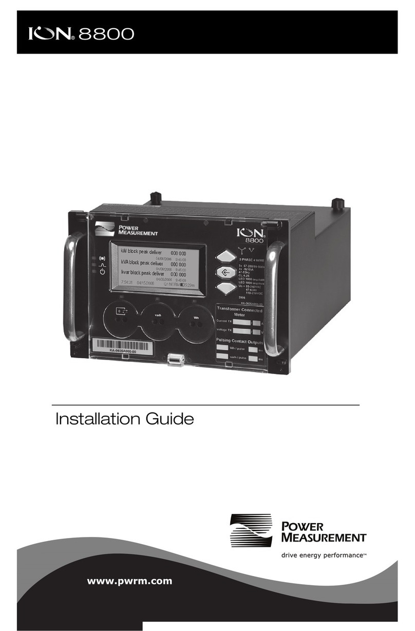
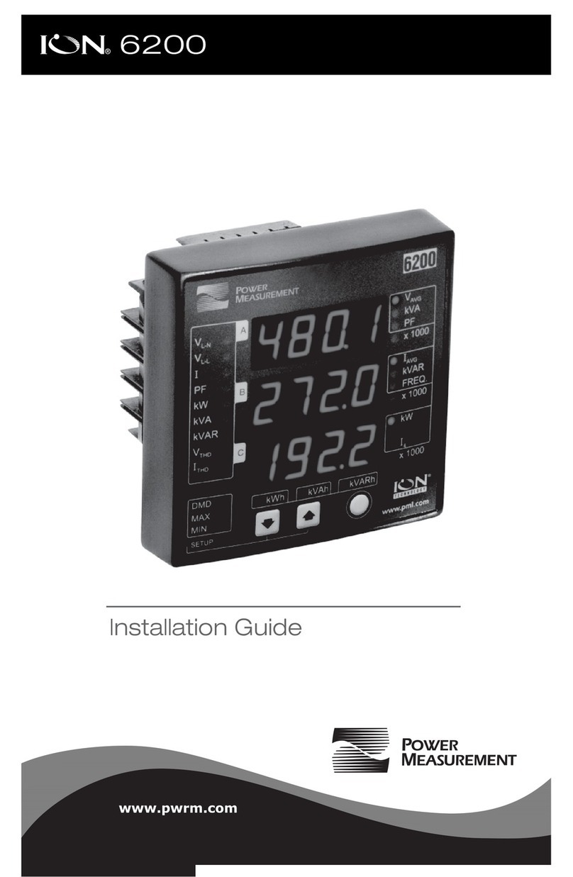
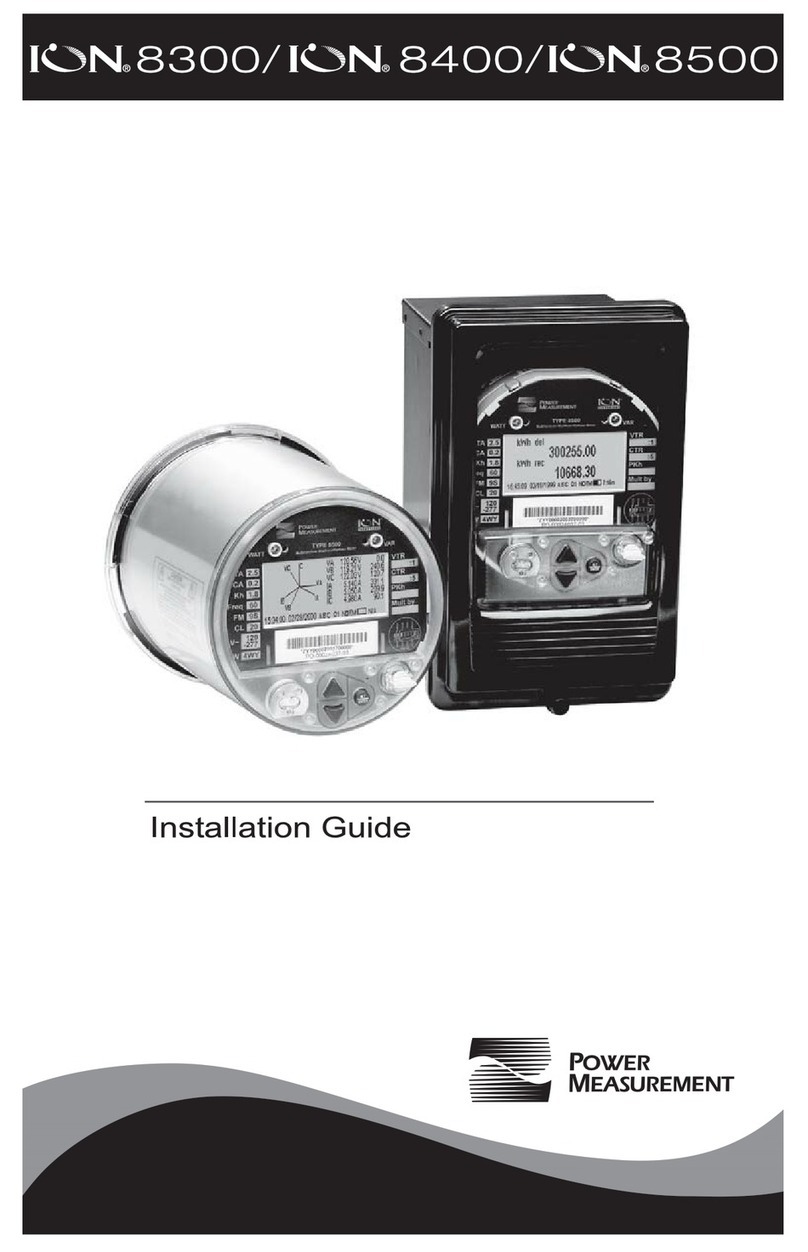
Power Measurement ION 8000 Series User manual


3
Danger
This symbol indicates the presence of dangerous voltage within and outside the product enclosure that
may constitute a risk of electric shock, serious injury or death to persons if proper precautions are not
followed.
Caution
This symbol alerts the user to the presence of hazards that may cause minor or moderate injury to
persons, damage to property or damage to the device itself, if proper precautions are not followed.
Note
This symbol directs the user’s attention to important installation, operating and maintenance instructions.
Retrofit Considerations
Retrofit and maintenance of the ION 8000 series meter should only be performed by qualified, competent personnel
that have appropriate training and experience with high voltage and current devices. The meter must be installed in
accordance with all Local and National Electrical Codes.
DANGER
Failure to observe the following instructions may result in severe injury or death.
During normal operation of the ION 8000 series meter, hazardous voltages are present on its terminal
strips, and throughout the connected potential transformer (PT), current transformer (CT), digital (status)
input, control power and external I/O circuits. PT and CT secondary circuits are capable of generating
lethal voltages and currents with their primary circuit energized. Follow standard safety precautions while
performing any installation or service work (i.e. removing PT fuses, shorting CT secondaries, etc).
The terminal strips on the meter base should not be user-accessible after installation.
Do not use digital output devices for primary protection functions. These include applications where the
devices perform energy limiting functions or provide protection of people from injury. Do not use the ION
8000 series in situations where failure of the devices can cause injury or death, or cause sufficient energy
to be released that can start a fire. The meter can be used for secondary protection functions.
Do not HIPOT/Dielectric test the digital (status) inputs, digital outputs, or communications terminals. Refer
to the label on the ION 8000 series meter for the maximum voltage level the device can
withstand.
CAUTION
Observe the following instructions, or permanent damage to the meter may occur.
The ION 8000 series meter offers a range of hardware options that affect input ratings. The ION 8000
series meter’s serial number label lists all equipped options. Applying current levels incompatible with the
current inputs will permanently damage the meter. This document provides retrofit instructions applicable
to each hardware option.
The ION 8000 series meter’s chassis ground must be properly connected to the switchgear earth ground
for the noise and surge protection circuitry to function correctly. Failure to do so will void the warranty.
Terminal screw torque: Barrier-type (current, voltage, and relay terminal screws: 1.35 Nm (1.00 ft-lbf)
max. Captured-wire type (digital inputs/outputs, communications, power supply: 0.90 Nm
(0.66 ft.lbf) max.
FCC Notice
This equipment has been tested and found to comply with the limits for a Class A digital device, pursuant to Part 15
of the FCC Rules. These limits are designed to provide reasonable protection against harmful interference when the
equipment is operated in a commercial environment. This equipment generates, uses, and can radiate radio
frequency energy and, if not installed and used in accordance with the instruction manual, may cause harmful
interference to radio communications. Operation of this equipment in a residential area is likely to cause harmful
interference in which case the user will be required to correct the interference at his own expense.

4
The Ringer Equivalence Number (REN) for the ION 8000 series optional internal modem is 0.6. Connection to the
ION 8000 series internal modem should be made via an FCC Part 68 compliant telephone cord (not supplied). The
ION 8000 series cannot be used on a public coin phone service or party line services.
Network Compatibility Notice for the Internal Modem
The internal modem in meters equipped with this option is compatible with the telephone systems of most countries
in the world, with the exception of Australia and New Zealand. Use in some countries may require modification of the
internal modem’s initialization strings. If problems using the modem on your phone system occur, please contact
Power Measurement Technical Services
Standards Compliance
Limitation of Liability
Power Measurement Ltd. (“Power Measurement”) reserves the right to make changes in the device or its
specifications identified in this
document without notice. Power Measurement advises customers to obtain the
latest version of the device specifications before placing orders to verify that the information being relied upon
by the customer is current.
Regardless of whether any remedy set forth herein fails of its essential purpose, except to the extent the following
limitation is prohibited by applicable law, Power Measurement shall not, in any event or under any legal claim
or theory (whether based on contract, indemnity, warranty, tort (including negligence and strict liability) or
otherwise), be liable to the original purchaser or any other person or entity for special, indirect, incidental,
punitive, liquidated, special or consequential damages whatsoever with respect to any purchased product,
including, without limitation, business interruption, loss of use, profit or revenue, even if Power Measurement has
been advised of the possibility of such damages. To the extent that a limitation or exclusion of consequential
damages are prohibited by applicable law, then Power Measurement’s liability shall be limited to twice the
amount of the relevant purchased product. Not to limit the foregoing, a) Power Measurement shall not be liable
for any claim (other than a claim solely for the breach of one of the above Warranties that is made in accordance
with the above described procedures) made by the original purchaser, its employees, agents, or contractors for
any loss, damage, or expense incurred due to, caused by, or related to any purchased product; and b) the above
Warranties are the original purchaser's exclusive remedy and Power Measurement hereby expressly disclaims all
other warranties, express or implied, including, without limitation, warranties of non-infringement and the
implied warranties of merchantability and fitness for a particular purpose.
These limited Warranties shall not apply to any product that has been subject to alteration, accident, misuse,
abuse, neglect or failure to exactly follow Power Measurement's instructions for operation and maintenance. Any
technical assistance provided by Power Measurement's personnel or representatives in system design shall be
deemed to be a proposal and not a recommendation. The responsibility for determining the feasibility of such
proposals rests with the original purchaser and should be tested by the original purchaser. It is the original
purchaser’s responsibility to determine the suitability of any product and associated documentation for its
purposes. The original purchaser acknowledges that 100% "up" time is not realizable because of possible
hardware or software defects. The original purchaser recognizes that such defects and failures may cause
inaccuracies or malfunctions. Only the terms expressed in these limited Warranties shall apply and no
distributor, corporation or other entity, individual or employee of Power Measurement or any other entity is
authorized to amend, modify or extend the Warranties in any way.
The information contained in this document is believed to be accurate at the time of publication, however, Power
Measurement assumes no responsibility for any errors which may appear here and reserves the right to make
changes without notice.
ION, ION Enterprise, ION Setup, ION Wire, PEGASYS, ION 6200, ION 7300, ION 7330, ION 7350, ION
7500, ION 7600, ION 7700, ION 8300, ION 8400, ION 8500, COM32, COM128, Vista, VIP, Designer,
Reporter, MeterM@il, WebMeter, EtherGate, ModemGate, Xpress Card, Feature Packs and "smart energy
everywhere" are either registered trademarks or trademarks of Power Measurement. All other trademarks are
property of their respective owners.
Covered by one or more of the following patents:
U.S. Patent No's 6563697, 6397155, 6186842, 6185508, 6000034, 5995911, 5828576, 5736847,
5650936, D459259, D458863, D435471, D432934, D429655, D429533.
Canadian Patent No's 2148076, 2148075, D97355, D97356.
Other patents pending.

5
ION 8000 Series Retrofit Instructions
These retrofit instructions contain the following sections. Your workflow may
not specifically coincide with the steps outlined below:
Socket Meter
“Accessing the Socket Meter’s PC Boards” on page 7
“Replacing the I/O Card” on page 10
“Replacing the Communications Card” on page 11
“Replacing the Power Supply Cards” on page 12
“Replacing the Display” on page 14
“Replacing the Plastic Cover” on page 15
Switchboard Meter
“Accessing the Switchboard Meter’s PC Boards” on page 16
“Replacing the Battery (Switchboard Meter)” on page 21
“Replacing the Case Jaws (Switchboard Meter)” on page 22
“Replacing the communications board (Switchboard Meter)” on page 23
“Replacing the I/O Card (Switchboard Meter)” on page 24
“Replacing the Display Cover (Switchboard Meter)” on page 25
“Replacing the Power Cable (Switchboard Meter)” on page 26
RMICAN Model
ION 8000 series socket and switchboard meters can be Industry Canada
certified for revenue metering in Canada. Different security options are
available, including a factory-sealed version.
CAUTION
Removing RMICAN factory seals to perform a retrofit may render your meter
non-compliant with Industry Canada certification.

6
Before You Begin
Familiarize yourself with the steps in this guide and read the safety
precautions presented on the “Retrofit Considerations” page.
DANGER
Ensure the meter has been unpowered for at least 10 minutes prior to
assembly. This ensures the meter capacitors contain no residual charge. The
disconnected meter retains all its configuration settings.
Recommended Tools
#1 and #2 Phillips screwdrivers
Precision flat-head screwdriver
Wire cutters / stripper
Needle nose pliers
Grounding wrist strap
Location of PC Boards
PCB removal and installation details are discussed in the next sections. Meter
board locations are the same for both Switchboard and Socket type meters.
CPU board
Display board
Communications board
Filter board
Analog board
Switcher board
Interlocked
inside meter
*Not shown: I/O board
Outage Dialback board

7
Accessing the Socket Meter’s PC Boards
Ensure the meter has been unpowered for at least 10 minutes prior to
disassembly. This ensures the meter capacitors contain no residual charge.
The disconnected meter retains all its configuration settings.
In each retrofit scenario, you must first remove the plastic cover and the shield
of the socket meter to access the circuit boards.
Remove the plastic cover
1. Remove the metallic base seal from the bottom of the meter.
2. With the meter on a non-skid surface, press the cover down and twist
counter-clockwise).
3. Lift the cover and remove.

8
Access the meter’s PCBs
4. Remove the two screws from the shield and lift the shield off the meter.
5. Disconnect the ground cable and remove the four case side screws.

9
6. Remove the side case cover and expose the meter cards.

10
Replacing the I/O Card
1. Remove the meter’s cover and shield by following the steps outlined in
“Accessing the Socket Meter’s PC Boards” on page 7.
2. Remove display board and expose the I/O card.
3. Disconnect all wire plugs at the front end of the I/O card by lifting locking
tabs with a fine point tool. Slide card out.
4. Insert new I/O card and connect wires in their corresponding sockets.
5. Re-insert the display board.
6. Re-place the cover with the four side screws (taking care not to pinch any
of the wiring) and connect the ground wire.
7. Re-insert the shield with its two screws.
8. Re-insert the cover by aligning the rim slots and press down, twisting
clockwise. Secure with new base seal provided.

11
Replacing the Communications Card
1. Remove the meter’s cover and shield by following the steps outlined in
“Accessing the Socket Meter’s PC Boards” on page 7.
2. Remove display board by gently prying tabs back, pulling straight up on
the display board.
NOTE
Attempting to remove the Display unit at an angle will damage its connector
on the CPU.
3. Slide out the I/O card, exposing the communications board.
4. Disconnect all wire plugs at the front end of the card by lifting locking tabs
with a fine point tool. Slide card out.
5. Insert new communications board and connect wires in their
corresponding sockets.
6. Re-insert the I/O card if applicable and the display board.
7. Re-place the cover with the four side screws (taking care not to pinch any
of the wiring) and connect the ground wire.
8. Re-insert the shield with its two screws.
9. Re-insert the cover by aligning the rim slots and press down, twisting
clockwise. Secure with new base seal provided.

12
Replacing the Power Supply Cards
1. Remove the meter’s cover and shield by following the steps outlined in
“Accessing the Socket Meter’s PC Boards” on page 7.
2. Remove the display board and slide out the I/O card (if applicable) and
the communications board, exposing the two power supply cards.
3. Disconnect and slide the top power supply card out slightly to clear its
header pins. Disconnect the side socket from the bottom power supply
(top card removed below for clarity only).

13
4. Slide out the power supply pair of boards.
5. Insert, as a pair, the new bottom power supply (connect to side socket)
and the top power supply (connect to the CPU board).
6. Re-insert the communications board, the I/O card (if applicable) and the
display board.
7. Re-place the cover with the four side screws (taking care not to pinch any
of the wiring) and connect the ground wire.
8. Re-insert the shield with its two screws.
9. Re-insert the cover by aligning the rim slots and press down, twisting
clockwise. Secure with new base seal provided.

14
Replacing the Display
1. Remove the meter’s cover and shield by following the steps outlined in
“Accessing the Socket Meter’s PC Boards” on page 7.
2. Remove display board by carefully prying tabs back and pulling straight
up. Angling the display board will damage the connector on the CPU.
3. Insert new display, ensuring proper orientation.
4. Re-place the cover with the four side screws (taking care not to pinch any
of the wiring) and connect the ground wire.
5. Re-insert the shield with its two screws.
6. Re-insert the cover by aligning the rim slots and press down, twisting
clockwise. Secure with new base seal provided.

15
Replacing the Plastic Cover
1. Remove the meter’s cover by following the three steps outlined in
“Remove the plastic cover” on page 7.
2. Remove the shield as outlined in “Access the meter’s PCBs” on page 8.
3. Insert new cover by aligning the rim slots and press down, twisting
clockwise.
4. Insert new base seal provided (optional).

16
Accessing the Switchboard Meter’s PC Boards
Ensure the meter has been unpowered for at least 10 minutes prior to
disassembly. This ensures the meter capacitors contain no residual charge.
The disconnected meter retains all its configuration settings.
In each retrofit scenario, you must first remove the meter from its switchboard
casing to access the circuit boards.
Remove the meter from its switchboard casing
1. Release the screw at the front bottom of the display cover and lift.
2. Expose the front of the meter.

17
3. Slide metal brackets a & b in the direction and final position shown.
4. Slide all teeth from the front of the switchboard into the open position.

18
5. Press the top of the meter down and pull out of switchboard.
Remove the meter from its switchboard frame
6. Mark the position of the six wires at the bottom of the assembly and
unscrew. Terminal tabs are copper; avoid stripping.

19
7. Disconnect white connector.
8. Remove the four screws holding the meter to the cage and remove cage.

20
9. Remove the two screws and release the bracket from the base of the
meter.
10. Remove the two screws from the side of the meter and pull out side panel
to expose the meter's boards.
This manual suits for next models
3
Table of contents
Other Power Measurement Measuring Instrument manuals

Power Measurement
Power Measurement 3720 ACM User manual

Power Measurement
Power Measurement ION 8300 User manual

Power Measurement
Power Measurement 7500 User manual

Power Measurement
Power Measurement 3300 ACM User manual

Power Measurement
Power Measurement ION 8800 User manual

Power Measurement
Power Measurement ION 8300 User manual

Power Measurement
Power Measurement ION 7700 User manual

Power Measurement
Power Measurement ION 6200 User manual

Power Measurement
Power Measurement 3710 ACM User manual

Power Measurement
Power Measurement 3300 ACM User manual