Power Probe INT500 User manual

INT500
User Manual / MANUAL DEL USUARIO
Manuel d'utilisation / Benutzer-Handbuch
使用者手冊 / 使用者手册 / ユーザー マニュアル
Руководство по использованию
Insulation Tester & Multimeter
EN
Comprobador de aislamiento y multímetro
ES
Testeur d’isolement et multimètre
FR
Isolationsprüfgerät und Multimeter
DE
絕緣測試儀和萬用電表
TC
绝缘测试仪和万用电表
SC
絶縁抵抗計&マルチメーター
JP
Мегаомметр и мультиметр
RU

INT500 EN
1
Introduction
WARNING
Safety Information
This Insulation Tester is an accurate, professional industry tool
for measuring ACV, DCV, Frequency, Low Pass Filter, Earth-
Bond Resistance, Capacitor, Insulation Resistance.
Understand and follow operating instructions carefully.
• If the equipment is used in a manner not specied by the
manufacturer, the protection provided by the equipment may
be impaired.
• Always use proper terminals, switch position, and range for
measurements.
• To reduce the risk of re or electric shock, do not use this
product around explosive gas or in damp locations.
• Verify the Meter operation by measuring a known voltage. If
in doubt, have the Meter serviced.
• Do not apply more than the rated voltage, as marked on
Meter, between terminals or between any terminal and earth
ground.
• To avoid false readings that can lead to electric shock and
injury, replace battery as soon as low battery indicator blinks /
appears.
• Avoid working alone so that assistance can be rendered.
• Do not use the Tester if the Tester is not operating properly or
if it is wet.
• Individual protective device must be used if hazardous live
parts in the installation where the measurement is to be
carried out could be accessible.
• Disconnect the test leads from the test points before changing
the position of the function rotary switch.
• Never connect a source of voltage when the function rotary
switch is not in voltage position.
• When using test leads or probes, keep your ngers behind
the nger guards.
• Use caution with voltages above 30Vac rms, 42 Vac peak, or
60Vdc. These voltages pose a shock hazard.
• Remove test lead from Meter before opening the battery door
or Meter case.

INT500 EN
2
• DO NOT USE the test leads when the internal white insulation
layer is exposed.
• DO NOT USE the test leads above maximum ratings of CAT.
Environment, voltage and current, that are indicated on the
probe and the probe tip guard cap.
• DO NOT USE the test leads without the probe tip guard cap
in CAT III and CAT IV environments.
• Probe assemblies to be used for MAINS measurements shall
be RATED as appropriate for MEASUREMENT CATEGORY
III OR IV according to IEC 61010-031 and shall have a
voltage RATING of at least the voltage of the circuit to be
measured.
• Only replace the blown fuse with the proper rating as
specied in this manual.
• Do not attempt a resistance measurement when the open
voltage is above the fuse protection rating. Suspected open
voltage can be checked with voltage function.
• Never attempt a voltage measurement with the test lead
inserted into the Ω input terminal.
• Disconnect circuit power and discharge all high-voltage
capacitors before testing resistance, continuity, or
capacitance.
INT500 EN
3
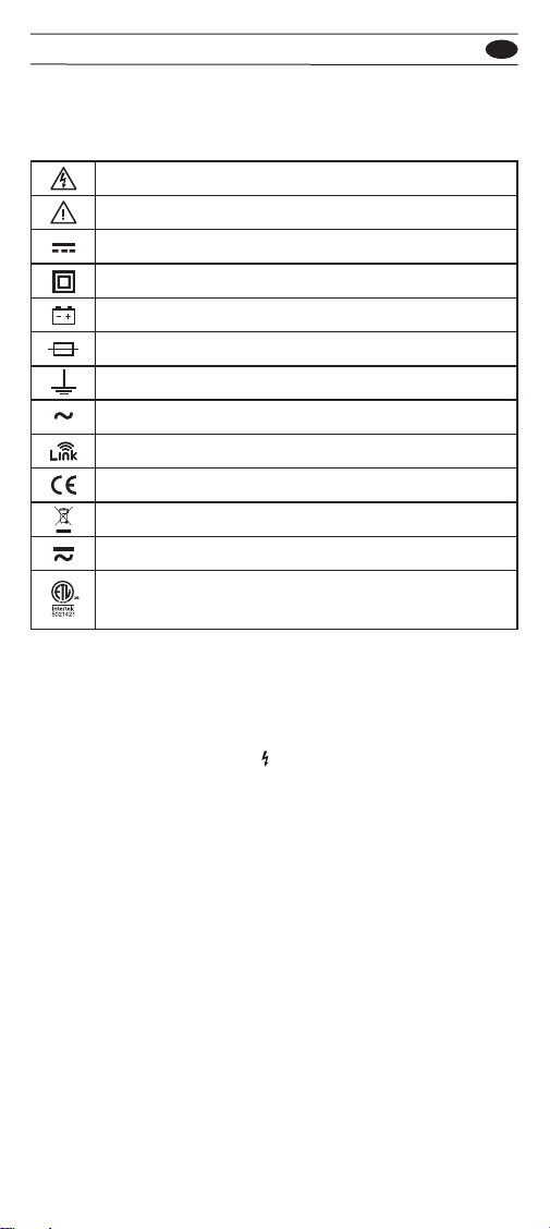
Symbols as marked on the Meter and
Instruction manual
Risk of electric shock
See instruction manual
DC measurement
Equipment protected by double or reinforced insulation
Battery
Fuse
Earth
AC measurement
Bluetooth
Conforms to EU directives
Do not discard this product or throw away.
Both direct and alternating current
This product CONFORMS TO UL STD 61010-1,
61010-2-034
Unsafe Voltage
Maintenance
Cleaning
To alert you to the presence of a potentially hazardous voltage,
when the Tester detects a voltage ≧30 V in insulation test, or
a voltage overload (OL), the ” “ symbol is displayed and High
voltage indicator is turned on.
Do not attempt to repair this Meter. It contains no user service
able parts. Repair or servicing should only be performed by
qualied personnel.
Periodically wipe the case with a dry cloth and detergent. Do
not use abrasives or solvents.
INT500 EN
4
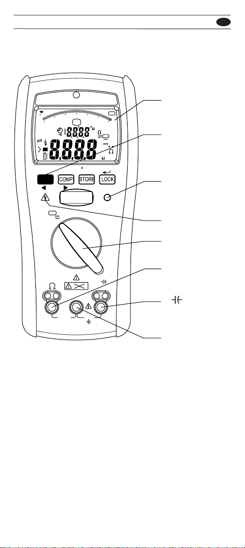
The Meter Description
Front Panel Illustration
Display
Function button
Pass indicator
High Voltage
indicator
Funtions & Power
On/O
Ω Input
V insulation
Input
Common Input
INSULATION
>660V
TEST
COM
600V
CAT IV
315mA
FUSED
5 Sec
Del Last
SETUP
RECALL
PI/DAR/t
PASS
V
LPF
OFF
TRUE RMS
L nk
100M
6100GK
10GK
1GK
100M
10M
1M
0
MEM
TEST
LOCK
AutoSense
RENPIDAR
COMPARE
m
A
MK
G
Hz
V
APO
LPF
R
V
A
MK
G
m
F
AC S
DC 0
V

INT500 EN
5
Measuring ACV/DCV : Auto sense function
Auto sense mode: The meter displays ACV or DCV whichever
is higher (>1V).
If the measured voltage is above 660Vac/dc, "> 660Vac/dc" will
appear on the display.
30V
LPF
INSULATION
COM
600
0
0
600
V
AC
Hz
V
DC
AutoSense
AutoSense
V
LPF
V
V
INT500 EN
6
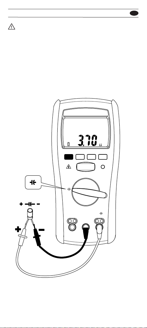
Measuring Capacitance
WARNING
When connecting the test leads to the DUT (Device Under
Test) connect the common test leads before connecting the live
leads; When removing the test leads, remove the test live leads
before removing the common test leads.
Don’t apply more than AC/DC 600V between the V-COM
terminals.
INSULATION
COM
COMP LOCK
F
STORE
V

INT500 EN
7
Wireless Link
L nk
L nk
L nk
The meter uses Bluetooth low energy (BLE) V5.0 wireless
technology to download the stored data. The open-air
communication range is up to 6m. The LINK icon of the
meter will freeze on LCD after the connection establishes
successfully.

INT500 EN
8
Switch Auto Voltage sense/ACV/DCV/LPF
function when the rotary switch is in voltage
position
Do not use the High Frequency Rejection (Low Pass Filter) to
verify the presence of hazardous voltages. Voltages greater
than what is indicated may be present. First, make a voltage
measurement without the lter to detect the possible presence
of hazardous voltage. Then select the lter function.
600
0
V
AC
Hz
AutoSense
600
0
LPF
AC
V
Press
600
0
V
AC
Hz
Press>2Sec
600
0
V
DC
Press
Press
Press
SETUP
SETUP
SETUP
SETUP
SETUP
WARNING

INT500 EN
9
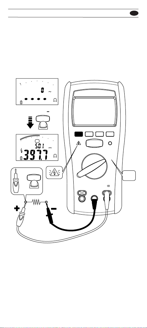
Measuring Earth-Bond Resistance (Continuity)
0
0
&
hold
Press
TEST
0
&
hold
Press
TEST
COMCOM
100 K
10K
1 K
100
10
1
0
100 K
10K
1 K
100
10
1
0
TEST
m
A
m
A
R
R
1. Before starting the test :
(a) The circuit under test must be completely de-energized.
(b) Check the fuse is good. See the chapter “Testing the
fuse”.
(c) Short the test leads before measurement, and press the
Function button to zero the wire resistance of probe. If
the wire resistance is <10Ω, the resistance oset value
will be saved, and the “->0<-” symbol will be displayed
on LCD.
2. Lock mode :
Press the Lock button to enter the Lock Mode.
Then press the TEST button to start the test. The test voltage
will continue to be applied until the TEST/LOCK button is
INT500 EN
10
Measuring Insulation Resistance
pressed again.
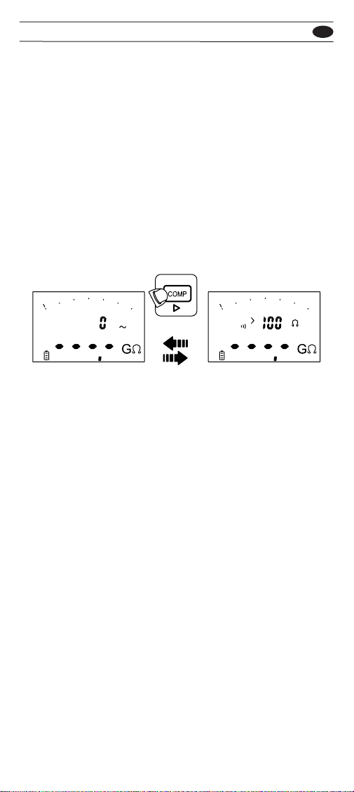
3. The meter displays the " >" symbol and the maximum
resistance for the range when measured resistance is
higher than the maximum display range.
100M100M
10M
1M
0
TEST
TEST
=
TEST 500V
INSULATION
COM
500V
100M
100G
10G
1G
100M
10M
1M
0
100G
10G
1G
M
V
V
G
V
1. Before starting the test :
The circuit under test must be completely de-energized.
If the voltage detected is above 30V, ">30V" will appear on
the display. In this condition, the test is inhibited.
2. Press the Function button to display insulation resistance or
Leakage current during the test or when the test stops.
3. Lock mode: Press the Lock button to enter the Lock Mode.
Then press TEST button >1sec to start the test. The test
Press & Hold >1Sec
INT500 EN
11
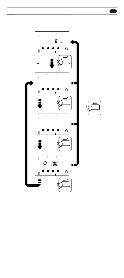
Before starting the Insulation Resistance test, select the
comparative value in Setup mode: 0.5MΩ, 10MΩ, 20MΩ,
50MΩ, 100MΩ, 200MΩ, 500MΩ, 1000MΩ.
Before starting the Earth-Bond Resistance test, select the
comparative value in Setup mode: 0.5Ω, 1Ω, 2Ω, 3Ω, 4Ω, 5Ω,
10Ω, 20Ω, 30Ω, 40Ω.
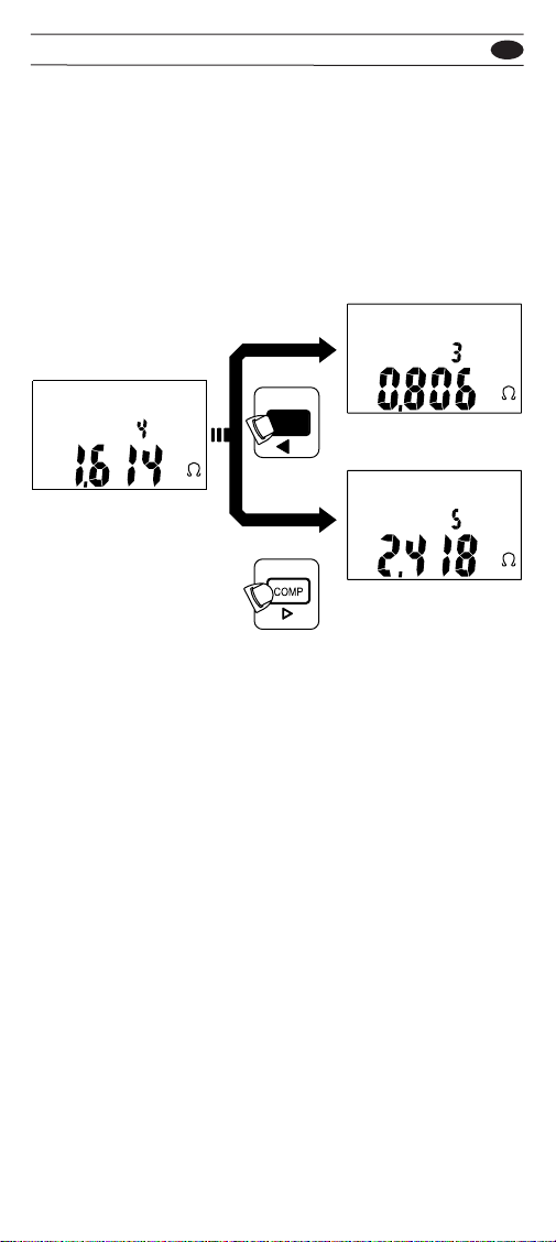
If the measured value is better than the selected compare
value, the Pass indicator will be green, otherwise it is red.
Using the Compare function
100M
100G
10G
1G
100M
10M
1M
0
100M
100G
10G
1G
100M
10M
1M
0
VM
COMPARE
Press
voltage will continue to be applied until the TEST/LOCK
button is pressed again.
4. Stop the output test voltage before removing the test leads
(to enable the tester to discharge capacitive circuits).
If the screen displays volts, wait until it reaches zero.
5. The meter displays the " >" symbol and the maximum
resistance for the range when measured resistance is
higher than the maximum display range.
INT500 EN
12
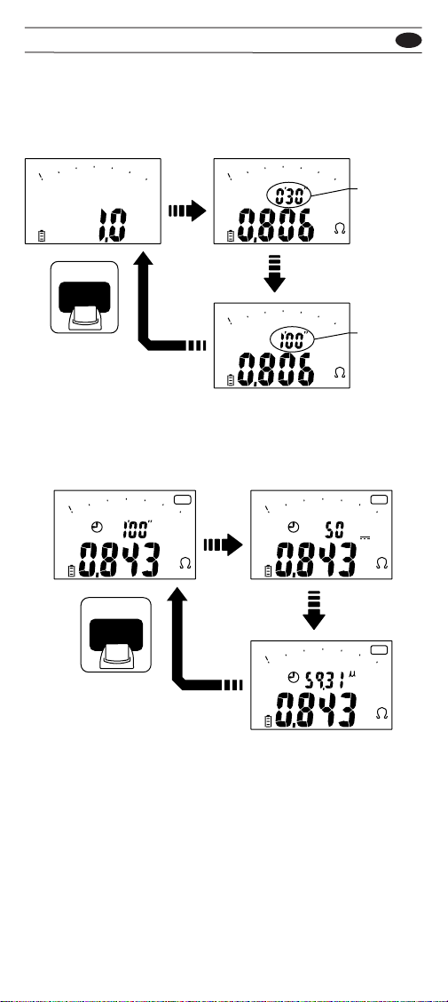
Measuring PI/DAR/Timer
Press TEST button to start/interrupt the PI/DAR test.
Press Function button during the PI/DAR test to switch display
the output voltage / leakage current / the time left of the test.
100M
100G
10G
1G
100M
10M
1M
0
G
V
Press>2Sec
Press
Press
Press
Press>2Sec LOCK
PI/DAR/t
100M
100G
10G
1G
100M
10M
1M
0
G
PI
100M
100G
10G
1G
100M
10M
1M
0
G
DAR
LOCK
PI/DAR/t
100M
100G
10G
1G
100M
10M
1M
0
G
LOCK
PI/DAR/t
LOCK
PI/DAR/t
LOCK
PI/DAR/t
PI(Polarization Index)=R10-min/R1-min
DAR(Dielectric Absorption Rations)=R1-min/(R30-sec or R15-sec)
Timer : Countdown timer
R10-min : the insulation resistance measured at the 10 minute
after pressing the TEST button.

INT500 EN
13
PI=R10-min/R1-min
Show the measured values after the PI test is
completed
100M
100G
10G
1G
100M
10M
1M
0
M
PI
100M
100G
10G
1G
100M
10M
1M
0
PI
Press
Press
Press
R1-min
R10-min
100M
100G
10G
1G
100M
10M
1M
0
M
PI
SETUP
R1-min : the insulation resistance measured at the 1 minute after
pressing the TEST button.
R30-sec : the insulation resistance measured at the 30 seconds
after pressing the TEST button.
R15-sec : the insulation resistance measured at the 15 second
after pressing the TEST button.
NOTE: R30-sec or R15-sec can be set in setup mode
NOTE: Countdown time interval can be set in setup mode
If the reading for DAR is bigger than 1.3 or PI is bigger than 2,
it indicate a good insulation quality.
When the measured resistance is higher than the maximum
range, the screen will display "Err" symbol for PI/DAR value.
INT500 EN
14
DAR=R1-min/R30-sec
Show the measured values after the DAR test
is completed
100M
100G
10G
1G
100M
10M
1M
0
100M
100G
10G
1G
100M
10M
1M
0
M
DARD AR
Press
Press
Press
R30-sec
R1-min
100M
100G
10G
1G
100M
10M
1M
0
M
DAR
SETUP
Show the measured values after the
countdown timer test is completed
100M
100G
10G
1G
100M
10M
1M
0
M
APO
Press
100M
100G
10G
1G
100M
10M
1M
0
M
APO
V
Press
Press
SETUP
100M
100G
10G
1G
100M
10M
1M
0
M
APO
A
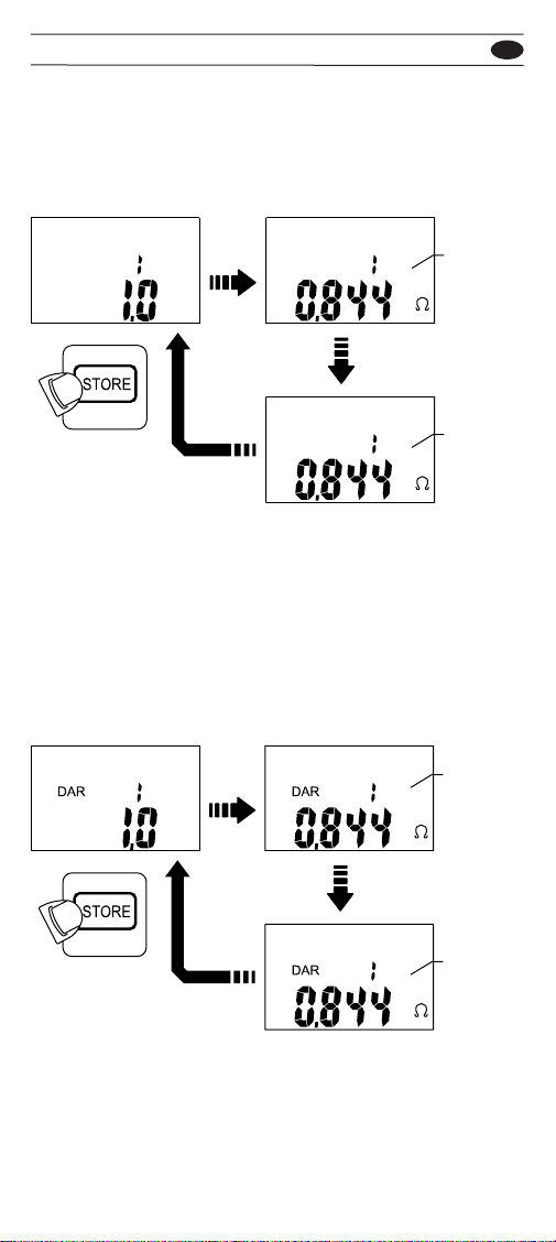
Store/Recall button :
1. Press Store/Recall button to store the test result. The screen
will show MEM symbol and the number of stored data when
the Store/Recall button is pressed.
2. In PI / DAR mode, Insulation, and Earth-bond resistance,
Store / Recall button is only available when the individual
Using the Store function

INT500 EN
15
Delete the last one recording set in the mode
Mode Recording Set
Insulation Output Voltage Leakage Current Insulation
Resistance
PI mode PI value R1-min R10-min
DAR mode DAR value R30-Sec or
R15-Sec R1-min
Earth-bond
Resistance Resistance
Voltage Voltage
Capacitance Capacitance
100M
100G
10G
1G
100M
10M
1M
0
G
V
5 Sec
Del Last
M
Press>5Sec
until the LCD shows dEL
MEM
MEM
test is completed.
3. Up to 1500 recordings / recording sets of each function
(Voltage, Continuity, Capacitance, Insulation, PI, DAR).
4. In Insulation, PI / DAR mode, the meter saves 3 dierent
readings at the same time (Recording Set).
INT500 EN
16
Search the stored value under RECALL mode
Press the Store/Recall button ≧2 sec to enter/exit the
RECALL mode.
If the memory is empty, the meter will display the “nOnE ”
symbol.
Using the Recall function
MEM
M
Press
MEM
M
SETUP
MEM
M
Press

INT500 EN
17
In RECALL mode, press STORE button can show the
insulation resistance, test voltage, and leakage current of the
selected reading set.
Read the stored value of insulation test under
RECALL mode
Insulation
Resistance
Current
Leakage
100M
100G
10G
1G
100M
10M
1M
0
M
V
APO
MEM
M
MEM
A
RECALL
Press
Press
Press
Press>2Sec
RECALL
MEM
V
DC
RECALL
Test
Voltage
Press>2Sec
RECALL
RECALL
INT500 EN
18
In RECALL mode, press STORE button can show insulation
resistance of the selected reading set.
In RECALL mode, press STORE button can show insulation
resistance of the selected reading set.
Read the stored value of PI test under RECALL
mode
Read the stored value of DAR test under
RECALL mode
MEM MEM
M
MEM
M
PI PI
PI
R1-min
R10-min
Press
Press
RECALL
Press
MEM MEM
M
MEM
M
R15-Sec
or
R30-Sec
R1-min
Press
Press
RECALL
Press

INT500 EN
19
Restore power by switching rotator or by pressing any button.
The backlight is automatically turned on at dark environment.
Press the following button while turning meter on from OFF
position.
Test button : display of the software version.
Store button : Reset all stored data
Lock button : Show the full display of the LCD
Function button : Enter Setup Mode
Auto Power O (Battery Saver)
Auto Backlight
Power-up options :
OFF
AC
V
APO
APO
V
LPF
OFF
30min
Table of contents
Other Power Probe Test Equipment manuals

Popular Test Equipment manuals by other brands


Simplex
Simplex Saturn 3000 DV Technical manual

ATC
ATC GTDHR FIRST Operating and maintenance instructions

Agilent Technologies
Agilent Technologies auroraSonata user guide

EUTECH INSTRUMENTS
EUTECH INSTRUMENTS PCSTestr35 quick guide

Emerson
Emerson Rosemount FS-HR-975 user manual

CRH
CRH CRL GLASS-CHECK PRO GC3001 operating manual


