Document Operating and Maintenance manual, AC100-CPT
Reference No. 162736
Revision A
Date 09-MAR-2021
Author AK
Power Prove www.powerprove.com
Leicester. LE5 5LZ. United Kingdom sales@powerprove.com
a division of Cressall Resistors Ltd. +44(0) 116 249 1722 Page 8 of 11
ii. Using external control and fan power
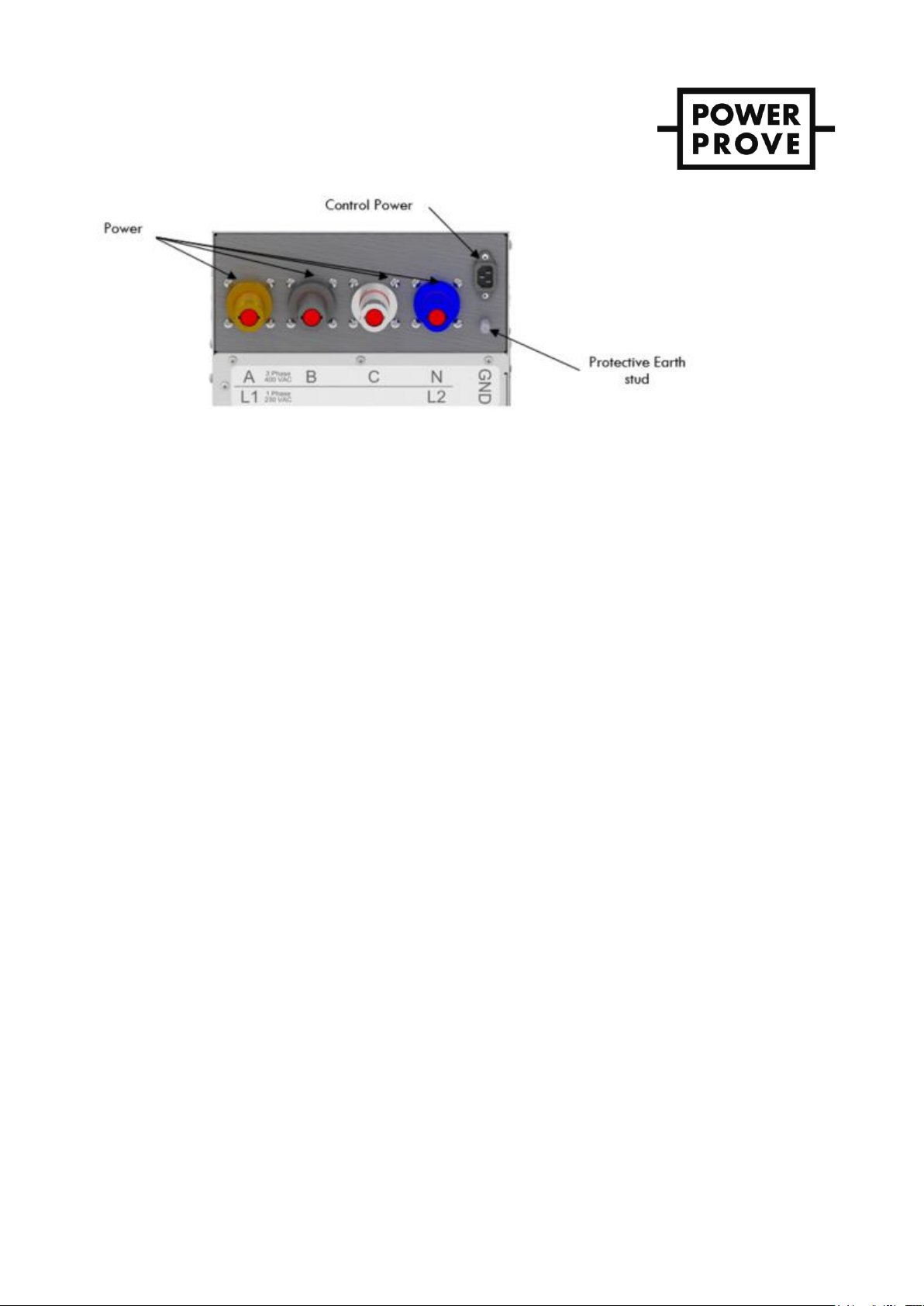
1. Connect the ground stud on the unit directly to a known earth-ground.
2. Connect all de-energized load power Powersafe to the unit Ensure cable size is sufficient to carry
the expected current. Failure to size conductors properly will lead to conductor overheating, which
will damage conductors and may pose a fire hazard.
3. Connect an external 3-pin 230VAC control cable to the 3-pin plug located on the connections
panel.
4. Set the “Control Source”switch to the “Ext” (External) position.
5. Energize the external power source with an acceptable voltage.
6. Energize the load power source with an acceptable voltage.
7. Turn the MAIN on/off power switch to the ON position with the voltage required. Your unit is
equipped with a voltage sensor that will not allow the unit operate if bus voltage exceeds
421VAC L-L (243VAC L-N). The blowers, meter, and green Main Power switch light will turn on
with an acceptable voltage level.
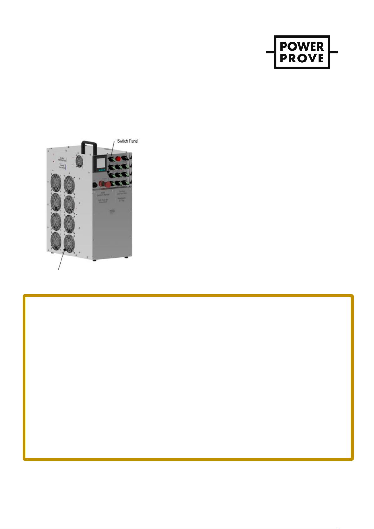
Caution! Make sure air is flowing from the exhaust port. Failure to have proper airflow will cause unit to
overheat and fail.
Applying & disconnecting load
1. Start with the Main Power switch located in the ON position, the Control Source switch in the correct
position, and the Master Load switch in the OFF position.
2. “Shock” Loading
a. Begin with the Master switch in the OFF position
b. Place the desired test step switches in the ON position.
c. Place the Master switch ON to engage all selected load simultaneously.
3. “Step” Loading
a. Begin with the Master switch in the ON position.
b. Place desired step switches in the ON position to apply load systematically.
4. Disconnect individual steps by placing the step switches in the OFF position and/or disconnect all load
simultaneously by placing the Master switch in the OFF position.
5. “Step” and “Shock” loading can be used in conjunction with one another during testing.
6. Repeat tests as needed.
Shutdown
1. Place all load step switches in the OFF position. Put Master Load in the OFF position.
2. Allow fans to operate at least five minutes or until exhaust, air is cool before shutting them off. This cooling
period will extend the life of your load bank.
3. Turn Main Power switch to the OFF Position.
4. Turn off Generator/Power source for the unit.
5. If using external power source remove the 230V control plug.
6. Before removing the main load cables, verify that the source power is off. Once this is verified, disconnect
the load cables from the Powersafe sockets.
7. Remove ground connections.
8. Move the unit to storage.