EkoStinger Fixed System User manual

Installation Manual | Fixed System
V 1.02
1/28/2021 EkoStinger|140 Despatch Dr, East Rochester, NY 14445|855.833.7940|info@ekostinger.com
Need help? Please call EkoStinger at 855-833-7940
www.ekostinger.com

Installation Manual | Fixed System
Important Safety Instructions
EkoStinger|140 Despatch Dr, East Rochester, NY 14445|855.833.7940|info@ekostinger.com pg. 1
General Safety Warning
WARNING! Read all safety warnings and all instructions. Failure to follow the warnings and instructions may
result in serious injury.
SAVE A WARNINGS AND INSTRUCTIONS FOR FUTURE REFERENCE
1) Work Area Safety
Keep work area clean and well lit. Cluttered or dark areas invite accidents.
Do not operate power tools in explosive atmospheres, such as in the presence of ammable liquids,
gases or dust. Power tools create sparks which may ignite the dust or fumes.
Keep non needed personnel away while performing the installation. Distractions can cause accidents.
2) Personal Safety
Use personal protective equipment. Always wear eye and ear protection.
3) Unit Servicing
Recheck declared Torque after the rst 1,000 miles.
Recheck declared Torque every 10,000 miles.
4) Manufacturer's suggested Torque values
3/8" Hardware: 23 ft-lb
1/4" Hardware: 6.3 ft-lb
U.S. Recommended Bolt Torque Table
Size
Recommended Torque
Grade 2 Grade 5 Grade 8 18-8 S/S Bronze Brass
Coarse Fine Coarse Fine Coarse Fine Coarse Fine Coarse Fine Coarse Fine
* #4 - - - - - - 5.2 - 4.8 - 4.3 -
* #6 - - - - - - 9.6 - 8.9 - 7.9 -
* #8 - - - - - - 19.8 - 18.4 - 16.2 -
*#10 - - - - - - 22.8 31.7 21.2 29.3 18.6 25.9
1/4 4 4.7 6.3 7.3 9 10 6.3 7.8 5.7 7.3 5.1 6.4
5/16 8 9 13 14 18 20 11 11.8 10.3 10.9 8.9 9.7
3/8 15 17 23 26 33 37 20 22 18 20 16 18
7/16 24 27 37 41 52 58 31 33 29 31 26 27
1/2 37 41 57 64 80 90 43 45 40 42 35 37
9/16 53 59 82 91 115 129 57 63 53 58 47 51
5/8 73 83 112 128 159 180 93 104 86 96 76 85
3/4 125 138 200 223 282 315 128 124 104 102 118 115
7/8 129 144 322 355 454 501 194 193 178 178 159 158
** 1 188 210 483 541 682 764 287 289 265 240 235 212
* Sizes from 4 to 10 are in in.-lbs.
Sizes from 1/4 up are in ft.-lbs.
**Fine thread gures are for 1-14.
Grade 2, 5, and 8 values are for plated bolts.

Installation Manual | Fixed System
Table Of Contents
EkoStinger|140 Despatch Dr, East Rochester, NY 14445|855.833.7940|info@ekostinger.com pg. 2
Important Safety Instructions
Table of Contents
Parts ist
Shipped Items
Hardware Box (Fixed)
Exploded Diagram - Part Numbers
Assembly
Know Your Stinger Parts
Assembly Tools
Front Brace Assembly
Rear Brace Assembly
Attaching Bottom Support Angle
Attaching Cables
Assembly Finished
Installation
Installation Tools
Airline Cover
Measuring and Prep
Raising Stinger
I-Beam Anchoring via Plates
Wing Gussets
Installation Complete
Notes
1
2
3
4
5
6
7
8-9
10-11
12
13
14
15
16-17
18-22
23-25
26-28
29
30
31
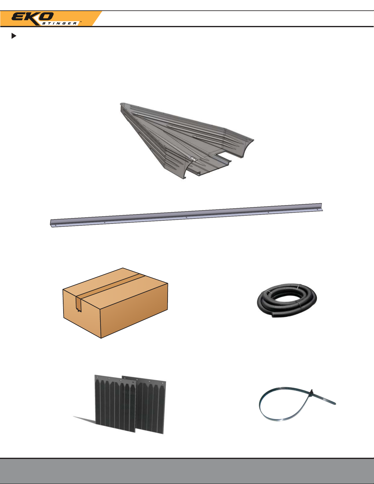
1x - Stinger Shell - M Dxxx-Fx
1x - Bottom Support Angle - 10093F
1x - Hardware Box (Fixed) - HBFX
2x - 24" x 27" Aerodynamic Mud Flaps 14x - Zip Ties
8’ - Wire oom
Installation Manual | Fixed System
Parts List - Shipped Items
What comes with your EkoStinger order?
EkoStinger|140 Despatch Dr, East Rochester, NY 14445|855.833.7940|info@ekostinger.com pg. 3

Installation Manual | Fixed System
Parts List - Shipped Items
What comes with your EkoStinger order?
EkoStinger|140 Despatch Dr, East Rochester, NY 14445|855.833.7940|info@ekostinger.com pg. 4
20004 161/4"-20x1" Washer Head w/Patch
Part # Items QTY
Fixed Plate Bolts w/Loctite Patch
FX1001B
20091
20010
16
16
3/8"-16x1.5" Hex Bolt SS
3/8"-16 Nylock Nut
Part # Items QTY
Fixed Faceplate Hardware Bag
FX1002B
20044
20085
20006
EYE-H
10
4
7
1
1/4"x1" SS Fender Washer
1/4"-20x1" SS Hex Bolt
1/4"-20 Nylock Nut
Eyehook 1/4"x1"x7/8"
Part # Items QTY
Fixed Support Hardware
FX1005B
20044
20085
20006
2
2
2
1/4"x1" SS Fender Washer
1/4"-20x1" SS Hex Bolt
1/4"-20 Nylock Nut
Part # Items QTY
Wing Gusset Hardware Bag
FXG S-HWB
FX-GUS
20018
20004
1
2
2
3" x 3" x 5" Aluminum Bracket
Small Plate
1/4"-20 Bolt
Part # Items QTY
Rear Wing Gusset - Flat Bottom
FX1004F
FXBR-
FXBR-R
2
2
6"x15"90°Plate 4 Holes, 4 Slots, Powder
Coated, Painted, eft (Steel Brace Plate)
6"x15"90°Plate 4 Holes, 4 Slots, Powder
Coated, Painted, Right (Steel Brace Plate)
Part # Items QTY
Fixed Braces
FXSP
FXFP
FX1002B
8
8
1
1/4"x4.25" Aluminum Plate (Mold Brace Spacer)
1/8"x4.25" Aluminum Plate (Fixed Faceplate)
Fixed Faceplate Hardware Bag
Part # Items QTY
Faceplates and Spacers with Bolts and Nuts
FX1002A
FX1001B
PF Bag
1
1
Fixed Plate Bolts w/ octite Patch
arge Plates - Fixed
Part # Items QTY
Fixed Large Plate Bag
FX1001A
FX-CB
FX1005B
2
1
Rear Support Cable
Fixed Support Hardware
Part # Items QTY
Rear Cable Bag with Fixed Support Hardware Bag
FX1005A
20017F
20017RED
4
4
arge Plate
arge Plate - Paint Red
Part # Items QTY
Large Plate Fixed nit Bag
LPF Bag
Hardware Box (Fixed) - HBFX
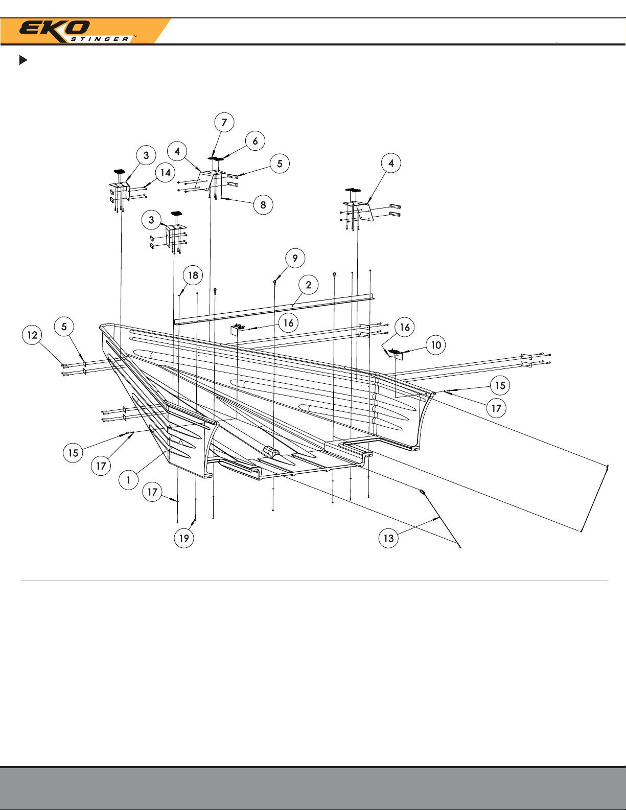
Installation Manual | Fixed System
Parts List - Exploded Diagram
EkoStinger|140 Despatch Dr, East Rochester, NY 14445|855.833.7940|info@ekostinger.com pg. 5
M Dxxx-Fx
10093
FxBR-
FxBR-R
FxFP
20017RED
20017
20004
EYE-H
FX-GUS
20091
FX-CB
20010
20085
20006
20044
20006
20085
1
2
3
4
5
6
7
8
9
10
12
13
14
15
16
17
18
19
Stinger Shell
Bottom Support Angle
FX eft Brace
FX Right Brace
FX Faceplate
Red Plate
Plate
Plate Bolts
Eyehook
Wing Gusset
FX Faceplate Bolt
Rear Support Cable
3/8"-16 ocknut
Wing Gusset Shell Bolt
Wing Gusset Shell Nylock
Washer
1/4"-20 ocknut
Bottom Support Angle Bolt
# #Part Name Part NamePart Number Part Number

Installation Manual | Fixed System
Assembly - Stinger Unit
EkoStinger|140 Despatch Dr, East Rochester, NY 14445|855.833.7940|info@ekostinger.com pg. 6
Know Your Stinger Parts - Assembled Stinger Unit
Right Brace
FxBR-R
eft Brace
FxBR-
eft Brace
FxBR-
Right Brace
FxBR-R
Plate
20017F
(4x)
Red Plate
20017F
(4x)
Support Cable Hole
(2x)
Stinger
Shell
M Dxxx-Fx
Wing Gusset
FX-GUS
Bottom Support Angle
10093F
Support Cables
FX-CB

9/16 Wrench
Installation Manual | Fixed System
Assembly - Stinger Unit - Required Tools
EkoStinger|140 Despatch Dr, East Rochester, NY 14445|855.833.7940|info@ekostinger.com pg. 7
Cordless Impact Driver
Socket Adapter
7/16 Wrench
7/16 Socket
9/16 Socket
3/8 Driver

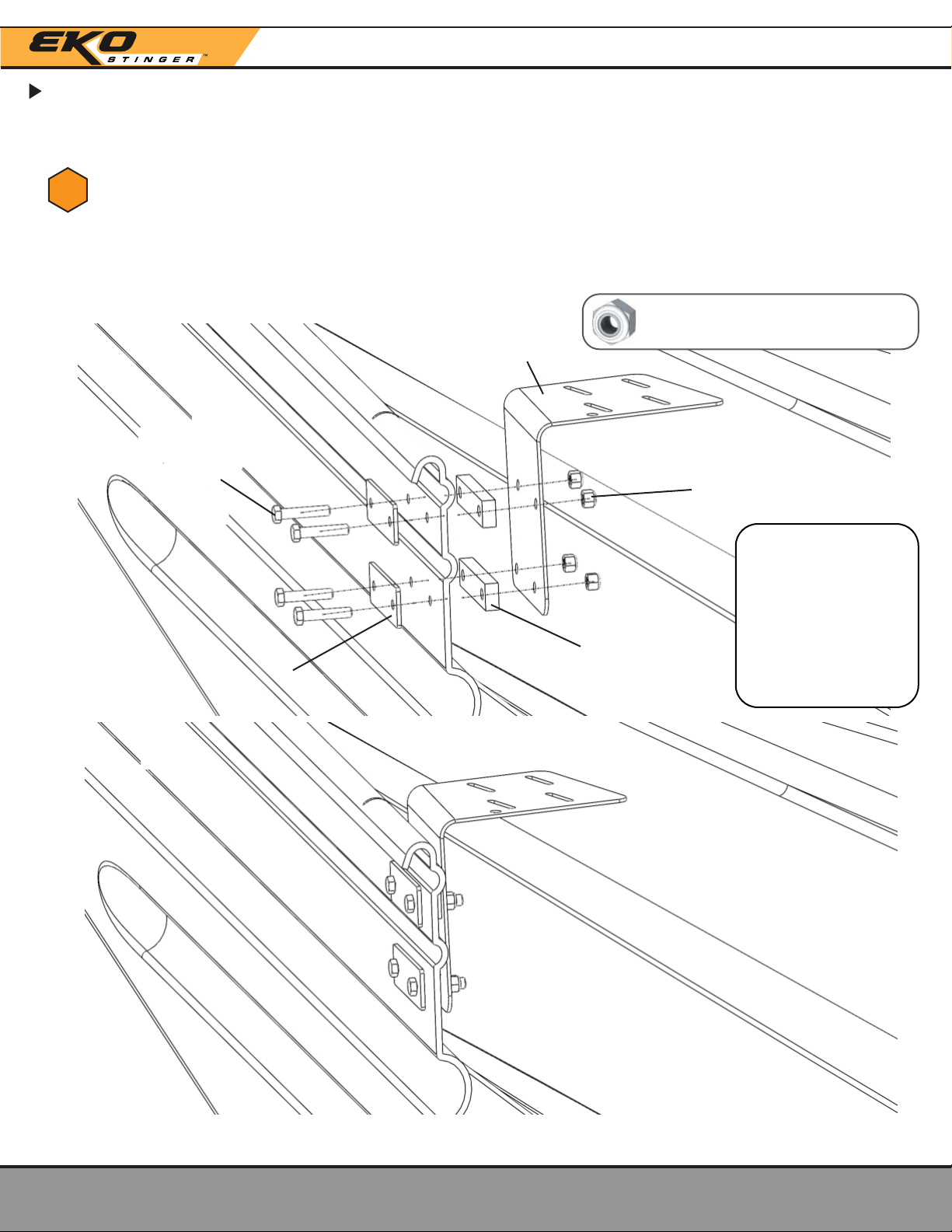
Installation Manual | Fixed System
Assembly - Stinger Unit
EkoStinger|140 Despatch Dr, East Rochester, NY 14445|855.833.7940|info@ekostinger.com pg. 8
Torque
23 ft-lb
Refer to
manufacturers
suggested
Torque values
on pg. 2.
Front Brace Assembly
Attach the Left Brace (FxBr-L) by inserting 4x Outside Bolts (20091)
through 2x Faceplates (FxFp), Stinger Shell, and continuing through the
2x Spacers (FxSp), the Left Brace (FxBr-L), and fastening at the end with
4x Lock Nuts (20010). Make sure the Brace is facing outward just like
in the picture. Do the same for the right side.
1
eft Brace
FxBr-
(Right Side: FxBr-R)
3/8 ock Nut
20010
(4x)
Spacer
FxSp
(2x)
Faceplate
FxFp
(2x)
Outside Bolt
3/8-16 x 1.5 Hex Bolt
20091
(4x)
Fixed Faceplate Hardware Bag
Faceplates and Spacers w/ Bolts + Nuts

Installation Manual | Fixed System
Assembly - Stinger Unit
EkoStinger|140 Despatch Dr, East Rochester, NY 14445|855.833.7940|info@ekostinger.com pg. 9
Fixed Plate Bolts w/Loctite Patch
Fixed Large Plate Bag
Front Brace Assembly
Attach the Plate (20017F) by inserting 2x Plate Bolts (20004) through
the Brace and into the threaded Plate. Make sure the Plate
is facing toward the center of the Brace, just like in the picture.
Do the same on the other side. Finger tighten for now.
2
Plate
20017F
Plate Bolt
20004
(2x)
Installation Manual | Fixed System
Assembly - Stinger Unit
EkoStinger|140 Despatch Dr, East Rochester, NY 14445|855.833.7940|info@ekostinger.com pg. 10
Torque
23 ft-lb
Refer to
manufacturers
suggested
Torque values
on pg. 2.
Rear Brace Assembly
Attach the Left Brace (FxBr-L) by inserting 4x Outside Bolts (20091)
through 2x Faceplates (FxFp), Stinger Shell, and continuing through the
2x Spacers (FxSp), the Left Brace (FxBr-L), and fastening at the end with
4x Lock Nuts (20010). Make sure the Brace is facing inward just like in
the picture. Do the same for the right side.
3
eft Brace
FxBr-
3/8 ock Nut
20010
(4x)
Spacer
FxSp
(2x)
Faceplate
FxFp
(2x)
Outside Bolt
3/8-16 x 1.5 Hex Bolt
20091
(4x)
Fixed Faceplate Hardware Bag
Faceplates and Spacers w/ Bolts + Nuts

Installation Manual | Fixed System
Assembly - Stinger Unit
EkoStinger|140 Despatch Dr, East Rochester, NY 14445|855.833.7940|info@ekostinger.com pg. 11
Plate
20017
Plate Bolt
20004
(2x)
Fixed Plate Bolts w/Loctite Patch
Fixed Large Plate Bag
Rear Brace Assembly
4Attach the Plate (20017) by inserting 2x Plate Bolts (20004) through
the Brace and into the threaded Plate. Make sure the Plate
is facing toward the center of the Brace, just like in the picture.
Do the same on the other side. Finger tighten for now.

Torque
6.3 ft-lb
Refer to
manufacturers
suggested
Torque values
on pg. 2.
Installation Manual | Fixed System
Assembly - Stinger Unit
EkoStinger|140 Despatch Dr, East Rochester, NY 14445|855.833.7940|info@ekostinger.com pg. 12
5
Attaching Bottom Support Angle5
Fixed Support Hardware Bag
Attach the Bottom Support Angle (10093F) by installing 3x Eyehooks (EYE-H)
from the top and 4x Hex bolts (20085) from the bottom. Secure each
Eyehook and Hex bolt using a washer (20044) and a Locknut (20006).
Eyehook
EYE-H
(3x)
Cable
FX-CB
(2x)
No Cable
ocknut
20006
(7x)
Note: Two of the Eye Hooks come with cables pre-
attached. These need to be installed on the sides.
The center EyeHook is not attached to a cable.
Washer
20044
(7x) Hex bolt
20085
(4x)

Installation Manual | Fixed System
Assembly - Stinger Unit
EkoStinger|140 Despatch Dr, East Rochester, NY 14445|855.833.7940|info@ekostinger.com pg. 13
Attaching Cables
6
Rear Cable w/ Fixed Support Hardware
Attach the cross cables using the provided carabiners to the rear Braces.

Installation Manual | Fixed System
Assembly - Stinger Unit
EkoStinger|140 Despatch Dr, East Rochester, NY 14445|855.833.7940|info@ekostinger.com pg. 14
Assembly Finished
7Your Fixed System Stinger assembly is now nished. Please look over all bolts,
and make sure they are tightened to their specied Torque values (reference
pg.2 ).

Installation Manual | Fixed System
Installation
EkoStinger|140 Despatch Dr, East Rochester, NY 14445|855.833.7940|info@ekostinger.com
Installation - Required Tools
Installing the Stinger Unit onto the Trailer
Cordless
Impact
Driver
3/8 Driver
Tape Measure
pg. 15
OPTIONAL LIFT KIT
An optional lift kit can be provided containing ocking Block and Tackle and Nose Cable, which would
allow the system installation to be performed by one installer, but we recommend two installers for ease
of installation.
Without the ift Kit, we recommend the installation to be performed by at least 3 installers.

Installation - Airline Cover
EkoStinger|140 Despatch Dr, East Rochester, NY 14445|855.833.7940|info@ekostinger.com
Installation Manual | Fixed System
pg. 16
Locate the Wire Looms (8x) and the Zip Ties (14x).
Starting with the front air line and electrical wires, slip the protective wrap
over the air lines and wires. Position the cover so there is no more than
four (4) inches of exposed lines. Secure with Zip Ties.
8
9
4”MAX

Installation - Airline Cover
EkoStinger|140 Despatch Dr, East Rochester, NY 14445|855.833.7940|info@ekostinger.com
Installation Manual | Fixed System
Continue working the Wire Looms over the air lines and electrical harness
until the rst cable restraint and spring tensioner is reached. Secure with
Zip Ties every 12 inches.
Continue installing the Wire Loom until the entire air line, and electrical
wiring is covered from end to end. Secure with Zip Ties every 12 inches.
10
11
pg. 17

Installation Manual | Fixed System
Installation - Stinger Unit
EkoStinger|140 Despatch Dr, East Rochester, NY 14445|855.833.7940|info@ekostinger.com pg. 18
Measuring and Prep
Locate the starting I-Beam, determined by the customer’s Suspension
Sub-Frame placement.
12
Starting position will be a minimum of 42” and a maximum of 48” from
the leading edge of the tire from customer's designated maximum
forward position.
42”-48”
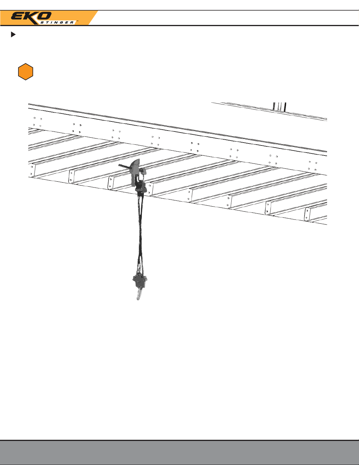
Installation Manual | Fixed System
Installation - Stinger Unit
EkoStinger|140 Despatch Dr, East Rochester, NY 14445|855.833.7940|info@ekostinger.com pg. 19
Measuring and Prep
Mark center of the I-Beam and hang Winch with a Quick Clamp.
13
Table of contents
Popular Industrial Equipment manuals by other brands


Greenlee
Greenlee Gator Intelli-PUNCH instruction manual

Siemens
Siemens SINUMERIK MPP 1500D Equipment manual

schmersal
schmersal AZM300B-I2-ST-SD2P-A-T-DU Operation instructions

Titan
Titan VS-32-L Operating and maintenance instructions

Siemens
Siemens SIMATIC NET SCALANCE M-800 Getting started

Premier
Premier 470 Installation, Inspection, Operation & Maintenance Guide

TigerStop
TigerStop TigerSPC user manual

Absolute Process Instruments
Absolute Process Instruments API 1400 G quick start guide

Goudsmit
Goudsmit Easy Clean Cleanflow SECE Series user manual

GRUNDFOS ALLDOS
GRUNDFOS ALLDOS Oxiperm C 164 Series Operation and service manual

Viking-Cives
Viking-Cives 500HD manual

CKD
CKD M4G Series instruction manual