Power Step Komatsu 960E User manual

PSA-K960E-FS 23-1-15
Model No.: PSA-K960E-FS
Serial No.:960E-001 ~
Date Manufactured: October 2009
FOLDING STAIRWAY
Manual for Komatsu 960E Truck

FOLDING STAIRWAY
Komatsu 960E Truck
Pg2
PSA-K960E-FS 23-1-15
CONTENTS
Page 3Section 1 Mounting and Installation
7Section 2 Electrical Installation
8Section 3 Operating Procedure
Mechanical & Hydraulic Adjustment procedure
13 Section 4 Recommended Maintenance Procedure
14 Section 5 Assembly Complete-Main Assemblies
15 5-1 Assembly Complete
Parts List
16 5-2 Landing Assembly
Parts List
18 5-3 Stair Assembly
Parts List
20 5-4 Hydraulics -Cylinder Assembly
Cylinder and Components
Control box Assembly
Valve Diagram
25 5-5 Electrical Cabinet Assy
Parts List
26 5-6 Electrical System
Wiring Diagrams
Harnesses
31 Hydraulic Valve Kit
32 Mounting Plates

FOLDING STAIRWAY
Komatsu 960E Truck
Section 1. Mounting and Installation
See Page 4
Pg3
PSA-K960E-FS 23-1-15
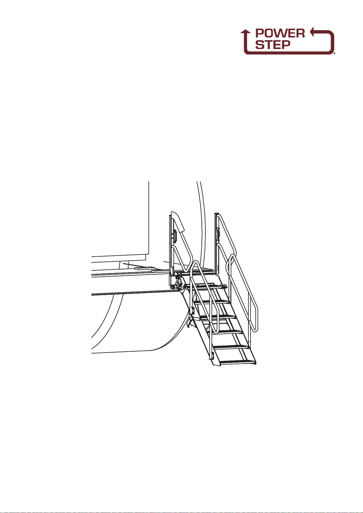
PROCEDURE (Drawings 23635 & 23636)
See Drawing 23635 (Adjustments)
1. Set up the stair set with bolting faces of the landing vertical,like it will be when
installed on the truck.
2. With one of the cylinder pins removed, lower the stair to its' deployed position as
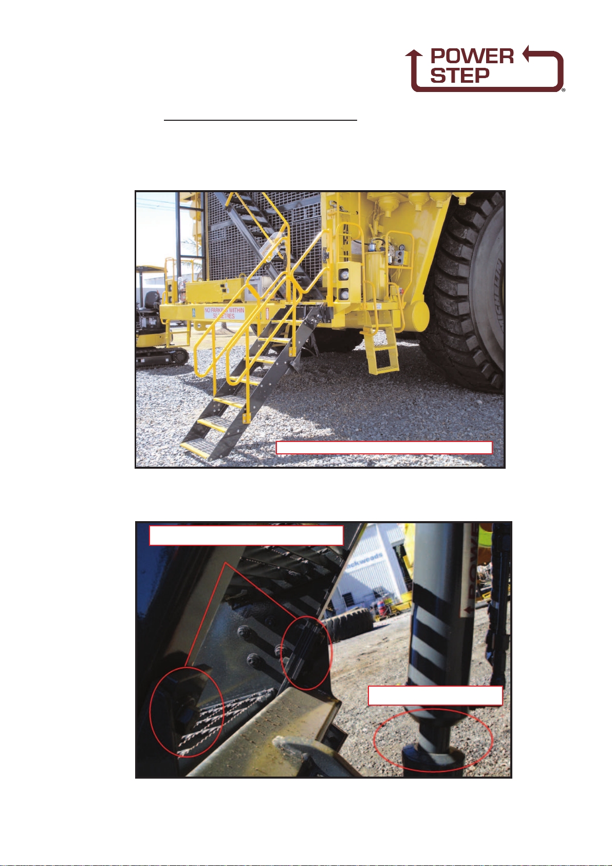
seen in View 2. Adjust the angle of inclination of the stair to 44 - 45Deg. to the
horizontal. Adjust by grinding the stop pads on both stiles or by building the stop
pads up with weld and then grinding. The bearing faces should be smooth and
flat so as not to bite into the flange plate quickly, thereby losingthe adjustment.
(This procedure should be repeated periodically during the service life of the stair
set.) Views 2 & 3.
3. Replace the cylinder pin and fully retract the cylinder. Ensure that the retracted
cylinder allows the stair to decline to the angle set in ii above. If not, adjust the
position of 23 675 Stair Actuator Attachment on the stair stile. View 2.
4. By extending the cylinder, raise the stair to the vertical stowed position. View 1.
5. Adjust the position of the Stair Buffer Bracket 23 653 on the stair stile so that the
buffer is compressed firmly when the stair is in the stowed position. View 1.
6. Adjust the positions of the Handrail Bumpers 23 651 mounted to the stair stiles and
handrail posts so they bear firmly on the handrails when the stair is stowed. These
bumpers are there to prevent vibration and rattling. View 1.
7. Adjust the position of the Go Switch Trigger 23 657 so the Go Switch creates the
appropriate connection when the stair is raised, View 4.
See Drawing 23636 (Bolting Pads)
1. Per Views 1, 2 & 3, attach the Bolting Pads to the bolt-on bumper extension at the
end of the central fixed bumper. Weld only to the extension.
2. Per View 4, fit the assembled stair set to the bolting pads, without the Landing
Deck or Landing Floor Infill fitted.
3. Per Views 5 and 6, fit the Landing Floor Infill and then the Landing Deck.
NOTE
Follow all on-site/Mine lifting and safety procedures when installing
PSFS to Truck.

FOLDING STAIRWAY
Komatsu 960E Truck
Section 1. Mounting and Installation 23635
Pg4
PSA-K960E-FS 23-1-15
P30-006

FOLDING STAIRWAY
Komatsu 960E Truck
Section 1. Mounting and Installation 23636
Pg5
PSA-K960E-FS 23-1-15
VIEW 1
VIEW 6
VIEW 3
VIEW 4
VIEW 5
VIEW 2

FOLDING STAIRWAY
Komatsu 960E Truck
Section 1. Mounting and Installation (Dimensions) 23678
Pg6
PSA-K960E-FS 23-1-15

FOLDING STAIRWAY
Komatsu 960E Truck
Section 2. Electrical Installation
Pg7
PSA-K960E-FS 23-1-15
Procedure
Remove centre console panel in cabin -
- to do this remove six (6) screws and gear selection knob.
Position stairway indicator panel on centre console, above hour meter.
- drill two mounting screw holes (6mm or 7/32")
- one electrical cable hole (12mm or 15/32")
- do not re-fix console Panel
Remove four (4) screws holding Komatsu fuse panel behind operator's seat. Drill one hole
to insert Caterpillar fuse holder - fit fuse holder, into fuse indicator panel - tighten. Drill
size (12mm or 15/32").
Remove rear access panel from back of cabin and run short conduit through the main
cable gland to inside centre console, ensuring conduit goes underneath control box.
Connect blue wire start from conduit above to blue wire of cabin indicator panel harness.
In rear access, connect black wire, with 10mm eye terminal to machine ground, and blue
wire to outer terminal of newly inserted fuse holder.
Install short blue wire to screw terminal of Komatsu circuit breaker, and other end to fuse
holder.
Run wiring harness from Power Step Folding Stairway magnetic proximity switch around
under radiator, and follow cabling/hose routing up to air line/ electrical outlet on rear Right
Hand Side of cabin.
Drill hole in RH Cabin access panel - route wiring harness in through access panel, and
through to under centre console - connect wires appropriately as colour coded. Hole
saw/drill size (24mm), cable tie harness as appropriate, approximately every 300mm.

FOLDING STAIRWAY
Komatsu 960E Truck
Section 3. Operating Procedure
Pg8
PSA-K960E-FS 23-1-15
To Lower Stair
· Position truck in a leveled, safe area (whenever possible).
· Ensure that the area below is clear of obstacles and people.
· Apply the park brake.
· Once park brake is applied, the stair will deploy.
· If the truck is parked in uneven ground, the bottom of the stair may touch the
ground before the stair is in a fully lowered position; should this occur, descend the
stair with caution.
To Raise the Stair
· Ascend the stair.
· Ensure area around the stair is clear of people.
· Release the park brake; and the stair will rise and stow into a vertical position.
· Note that the stair does have a pressure valve that senses if someone is standing
on the stair at time of rising; and it will automatically stop; or would not rise at all.

FOLDING STAIRWAY
Komatsu 960E Truck
Section 3. Operating Procedure - Notes
Mechanical Adjustment
Pg9
PSA-K960E-FS 23-1-15
ENSURE THE STEP IS IN THE LOWER POSITION
1. PUT STEP IN THE LOWERED POSITION & LOOSEN 8
BOLTS HOLDING THE CYLINDER BEAM
2. ENSURE THE CYLINDER IS IN THE
RETRACTED POSITION

FOLDING STAIRWAY
Komatsu 960E Truck
Section 3. Operating Procedure- Notes
Mechanical Adjustment
Pg10
PSA-K960E-FS 23-1-15
Hydraulic Adjustment
1. OPEN LID
2. REMOVE SIDE COVER
(HELD ON BY 4 SCREWS)
3. INSERT GAUGE INTO
THE LIFT SIDE OF THE
CYLINDER
(MIN 5000PSI RATED GAUGE)
3. RE TIGHTEN 8 BOLTS
AND RAISE THE STAIR
UNTIL THE CYLINDER IS
FULLYEXTENDED
4. ADJUST THE BUFFER TO
GET SOME CRUSH WHEN
IN THE RAISED POSITION
6. LOOSEN BRACKETS AND
ADJUST AS REQUIRED
5. MAKE SURE THE
“GO SWITCH” STRIKER
IS ABOUT 5MM FROM
THE SWITCH

FOLDING STAIRWAY
Komatsu 960E Truck
Section 3. Operating Procedure- Notes
Hydraulic Adjustment
Pg11
PSA-K960E-FS 23-1-15
AS AFINAL SETTING PLACE A40KG WEIGHT ON THE BOTTOM
STEP. IF NEEDED ADJUST THE PRESSURE SO THE STEP DOES NOT
RAISE WITH THE WEIGHT ON BUT DOES LIFT WHEN IT IS NOT ON.
TURN THE ADJUSTING SCREW IN OR OUT USING A6mm ALLEN KEY SETTING THE
PRESSURE TO 1725 PSI. (+/- 25PSI.) WHEN RAISING THE STAIR
(THIS PRESSURE IS AGUIDE BEFORE FINAL ADJUSTMENT)
RELEASE LOCK NUT(27MM)
REMOVE BLACK CAP

1. Lower the stair.
2. Remove the Cylinder with hoses attached.
3. Turn the Cylinder over so the Hydraulic hoses are on top of the cylinder.
This is also puts any air in the Cylinder on top.
4. Ensure Power Pack Hydraulic oil reservoir is full of oil.
5. Hold the Cylinder level, hoses and Lock Valve on top, and cycle(operate) cylinder
several times.
6. Finally when retracting the rod,hold the “Cylinder end” higher and than the “Rod
end” and close the Cylinder.
7. Then hold the Cylinder so the “Rod end” is higher and fully extend the Cylinder.
8. Repeat Step (6) above.
9. All air should now be out of cylinder.
10. Turn cylinder over and refit to the stair.
11. Ensure the Power Pack tank is full of oil. There should be no more problems.
NOTE:
If a problem persists, it may be required to remove the Cylinder hard plumbing and bleed
the Cylinder first. Also join the hoses from the PowerPack together and cycle them to
ensure there is no air.
Pg12
PSA-K960E-FS 23-1-15
FOLDING STAIRWAY
Komatsu 960E Truck
Section 3. Operating Procedure- Notes
To Bleed a Cylinder
ANY AIR IN THE CYLINDER WILL MOVE TO THE TOP WHEN HELD WITH THE
FITTINGS FACING UPWARDS
FACING UP FACING UP
AIR

FOLDING STAIRWAY
Komatsu 960E Truck
Section 4. Recommended Maintenance Procedure
Daily Visually check stairway and structure for damage, loose components,
handrails, etc.
Check for any back and forth motion when the Stair is stowed.
Adjustments may be required.
Check for hydraulic oil leaks from Hydraulic Cylinders, Plumbing and Hoses.
Notify the appropriate supervisor for any observed damage or malfunction.
* See attached Mechanical and Hydraulic adjustment & Cylinder bleeding
procedures if required.
500 Hours
- Grease on regular service.
- Check daily service as above.
- Check the Cylinder Clevis’s & Pins etc. for wear.
- Check all Rubber Buffers for damage or wear (Replace where required)
- Re-adjust all Mechanical & Hydraulic parts as per the “Mechanical & Hydraulic
adjustment procedure”
NOTE:If the Cylinder has been removed or the Emergency Valve used, the Cylinder will
require bleeding as per the “Cylinder bleeding procedure” (Pg 12)
Pg13
PSA-K960E-FS 23-1-15

FOLDING STAIRWAY
Komatsu 960E Truck
Section 5. Assembly Complete - Main Assemblies
See Pg 15
Pg14
PSA-K960E-FS 23-1-15
Item Part No. Part Name Qty
1
2
PSA-K960E-FS
PS-23667-A
ASSEMBLYCOMPLETE
LANDING ASSEMBLY
(INC.HANDRAILS)
REFER TO 5-1 FOR DETAILS
1
1
3PS-23662-A FOLDING STAIRS ASSEMBLY
(INC.HANDRAILS)
REFER TO 5-1 FOR DETAILS
1
4PS-62999-AH HYDRAULIC CYLINDER 1
5PS-960E-PBVC ELECTRICAL CABINET ASSEMBLY1

FOLDING STAIRWAY
Komatsu 960E Truck
Hydraulic Operation
Section 5-1 Assembly Complete PSA-K960E-FS
Pg15
PSA-K960E-FS 23-1-15

FOLDING STAIRWAY
Komatsu 960E Truck
Section 5-2 Landing Assembly PS 23667-A
Pg16
PSA-K960E-FS 23-1-15
Hydraulic Cylinder
See page 16

FOLDING STAIRWAY
Komatsu 960E Truck
Section 5-2 Landing Assembly PS-23667-A
Parts List
See Drawing Pg 16
Pg17
PSA-K960E-FS 23-1-15
Item Part No. Part Name Qty
1
2
3
4
5
6
7
8
9
10
11
12
13
14
15
16
17
18
19
20
21
22
23
24
25
26
27
28
29
30
31
32
33
PS-23667
PS-23671
PS-23673
PS-23669
PS-23651-01
PS-23668B
PS-75430
PS-63009-B
PS-23654-01
PS-23654-03
PS-23679
PS-23651-02
PS-61006-2
CPS-M16X40ZP
CPS-M16X40ZP
CPS-M16X30ZP
CPS-M10X35ZP
CPS-M10X30ZP
CPS-M10X16ZP
CPS-M8X16ZP
CPS-M6X50ZP
CPS-M6X20ZP
CPS-M5X50ZP
CPS-M10NN
CPS-M6NN
CPS-M5NN
CPS-M16WH
CPS-M10WH
CPS-M8WH
CPS-M5WH
PS-75430-B-930
CPS-M5X20ZP
PS-22655-02
LANDING FRAME
LANDING DECK-STEP TREAD
HAND SHIELD
LANDING FLOOR INFILL
HANDRAIL BUMPER
BOLTING PADS-MAIN MOUNTING BLOCKS
GO- SWITCH
BUSH
STAIR HINGE PIN
WASHER-(Dia 55)
SPECIAL WASHER
HANDRAIL BUMPER LINER
GREASE NIPPLE-M6 Str.
BOLT-M16 X 40 Bolt
BOLT-M16 X 40 Socket head
BOLT-M16 x 30 (For infill)
BOLT-M10 x 35
BOLT-M10 x 30
BOLT-M10 x 16
BOLT-M8 x 16
BOLT- M6 x 50 Socket head
BOLT-M6 x 20 Pan Head
BOLT - (Go Switch)
NUT-NYLOC-M10
NUT-NYLOC-M6
NUT-NYLOC-M5
WASHER - HARDENED - M16
WASHER - HARDENED - M10
WASHER - HARDENED - M8
FLAT WASHER- M5
GO SWITCH BRACKET
BOLT-M5 x 20
BUSH-(NYLON)
1
1
1
1
2
2
2
2
2
2
8
2
2
6
2
2
6
4
4
4
2
6
4
6
8
4
2
20
4
8
2
4
2

FOLDING STAIRWAY
Komatsu 960E Truck
Section 5-3 Stair Assembly PS-23662-A
Pg18
PSA-K960E-FS 23-1-15

FOLDING STAIRWAY
Komatsu 960E Truck
Section 5-3 Stair Assembly PS23662-A
Parts List
See Drawing Page 18
Pg19
PSA-K960E-FS 23-1-15
Item Part No. Part Name Qty
1
1A
2
2A
3
4
5
6
7
8
9
10
11
12
13
14
15
16
17
18
19
20
21
22
23
PS-23662 LH
PS-23662 RH
PS-23465 LH
PS-23465 RH
PS-22266A
PS-23659
PS-23672-99
PS-23672-98
PS-P30-006
PS23651-01
PS-23651-02
PS-23656 LH/RH
PS-23653 LH/RH
PS-75430-T-90
PS-40002
CPS-M12X35ZP
CPS-M12X30ZP
CPS-M10X25ZP
CPS-M6X20ZP
CPS-M12NZP
CPS-M10NZP
CPS-M6NZP
CPS-M12WH
CPS-M10WH
PS-23639
STAIR STILES FABRICATION-LH
STAIR STILES FABRICATION-RH
STAIR EXTENSION-LH
STAIR EXTENSION-RH
STAIR TREADS
STAIR TREAD (Modified)
HANDRAIL-FRONT-INNER
HANDRAIL-REAR-OUTER
STAIR ACTUATOR ATTACHMENT
HANDRAIL BUMPER (Matched Pair)
HANDRAIL BUMPER LINER
HANDRAIL BUMPER MOUNTING(pair)
STAIR BUFFER BRACKET (Matched Pair)
GO SWITCH TRIGGER
RUBBER STOP
BOLT-M12 x 35
BOLT-M12 x 30
BOLT-M10 x 25
BOLT-M6 x 20 Pan Head
NUT-M12
NUT-M10
NUT-M6
WASHER-HARDENED-M12
WASHER-HARDENED-M10
BOLT ON JACKING BOLT KIT (Incl. bolts)
1
1
1
1
6
1
1
1
1
2
2
2
2
2
2
12
54
8
6
66
8
8
132
16
1 Kit

FOLDING STAIRWAY
Komatsu 960E Truck
Section 5-4 Hydraulics -Cylinder Assembly P/No. PS-62999-AH-960E
Pg20
PSA-K960E-FS 23-1-15
Item Part No. Part Name Qty
1
1A
1B
1C
1S
2
3
4
5
6
7
8
9
10
11
12
13
PS-62999-AH-960E
PS-62999-HPK
PS-62999-A
PS-62999-P
PS-63009-P
PS-63103
PS-63201
PS-61159
PS-61154
PS-61157
PS-61158-1MM
PS61163
PS-61160
PS-61147
PS-61158-1MM
PS-61145
PS-61183
-
HYDRAULIC CYL. (with hard plumbing )
HARD PLUMBING KIT
HYDRAULIC CYLINDER 2 1/2”
PIN - CYLINDER & RETAINING CLIPS
PIN - LUBRICATED (Incl.Nipple & Splt Pin)
SEAL KIT (Not shown)
VALVE - PILOT OPERATED LOCKING
FITTING - ELBOW-9/16” JIC
FITTING - ELBOW- O RING 1/4BSPPx9/16”JIC
FITTING - O RING 1/4BSPPx 9/16”JIC
FITTING - 1 mm RESTRICTION 90 DEG
REDUCER JIC x BSPP
TUBE (Cut to suit) 110mm
FERRULES
FITTING - 1mm RESTRICTION 90 DEG
FITTING- 9/6”JIC SWIVEL
TEE FITTING
HYD.HOSES (Supplied by Komatsu Aust.)
1
1
1
1
1
1
1
1
1
2
1
2
1
2
1
1
2
2
CYL. END
ROD END
NOTE: HYDRAULIC CYLINDER ASSEMBLYP/No PS- 62999-AH-960E includes Part No.s 1 to 12
Other manuals for Komatsu 960E
1
Table of contents
Other Power Step Truck manuals