PowerBox Systems iGyro SRS User manual

Instruction Manual
07/2015
®

-02-
Dear customer,
We are delighted that you have decided to purchase the PowerBox iGyro
SRS from our range.
We hope you have many hours of pleasure and success with this new type
of gyro system.
1. Product description
The PowerBox iGyro SRS is a special gyro system intended for
fixed-wing model aircraft. At the development stage our constant aim was
to combine maximum versatility with simplicity of operation. The system
incorporates a regulatory algorithm specifically developed for fixed-wing
models, which causes hardly any alteration in the model’s familiar flying
characteristics; at the same time the aeroplane flies much more smoothly
and accurately, and is less sensitive to unwanted weather-induced or
aerodynamic influences. The need for mixers, such as elevator to rudder
or flaps, is eliminated entirely. The iGyro exploits the latest servo bus
technology to minimise the extremely complex wiring arrangements
necessitated by previous gyro systems. The ability to assign any channel
to the gain adjusters makes it possible to set up the desired gyro effect
accurately in just one short flight. Independent adjustment of each of the
five outputs is possible, enabling the modeller to set up gyro gain and
direction of effect precisely. The separate GPS II sensor provides a
means of obtaining a constant gyro effect over the model’s full speed
range, effectively eliminating the problem of over-compensation leading to
oscillation in high-speed flight. A menu-based setup assistant makes it
possible to complete all the settings in just a few minutes.
Features:
- Extremely accurate triple-axis MEMS sensor
- Special regulatory algorithm designed for fixed-wing model aircraft
- Menu-based setup assistant
- Three-stage flight phase switching
- Three axes distributed to five servos, each adjustable independently
- GPS-regulated gyro gain
- Integral delta mixer
- Can be installed in any attitude
- Graphic OLED screen with 128x64 pixels
- Ultra-simple menu-controlled programming method using the Sensor-
Switch

-03-
- SRS technology for use with various bus systems:
Futaba S-Bus, Spektrum SRXL, Spektrum DSM2 / DSMX, JR DMSS,
HoTT, M-Link and Jeti
- Unrestricted channel assignment
- Digital output can be passed on to an SRS PowerBox system
- 16-bit processor for fast, high-resolution signal processing
- Settings can be stored on a PC and reloaded at any time
- Can be updated using the PowerBox USB Interface Adapter
- Robust aluminium case
2. Layout and connections
3. Fundamental factors for the understanding of the iGyro
3.1. Special characteristics of the regulatory algorithm:
The PowerBox iGyro SRS operates on all three axes, i.e. aileron,
elevator and rudder. The gyro has two different working modes:
- Heading mode: this mode is active when the transmitter stick is at the
centre position of the corresponding control surface. In this centre range
the iGyro maintains the last attitude defined by the operator at the
transmitter. A concrete example would be elevator control in knife-edge
flight: the iGyro eliminates the need to apply down-elevator to correct the
influence of the model’s Centre of Gravity, i.e. no elevator control
commands are required.
- Normal or damping mode: this mode is active when the transmitter
stick is moved away from the centre position of the corresponding control
surface. In this mode the iGyro simply has the effect of damping external
Aileron A
Aileron B
Elevator A
Elevator B
Rudder
GPS/USB
Serial Input 1
Serial Input 2
Spektrum satellite
sockets 1-3

-04-
influences. An example of this would be a gust of wind, which would
normally cause the model to deviate from its course, but the gyro
counteracts the unwanted movement either entirely or to a great extent,
depending on the gain setting selected by the user.
As can be seen from the diagrams above, gyro gain is suppressed
progressively as control travel is increased. This reduces the effect of the
iGyro in terms of counteracting deliberate control commands.
3.2. Speed-dependent gyro gain control
The PowerBox iGyro can be connected to an optional GPS II sensor with
the purpose of passing speed data to the gyro.
This GPS II sensor supplies data regarding the model’s speed to the
iGyro at a rate of twice per second. This allows the gyro to adjust its gain
constantly to suit the actual flying speed; an effect which is particularly
important when you are flying a model with a very broad speed range.
Gyro systems which are not speed-compensated in this way can only be
set to a low gain value, because the model would otherwise tend to
oscillate at high-speed. Reducing the gain to overcome this problem
reduces the gyro’s stabilising effect at low speed, e.g. on the landing
approach. However, fixed-wing model aircraft are particularly susceptible
to gusts of wind and propeller torque effects at low speed, and high gyro
gain is desirable for precisely this reason.
The effect of the GPS II sensor can be adjusted to any of six levels for
each axis, so that maximum gyro effect can be obtained in fast and slow
flight alike.

-05-
Important:
The GPS II used for the iGyro is also capable of determining speed in
vertical flight, which prevents oscillations even in a dive. Only tailwinds
and headwinds cannot be taken into account when the system is
calculating the model’s actual speed. However, this has a negligible effect
on the stability of the model, even when the wind is strong.
3.3. Use of flight modes
The Flight Mode function can be assigned to any channel, and gives the
pilot the facility to activate three different gyro settings for particular flight
maneuvers. If you set up the gyro using the Setup Assistant, the gyro is
always completely disabled in Flight Mode 1: control signals are
passed on 1 : 1 to the servo outputs. Of course, if the Delta function is
switched on, the Delta mixer remains active.
Flight Modes 2 and 3are freely configurable by the pilot. In most cases
the Flight Mode switch is only required in order to switch the Heading
value for rudder on and off. The Heading value for rudder is only required
for particular flight maneuvers, such as slow rolls or knife-edge flight, and
should be switched off again by changing the Flight Mode when the
maneuver is complete. In normal flight the Heading value is a hindrance
for the rudder, because the tail then tends to “drag” when the model is
turning.
In a flight situations models can be flown with Heading on aileron and
elevator. The GPS II sensor also makes flight phases unnecessary for
“normal” fixed-wing model aircraft.
3.4. The iGyro’s installed position
The PowerBox iGyro can be installed in any position and attitude, with
the proviso that it must be at right-angles to the direction of flight (fuselage
centreline). All you need to do is inform the iGyro of its orientation in the
model. There is no need for the pilot to set up the gyro using axis
designations such as X, Y, Z; instead the system always uses the
standard terminology: Aileron, Elevator and Rudder.
-06-
4. Step-by-step procedure for setting up the iGyro
4.1. Installing the iGyro
4.2. Installing the GPS II sensor
4.3. Operating the unit, the menu control system
4.4. Selecting the radio control system
4.5. Setup Assistant
Note:
Text passages in bold italics are printed exactly as found in the iGyro
menu, or on the label attached to the case.
4.1. Installing the PowerBox iGyro
In mechanical terms the iGyro should be installed in the model using the
double-sided self-adhesive pad supplied in the set. Please ensure that the
iGyro is always mounted at right-angles to the model’s centreline. The
iGyro does not need to be positioned at the Centre of Gravity. Thanks to
modern servo bus technology, the electrical installation of the iGyro is very
straightforward.
Note:
the earth (ground) wire of the connectors - usually black or brown - must
always face up, i.e. towards the face bearing the screen.
There are various options for connecting the iGyro electrically - regardless
of the radio control system you wish to use. The following shows just a few
of the possible methods. If your own radio control system is not shown
here, please refer to our Support Forum, where you will find additional
wiring diagrams.

-07-
Futaba, Spektrum SRXL, M-Link, HoTT and Jeti system, without
PowerBox power supply system:
Up to two receivers can be connected to the iGyro. The servos for 2 x
aileron, 2 x elevator and 1 x rudder are plugged directly into the iGyro.
Additional channels, such as throttle or retracts, can be connected to the
remaining receiver outputs. The power supply for the system as a whole
should be connected to the receiver or receivers.
Futaba, Spektrum SRXL, M-Link, HOTT, JR DMSS and Jeti wiring
diagram:

-08-
Any radio control system with PowerBox power supply system:
Connect both receivers (or just one) to the serial output of the iGyro. The
channels which are to be gyro-stabilised should be connected from the
iGyro to the input of the PowerBox. All the other channels can be
connected directly from the receiver to the PowerBox.
Note:
if you use two receivers, only those channels which come from the iGyro
are protected by redundancy.
The servo assignment at the PowerBox is left up to you; the diagram only
shows a typical example of servo connections.
Wiring diagram with a PowerBox:

-09-
Any radio control system in conjunction with the SRS PowerBox:
Spektrum satellites should be connected to the white inputs labelled SAT;
all other receivers to the two serial BUS inputs. Select the DIG-OUT point
in the TX Settings menu at the iGyro, and set it to ON. Set S-BUS as radio
control system at the SRS PowerBox. Point 4.4. describes the settings
which have to be selected at the receivers.
The servo assignment at the PowerBox is left up to you; the diagram only
shows a typical example of servo connections.
Note:
if you use two receivers, all channels are protected by redundancy.
Wiring diagram with a PowerBox SRS:

-10-
4.2. Installing the GPS sensor
The GPS II sensor does not need to be installed in a particular position or
attitude; it can simply be mounted at any point in the model using the
double-sided self-adhesive tape supplied in the set. To ensure best
possible reception, the sensor should be located in an area of the model
low in vibration, and spaced well away in all directions from parts
containing carbon fibre or metal. If the GPS II sensor should suffer a brief
period of poor reception - or none at all - during a flight, gyro gain is
reduced to the minimum set value; this prevents the model oscillating,
regardless of its momentary airspeed. The iGyro is able to compensate for
outside influences on the model even when gyro gain is reduced.
Interference to GPS reception is usually of very short duration, and its
effects are not noticed by the pilot when the model is flying.
4.3. Operating the unit, the menu control system
All the necessary set-up work is carried out in conjunction with the
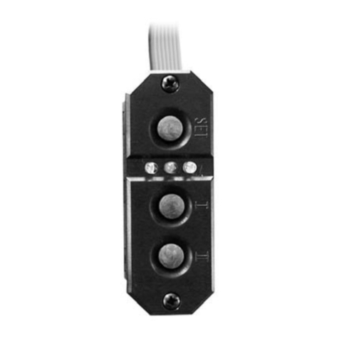
SensorSwitch, which is included in the set. The SensorSwitch is
plugged into the unit for programming, and can then be disconnected
again. When connected to the iGyro, the SensorSwitch has no switching
function for the power supply; it is only used for the adjustment procedure.
The menu control system could hardly be simpler:
- Buttons I and II move the cursor up and down, or alter values.
- The SET-button selects a menu point, and confirms selected values.
A brief press on the SET-button takes you to the menu; you will then
initially see the left-hand screen shot. If you move the cursor right to the
bottom, the right-hand screen display will appear:

-11-
The circular cursor to the left of the menu points turns into a solid disc
when you select a menu point and adjust values.
The main menu can be left again by selecting OK.
4.4. Selecting the radio control system
The PowerBox iGyro must be informed which radio control system you
wish to use, as the bus systems of the various manufacturers differ very
widely. You only need to enter this information once.
The unit’s integral SRS system selects one receiver when switched on,
and automatically switches over to the second receiver if the signal is lost.
Regardless of the type of radio control system employed, the change-over
process takes just a few milliseconds, and is not noticeable to the pilot.
Select the RECEIVER SETTINGS point at the main menu, then press the
SET-button; the following screen display appears:
At this point please select the radio control system you wish to use. With
most receivers it is necessary to activate the Bus output, and / or set the
correct operating mode. Bear in mind the following points:
a) Futaba FASST and FASSTEST:
The iGyro SRS works with the S-BUS signal. Many receivers require one
output to be re-assigned to S-BUS:
- R7003SB: no adjustment necessary; signal present at “PORT 1”.
- R7008SB: output 8 must be set to S-BUS, Mode B or Mode D.
- R6303SB: no adjustment necessary; direct S-BUS output fitted
- R6308SB(T): output 8 must be set to S-BUS, Mode B or Mode D.

-12-
The S-Bus socket fitted to many Futaba receivers is a potential hazard.
The two pictures below illustrate the correct connector position:
Other receivers with an S-BUS output can also be used; please refer to the
set-up notes included in the instructions supplied with the receiver.
b) Spektrum DSM2 and DSMX
If you are using a Spektrum AR 9020, the SRXL output can be used: all
eighteen channels are then available without requiring an X-Plus module.
No adjustments are required: all you have to do is connect the SRXL
output to the iGyro. Once again it is also possible to connect two
receivers.
An alternative option is to connect three Spektrum satellites. This wiring
arrangement is described in greater detail on our Support Forum.
c) Graupner HoTT
When a HoTT system is used, the receivers should first be bound;
adjustments can then be carried out in the Telemetry menu. All receivers
require the CH-OUT-TYPE to be set to SUMD-OF-16.
- GR16 and GR24: SUMD-OF-16 is present at Output 8.
- GR32: SUMD-OF-16 is present at Output S.
d) Jeti
With a Jeti system it is only necessary to set one SAT or EXT output
(depending on the particular receiver) to UDI 16. The remaining
adjustments are carried out using the transmitter’s device manager:
• Serial output: UDI
- Primary settings:
• Signal speed: 10 ms
• PPM settings: Direct
• Failsafe: Inactive (if two receivers are in use; otherwise any setting)
correct incorrect

-13-
e) Multiplex M-LINK
If you are using a Multiplex system, the B/D output at the receiver must be
set to Serial Servo Data SRXL. This can be accomplished using the USB
lead and the MPX Launcher PC program. If you connect two receivers, the
following settings must also be entered: max. hold duration: 0.2 s and
max. Failsafe duration: 0.0 s.
f) JR DMSS
For a JR DMSS system you need receivers with an X-BUS output, e.g.
RG731BX. The receiver or receivers are first bound, then set to MODE A
at the transmitter. The X-BUS output now generates sixteen channels,
which are accessible from the iGyro SRS.
Digital output:
The Digital output can be used in order to connect the iGyro to an SRS
PowerBox or directly to an S-Bus system. If DIG.OUT is set to ON, then
conventional servos cannot be connected directly to the iGyro.
The outputs ELEV-B and RUDDER generate a serial S-Bus signal
output. The output is present at two output sockets, to allow two cables to
be used for additional security.
Important:
you must select the S-Bus option in the TX SYSTEM menu of an SRS
PowerBox, even if, for example, Spektrum satellites are connected to the
iGyro. Power is now fed from the PowerBox to the iGyro and the
receivers connected to it via the two leads.

-14-
4.5. Setup Assistant
Here at PowerBox-Systems we are committed to making high-tech
electronics accessible to all pilots without requiring them to tackle
complicated programming procedures. Our top priority is to make it as
simple as possible to operate the equipment without restricting its
performance.
With the help of the Setup Assistant you should be in a position to set up
the iGyro in ten minutes at most. Once you have completed the basic
settings, only a single flight is required for fine adjustment.
The Assistant covers 99% of all model types. Within certain limits it is also
suitable for thrust vector control systems. For such models the Assistant
can be used to set up the primary functions. The thrust vector control
system itself must then be set up manually. For additional information on
setting up thrust vector control systems please refer to our Support Forum
Before carrying out the set-up flight we recommend that you run the Test
Fly Assistant on the ground several times, to familiarise yourself with the
sequence of operations and the way it works. It is also extremely helpful to
have a fellow-modeller by your side during the set-up flight, as he will be
able to follow the Add-On manual, and keep abreast of the set-up
sequence.
The system also incorporates a safety function, should anything
unexpected occur:
Moving the flight mode switch to the FM1 position disables all the
gyro functions!
The set-up procedure is divided into two sections:
- SETUP ASSISTANT
In this section you select all the model-specific settings, e.g. the gyro’s
orientation in the model, channel assignment, direction of gyro effect.
- TEST FLY ASSISTANT
In this section you adjust the gyro’s gain (sensitivity) while the model is
flying. It is advisable to run this section of the Assistant several times
before flying the model to ensure that you are familiar with the set-up
procedure. Carrying out a ‘dry run’ in this way does not affect the
settings of the SETUP ASSISTANT. However, if you are not confident
of doing this, the alternative is to land the model after setting each value,
and view the gyro’s current status on the integral screen.

-15-
The only preparations you have to make are these:
- Enter the radio control system you wish to use in the RX SETTINGS
menu (Point 4.4)
- Assign a three-position switch and a rotary knob or linear slider at the
transmitter
The next stage is simply to select the Setup Assistant at the iGyro, and
follow the on-screen instructions. The Add-On Manual supplied in the set
shows the sequence of the Setup Assistant, and explains the following
steps.
When the Setup Assistant is complete, you have correctly set the
channel assignments, the gyro’s installed orientation, wing type and
direction of gyro effect. At this point the model should be test-flown
without gyro support, and properly trimmed out.
If your model features a rudder - elevator mixer, or a rudder - aileron mixer,
then it is essential to disable it. If you neglect this, the iGyro will not
operate in Heading mode, since the control surfaces will, of course, be
offset from centre.
You can disable any elevator - landing flap mixer. If you later find that your
optimum gyro gain (established in the air) does not provide sufficient
elevator compensation when landing flaps are deployed, you will need to
activate the mixer again.
Exponential functions can be set up in the usual way, but you may need to
reduce the values slightly when the gyro is active, since the gyro effect
counteracts the control surface function slightly when control commands
are small. This behaviour diminishes as stick deflection increases, and
falls to zero at full stick travel.
Once the model is properly trimmed, you should activate the Test Fly
Assistant in order to find the ideal gyro gain in flight. Once again,
additional information can be found in the Add-On Manual.
Add-On Manual

-16-
4.6. Flächentyp einstellen
When the Test Fly Assistant is complete, the set-up procedure for the
gyro is finished!
5. Experts and manual adjustments
All parameters established using the Setup Assistant can also be
adjusted manually. The system offers a whole series of additional
adjustment options to cater for particular set-ups, such as thrust vector
control systems. It is also possible to adjust the gyro characteristics and
flight modes individually. The following section explains the menu points
and functions available.
5.1. The installed orientation of the iGyro
This setting can be found in the GENERAL SETTINGS menu. To simplify
the process of installing and operating the system, the iGyro must be
informed once of the unit’s orientation in the model after it has been
installed. This procedure makes it possible to use the terms AILERON,
ELEVATOR and RUDDER subsequently in the GYRO SETTINGS menu.
SCREEN refers to the position of the OLED screen in the model; SWITCH
refers to the SensorSwitch socket.
Once you have installed the system in the model, you must enter the
position of the screen and the position of the switch. There are six possible
options for the screen and switch locations.
Add-On Manual

-17-
Here are two examples which should avoid the need for protracted
explanations:
a) The iGyro is installed with the screen on top, and the switch socket
facing the fuselage nose. The correct setting is therefore:
SCREEN: UP/DOWN
SWITCH: BACK/FRONT
b) The iGyro is installed with the screen on top, and the switch socket
facing the wing. The correct setting is now:
SCREEN: UP/DOWN
SWITCH: LEFT/RIGHT
5.2. Selecting the wing type (Mixer)
The iGyro features an integral delta and V-tail mixer. This makes it
possible to exploit the advantages of heading-lock gyro stabilization even
with deltas and V-tail models! This mixer can be activated in the
GENERAL SETTINGS menu point: select DELTA-WING or V-TAIL at the
MIXER point.
Caution: if your model is a delta or features a V-tail, you must not set up
a delta or V-tail mixer at the transmitter. The iGyro carries out the mixing.
The iGyro analyses the aileron and elevator signals from the transmitter,
calculates the deviation according to the sensors, and generates the
signal for both delta control surfaces (elevons).
The mixed delta signals are available at the AILERON-A and
ELEVATOR-A outputs.
In this case ELEVATOR-B is available for functions such as vector control
or a canard system, and can be set up independently.

-18-
The Delta x2 function is intended specifically for models with a delta wing
and a twin thrust vector control system, and allows the thrust vector
system to be operated in combination with a delta mixer. The second delta
mixer is available at outputs AILERON-B and ELEVATOR-B.
5.3. Delta limiter
The default value here is 0%, which means that the elevons (control
surfaces) never run beyond the end-point set at the transmitter, even if the
pilot gives a combined aileron and elevator command equating to full
travel simultaneously. If you set the limiter to a higher value, the calibrated
values can be exceeded accordingly.
This value should be adjusted with the aileron and elevator sticks moved
to full travel: ensure that the servos do not strike their mechanical stops at
any extreme of travel.
5.4. Gyro Sense x4
This option quadruples the gyro effect; this is often necessary with large,
sluggish models in order to obtain the optimum stabilising effect.
Caution: Select this option only if 100% gyro effect is inadequate!
Selecting this option resets all gain settings to 0%!

-19-
5.5. Channel assignment
Modern SRS bus technology makes it possible to assign channels to
particular functions without restriction. The menu point INPUT MAPPING
is used to assign a channel to any function. There are various functions
which can be mapped in this way. In the examples below we show the
method of assigning the ailerons and the flight mode switch:
For example, if you wish to adjust the ailerons again after completing the
settings using the Setup Assistant, you can very simply assign a slider or
rotary knob at the transmitter to the GAIN NORM AILE-A function. With
this arrangement the slider only adjusts the Normal mode of the ailerons.
At the same time you could adjust the Heading value using the same slider
by assigning the same channel to the function GAIN HEAD AILE-A.
Alternatively - if you prefer to adjust the Heading value separately - you
could assign a second slider to Heading gain.
If your model is fitted with two ailerons (or elevators), you should always
assign the same slider to the left and right control surfaces, so that the
Normal or Heading values are adjusted simultaneously.
Example above:
- Channel 2controls the right-hand aileron output
- Channel 11 adjusts the Normal value for the right-hand aileron
- Channel 12 adjusts the Heading value for the right-hand aileron
- Channel 6controls the left-hand aileron output
- Channel 11 adjusts the Normal value for the left-hand aileron
- Channel 12 adjusts the Heading value for the left-hand aileron
Note: with many radio control systems it is advisable to select the slider or
rotary knob at the transmitter, and set that channel’s travel to -105% to
+105%, in order actually to be able to set 0 - 100% gain.

-20-
If you wish to assign a channel, use the SET-button to select the
appropriate function, then move the stick, rotary knob or switch which you
wish to assign. Make sure beforehand that the transmitter control in
question is already assigned to a channel at the transmitter.
Note: automatic detection only works reliably if only one channel per
transmitter control is assigned at the transmitter. For example, if separate
channels are assigned to each aileron at the iGyro, use buttons I and II for
the assignment procedure.
The settings can be checked in the GYRO SETTINGS menu: select the
corresponding axis and move your gain slider or rotary knob: the Gain
display should now vary between 0% and 100%. The flight mode switch
must shift the number following FM between 1 - 2 - 3.
5.6. Settings in the Gyro Settings menu
- AXIS:
At this point you select the axis you wish to adjust. There are 2 x ailerons
(AILE), 2 x elevators (ELEV) and 2 x rudder (RUDD). However, the
second rudder can only be used if the Bus output is active. For example:
in conjunction with an SRS PowerBox, a PowerBus or a Futaba Bus
system.
- FM:
The position of the flight mode switch is displayed at this point.
- Gain Normal:
Here you see the Normal gain setting for the axis you have set up. At this
point it is possible at any time to alter the gain manually using the
SensorSwitch. Changing this value manually automatically erases the
gain channel assignment in the Input Mapping menu.
Table of contents
Other PowerBox Systems Controllers manuals

PowerBox Systems
PowerBox Systems LightBox SR User manual

PowerBox Systems
PowerBox Systems SensorSwitch 6500 User manual

PowerBox Systems
PowerBox Systems voltage regulator User manual

PowerBox Systems
PowerBox Systems Royal SRS User manual

PowerBox Systems
PowerBox Systems 40/16 User manual

PowerBox Systems
PowerBox Systems iESC 65.8 User manual
Popular Controllers manuals by other brands

Think ahead
Think ahead SR-2805ST quick start guide

eMotionLighting
eMotionLighting EML1205 instruction manual

Siemens
Siemens SIPART PS2 Installation instruction

Geotech
Geotech Geocontrol PRO Installation and operation manual

Sentera Controls
Sentera Controls STR-1 Mounting and operating instructions

SEFRAM
SEFRAM SFX+NETWORK TECHNICAL NOTICE