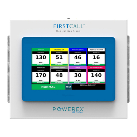
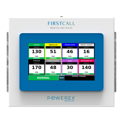
Powerex Med Touch Series User manual

Med Touch Series LCD Alarm Systems
Please read and save these instrucons. Read carefully before aempng to assemble, install, operate or maintain the product described.
Protect yourself and others by observing all safety informaon. Failure to comply with instrucons could result in personal injury and/or
property damage! Retain instrucons for future reference.
Descripon
Powerex • 150 Producon Drive • Harrison, OH 45030 •USA
P 1.888.769.7979 • F 513.367.3125 • www.powerexinc.com
IN597400AV •08/2016
Page 1 of 56
The Powerex Med Touch combinaon area and master alarm
panel digitally displays gas pressure (1 psi increments), monitors and
displays normal and alarm condions from up to 128 remote medical
gas source signals, and provides alarm condions as required by the
latest edion of NFPA 99 for up to 16 medical gases. The alarm is ETL
listed to UL 1069 and CSA C22.2 # 205 Signal equipment. Transducers
& DISS risers are included for area alarm gas boards. Transducers may
be installed remotely or in the back box. Pressure switches and DISS
union check valve connectors are sold separately.
Features & Benets
•Five year parts and one year labor warranty
•2.85” LCD touch screen displays up to 8 normal and alarm
condions for pressure switch sensor inputs
•2.85” LCD touch screen displays up to 8 normal and alarm
condions and provides a digital pressure display for up to 4
transducer sensor inputs
•2.85” LCD touch screen displays normal and high/low alarm
condions for one 4 – 20 mA sensor input
•The LCD touch screen allows all alarm programming and set up to
be done without the use of tools
•A green normal or red alarm condion for each gas services
conrms the condion for each individual gas service
•Emergency preparedness instrucons - Med Touch alarm panels
allow users to set up customized instrucons for each alarm
signal, to appear on the screen when the signal is in alarm
•Up to 128 signal points in a single panel
•Wireless (minimal low voltage wiring) models available (wireless
feature for master signal points only)
•Last event history (per gas board /signal point)
•Made in the U.S.A.
•NFPA and ISO pre-loaded gas ‘labels’
•English, and English/French pre-loaded languages
•Editable text and alarm ‘labels’
•Self-contained unit - Designed for ease of installaon and service
•Self-diagnosc and error message display for ease of maintenance
•Audio and visual alarm indicators
•Bright easy to read LCD displays – clearly visible in both day and
night lighng condions
•Constant display and monitoring of each gas
•User programmable high/low set points on transducer and 4 – 20
mA sensor input boards
•Dry contacts provided on the CPU module for general fault
condion covering enre panel
•Hinged frame for easy accessibility
•Color coded displays
•Alarm history display of previous alarm condions
•Hinged frame for easy accessibility
•Color coded labeling
•Wireless (minimal low voltage wiring) models available
Master Alarm Area Alarm
Combinaon Alarm

Med Touch Series LCD Alarm Systems
Powerex • 150 Producon Drive • Harrison, OH 45030 •USA
P 1.888.769.7979 • F 513.367.3125 • www.powerexinc.com
IN597400AV •08/2016
Page 2 of 56
Addional features:
•Individual user programmable remote signal alarm points to
accept NO or NC signals, or may be disabled. Factory preset to
accept Normally Closed signals.
•LCD indicators (Green) conrms normal status, (Red) indicates
abnormal condion.
•Menu of NFPA 99 master alarm signals for quick, easy selecon.
•Gas specic transducer master signal boards. An error message
will be displayed if incorrect sensor or no sensor is aached.
•Transducer master signal boards shall be capable of displaying
gas readouts in PSI, kPa, BAR, inHg, or mmHg.
•Alarm repeat feature is factory set at 10 minutes, and is adjustable
or may be turned o.
•User programmable high/low set points on transducer master
boards.
In addion, each Area Alarm Module shall incorporate the following
features:
•Does not require re-calibraon.
•Gas specic sensor with DISS nut & nipple. An error message will
be displayed if incorrect sensor or no sensor is aached.
•Shall be capable of displaying gas readouts PSI, kPa, BAR, inHg, or
mmHg.
•Gas alarm repeat feature is factory set at 10 minutes, and is
adjustable or may be turned o.
The following opons shall be able to be added to the panel at the
me of order or aer installaon;
•Oponal Ethernet module. This module may be added to any
alarm panel. It will provide the following features:
•Webserver – allows a remote user access to the alarm’s
webpage – viewing a graphic image of the alarm with all
signal condions, pressure & event / history log informaon.
•Text nocaon of alarm condions (up to 5 addresses).
•Event / history log – maintains a rolling list of the 100 most
recent alarm condion events and a le of the 1,000 most
recent alarm events and is downloadable through embedded
web pages.
•Modbus interface with Ethernet connecvity.
• Oponal BACnet module. Available for master and area/master
combinaon alarms only. The Ethernet module must be installed
in the alarm to use the BACnet module. Will provide the following
features: provides a Modbus to BACnet gateway to interface
to a BACnet building management system through Ethernet
connecvity.

Med Touch Series LCD Alarm Systems
Powerex • 150 Producon Drive • Harrison, OH 45030 •USA
P 1.888.769.7979 • F 513.367.3125 • www.powerexinc.com
IN597400AV •08/2016
Page 3 of 56
Contents
Features & Benets 1
Introducon 4
Major components 5
Alarm Installaon 6
Rough-In Box Installaon 6
Wiring/AC 6
Plumbing the Riser Extension Tubes 6
Installing the Hinges 8
Installing the Alarm Front Panel 8
Wiring the Alarm Front Panel 8
Installing the Transducers (Non-Remote) 9
Installing the Transducers (Remote) 9
Connecng Transducer Wiring to the Alarm Front Circuit Board 9
Wiring the Remote Devices (Dry Contacts) 10
Wiring the Remote Devices (Transducers) 11
Wiring the Remote Devices (4-20mA) 12
Wiring General Fault (Dry Contacts) 12
Power On 13
Alarm Displays & Funcons 14
Buon Module Displays & Funcons 14
Gas Module (Area Alarms) 15
Alarm Condions 15
Emergency Instrucons (Gas Module) 15
Master Remote Signal (Dry Contacts) 16
Emergency Instrucons (Master Modules) 16
Master Remote Signal (Transducer Inputs) 16
Master Remote Signal (4-20 mA Input) 16
Alarm Operaon 17
Silencing the Alarm 17
Repeater Delay 17
Tesng the Alarm 17
Gas (Area) Modules 17
Master Remote Signal (Dry Contacts) 17
Master Remote Signal (Transducer Inputs) 17
Master Remote Signal (4 – 20 mA Input) 17
Ethernet Module 17
BACnet Gateway Module 18
Programming the Alarm 18
Accessing the Alarm Program Mode 18
Programming High & Low Alarm Pressure Set Points 19
Programming Remote Signal Master Points (NO or Disable) 19
Programming Remote Signal Master Points (NFPA Labels) 19
Programming the Repeater Delay 20
Programming the Units of Measure 23
Adjusng the Digital Pressure Calibraon 20
Programming the Board Com ID 20
Programming the Gas Service (Area Alarm) 21
Programming Language & Latching/Non-Latching Alarm Relays 21
View Screen 21
Programming Text & E-Text Gas (Area Alarm) 22
Programming Text & E-Text Master (Dry Contacts) 22
Programming 4-20mA Master Module 23
Programming the Equipment Name 23
Installing Ethernet/Rabbit Boards 24
Create Receive Connector 25
Programming the Ethernet/Rabbit Board 27
E-mail & Text Nocaons 30
Rabbit Board Programing Commands 32
Modbus Interface 33
Website Access 33
BACnet Interface 35
Appendix A Glossary of Terms 39
Appendix B Alarm Specicaons 40
Appendix C Master Signal Wire Log 41
Appendix D Master Alarm Signal Lisng 42
Appendix E Wiring Diagram (AC & DC) 43
Appendix F Wiring Diagram Area Alarm Remote Transducers 44
Appendix G Wiring Diagram (Master Equipment) 45
Appendix H Wiring Diagram (Master Remote Transducer) 46
Appendix I Wiring Diagram Master 4-20mA Signals 47
Appendix J Wiring Diagram Ethernet Communicaon 48
Appendix K Wiring Diagram (AC and DC) BACnet 49
Appendix L Wiring Diagram BACnet Communicaon 50
Appendix M Text Message Carriers 51
Appendix N Ethernet/Rabbit Board Programming Log 54
Terms & Warranty 56
Technical Assistance 1-888-769-7979

Med Touch Series LCD Alarm Systems
Powerex • 150 Producon Drive • Harrison, OH 45030 •USA
P 1.888.769.7979 • F 513.367.3125 • www.powerexinc.com
IN597400AV •08/2016
Page 4 of 56
Introducon
This manual covers the installaon and operaon of the Powerex
“T” series of Med Touch Alarm Systems. It applies to three dierent
back boxes and front panel sizes that are described as 2 slot, 3 slot,
and 5 slot. These panels can have a maximum of 4 modules in a 2
slot alarm, 8 modules in a 3 slot alarm, or 16 modules in a 5 slot
alarm. Refer to our Submial Data Sheet 99-0488 for Master Alarms,
99-0489 for Area Alarms and 99-0490 for Combinaon Alarms for
details on the physical size and module opons in each of these Alarm
Systems. These can be found on our website at www.powerexinc.com
and look under Pipeline Products to nd the type of Med Touch Alarm
Submial Data (Specicaon) sheet needed.
The Powerex gas alarm system monitors the status of the medical
gas distribuon system and provides audible and visual indicators.
The master alarm can be furnished with either Ethernet or MCP
building management interface circuit board(s) to communicate
status informaon to the building management system. Any type of
alarm may be equipped with an oponal Ethernet board which will;
launch a website, send text nocaons to ve addresses, maintain
a rolling history / event log of 100 recent events and a le of 1,000
events, and provide a Modbus interface. A BACnet interface opon
may be added to any master alarm with the Ethernet opon. The
Powerex alarm system monitors the status of the medical gas sources
in accordance with NFPA 99 and CSA Z7396.1.
The Powerex gas alarm system is an assembly comprised of a rough-
in box, a front panel and transducers (if it is an area, combinaon or
transducer master alarm).
improved safety (an alarm is immediately triggered when a transducer
fails), greater accuracy / repeatability, ease of seng (push buon vs
mechanical adjustment) and lower cost in most cases.
The Remote Signal 4 – 20 mA contacts module monitors a single
4 – 20 mA sensor. The user is able to program and name the units of
measure represented by the bar graph generated by the module. The
user is also able to set the high and low alarm set points
Rough-in Box
The rough-in box houses the
power supply, fuse, on/o switch,
and a terminal strip for electrical
wiring. An isolated transformer
reduces the 110V or 220V AC input
to low voltage DC.
Front Panel
The front panel includes enclosed
printed circuit boards with
programming circuitry.
The Push Buon module includes
a power on indicator, quick view
informaon buons, the silence
buon and an audible alarm.
The Remote Signal dry contacts
module(s) can monitor up to 8
signals per circuit board. Mulple
remote signal modules can be
The Remote Signal transducer
contacts module(s) can monitor
up to 8 signals from 4 transducers
per circuit board. Mulple remote
signal modules can be ordered in
a single alarm which would be in
communicaon with transducer
sensors. The signals can be
congured to display an abnormal
condion on either a normally closed
(NC) or a normally open (NO) circuit.
Each signal may also be turned o if
it is not being ulized. The benets
of transducers over dry contacts are:
The Gas (Area) module(s) on the
front panel are idened with gas
specic, color coding (per NFPA 99
or CSA Z7396.1). The display shows
the actual gas pressure along with
an indicaon of the pressure being
within the Normal, High or Low
pressure range. The gas pressure
may be displayed in PSI, In Hg, BAR
or kPa. The unit is pre-programmed
to display PSI / In Hg from the
factory, but may be re-programmed
in the eld to display BAR or kPa. In
addion the display will indicate System and Program failures. Each
module is supplied with dry contacts for remote signaling of high and
low pipeline pressure.
supplies the electrical signal to the
alarm Gas and/or Remote signal
transducer modules. Aer the inial
24 hour 150 psi standing pressure
test (required per NFPA 99) has
been completed the pressure/
Transducers
The transducer converts pressure to an electrical signal and
ordered in a single alarm which would be in communicaon with dry
contact sensors. The signals can be congured to display an abnormal
condion on either a normally closed (NC) or a normally open (NO)
circuit. Each signal may also be turned o if it is not being ulized.
vacuum transducers may be connected to the medical gas pipeline.
The transducers may be remotely aached to the piping system at
distances up to 5,000 feet using standard 18 gauge stranded twisted
pair wire. Powerex recommends mounng the transducers in the
zone appropriate zone valve box (ulizing the Powerex E Z Backfeed™
and E Z Find™ features) or in the alarm back box. Should a transducer
require service or replacement it is considerably more of a safety

Med Touch Series LCD Alarm Systems
Powerex • 150 Producon Drive • Harrison, OH 45030 •USA
P 1.888.769.7979 • F 513.367.3125 • www.powerexinc.com
IN597400AV •08/2016
Page 5 of 56
issue and more me consuming to locate and replace transducers
which have been remotely located above the ceiling and eliminates
contaminaon issues – such as having to set up a tent in order to
remove ceiling les.
Risers
DISS x ½ O.D. tube gas specic
risers with our Frontall™ front
loaded check valve are provided for
each gas service corresponding to
the gas boards ordered in an area or combinaon alarm. The risers
may be installed in the alarm back box or remotely on the pipeline.
Rough-in or back box with power supply Front Panel with circuit boards
Transducers Risers

Med Touch Series LCD Alarm Systems
Powerex • 150 Producon Drive • Harrison, OH 45030 •USA
P 1.888.769.7979 • F 513.367.3125 • www.powerexinc.com
IN597400AV •08/2016
Page 6 of 56
Alarm Installaon
Installaon of the Powerex alarm involves installing the rough-in
box, the risers & the transducers (if it is an area alarm or combinaon
alarm) and front panel and making the necessary conduit, plumbing
and electrical connecons. All installaon and tesng should be done
in accordance with NFPA 99 or CSA Z7396.1.
Electrical power intended for the alarm to
be installed should be disconnected prior to
installaon.
This device should only be installed by qualied
personnel. Installaon should not be aempted by
anyone not having general experience with the installaon of devices of
this nature.
Rough-in Box Installaon
This is a rough-in box for a
combinaon alarm. Your rough-
in box should look the same or
similar to this unit. The risers are
shipped loose, for protecon during
shipment, and must be installed.
If transducers are to be mounted
remotely, it is recommended that
they be connected to the DISS
demand check valves installed in
the corresponding zone valve box
equipped with the Powerex E Z
Backfeed™ and E Z Find™ features.
Refer to the building plans to determine the locaon of the alarm.
The contractor is to provide rigid
mounng that will support the
alarm box on both sides. The metal
anges provided on both sides of
the rough-in box are to rest against
the rigid mounng brackets. Screws
(contractor provided) are to be
driven thru the holes in the metal
anges into the mounng brackets.
Flanges are adjustable to allow for a
drywall depth of 1/2” to 1 1/8”.
Mount alarm rough-in box so it will
be ush or just below the nished
wall surface using the adjustment
feature on the anges.
Side/end view of rough-in back box
The power supply hole is located in the boom (le side) of the
rough-in box. Remove the plaster cover and panel covering the
power supply. Make conduit connecons for wiring from the facility
emergency power source.
To remove the power supply cover, loosen the two screws at the
top of the cover and slide the cover to the right, then li the cover
over the screw heads. Slide the wiring harness strain relief to the le
unl it is free from the cover.
Wiring
Use either of the two ½” conduit knock-outs provided on the lower
le side and boom of the rough-in box to route conduit to supply
either 120 or 240 VAC to the power supply. Note: Separate conduit
should be used for low voltage wires (use knock outs provided on the
top of the box). Low voltage signal wiring must be run at least 6 inches
away from high voltage wiring (90VAC or greater)
When necessary to cross low and high voltage wiring, maintain
minimum 6 inch spacing and cross as close to 90° as possible.

Med Touch Series LCD Alarm Systems
Powerex • 150 Producon Drive • Harrison, OH 45030 •USA
P 1.888.769.7979 • F 513.367.3125 • www.powerexinc.com
IN597400AV •08/2016
Page 7 of 56
Route wires through the power supply conduit installed in the
boom and le side of the rough-in box. Connect the 120 or 240 VAC
facility emergency power source electrical wiring to the terminal strip
provided on the lower le side of the box. (N = neutral, L = Line (hot),
FG = eld ground).
The wiring harness will be provided pre-wired to the power supply.
If by chance you are replacing a wiring harness, the single green
ground wire should be fastened to the screw on the top le corner of
the power supply board. The wiring plug in connector (which should
contain the rest of the wires), plugs into the connector terminal on
the upper le corner of the power supply board. The black wire will
be on the top.
This is how the power supply should look when the wiring is
completed.
Replace the power supply cover and plaster cover (to protect the
unit while the drywall and wall covering work are being done) aer
wiring is complete.
Plumbing the Riser Extension Tubes
Install the risers in the top of the
back box as shown.
Aer removing the protecve
plasc caps, connect the riser
extension tubes to the gas piping
system per NFPA 99. Make sure
the drop is for the proper gas
service. Using a purge gas to insure
cleanliness in the tubes, silver braze
the joints. Do not use so solder.
Conduct heat away from the check
valves. (Per NFPA 99 Chapt 5 a
nitrogen purge is required). The 150
psi standing pressure test of the
piping system must be successfully
completed and all pressure removed
from the system before connecng the transducers to the system.
Aaching transducers without depleng the 150 psi standing
pressure rst will result in damage to the transducers!
NOTE: It is recommended that gas piping system tubing be
connected from the riser extension tube to the ceiling for a future or
blank gas display even though a transducer is not being installed. Cap
the unused tube above the ceiling. This will simplify future expansion.
AU89xx series riser extension tubes are sold separately.
NOTE: It is also possible to install the transducers remotely (not in
the alarm box). In this type of installaon the risers are connected to
the gas piping system up to 5,000 feet away from the alarm panel.
NOTE: Powerex recommends mounng the transducers either in
the zone valve box (remote) in conjuncon with the EZ Backfeed™ and
EZ Find™ products or in the alarm back box – not remotely above the
ceiling. Should a transducer require service, tesng or replacement it
is considerably more me consuming to locate and replace or service
transducers remotely located above the ceiling.
Neutral
Line (Hot)
Field Ground
Riser extension tubes
½ inch O.D. tube

Med Touch Series LCD Alarm Systems
Powerex • 150 Producon Drive • Harrison, OH 45030 •USA
P 1.888.769.7979 • F 513.367.3125 • www.powerexinc.com
IN597400AV •08/2016
Page 8 of 56
Installing the Hinges
Aer the walls are nished, the hinges may be installed onto the
rough-in box. The two hinges should be fastened to the lower front
edge of the rough-in box using the screws provided. The hinge should
rest at against the surface of the drywall.
Installing the Hinges
The alarm front panel snaps onto the two hinge pins. If the hinge
gets detached from the front panel, simply snap it back on.
Aach the two (le & right side) lanyard cables to the alarm back
box and (if necessary) front panel using the screws provided.
Wiring the Alarm Front Panel to the Power Supply
Aach the green ground wire, which is in the wiring harness, to
the ground stud on the le side of the front panel – near the le rear
corner of the buon board.
Aach the plug connector at the end of the wiring harness to the
appropriate connector located at the top le corner of the buon
module circuit board. The plug should lock into place. The plug can
only be inserted one way.
This is how the wiring harness plug connector should look when
properly installed on the back of the buon module board.

Med Touch Series LCD Alarm Systems
Powerex • 150 Producon Drive • Harrison, OH 45030 •USA
P 1.888.769.7979 • F 513.367.3125 • www.powerexinc.com
IN597400AV •08/2016
Page 9 of 56
Installing the Transducers (Non-Remote)
Aer depressurizing the 150 psig standing pressure from the piping
system, install the appropriate transducers to the appropriate riser
extension tube connectors inside the rough-in box. Hand-ghten,
then torque lightly with a wrench.
Installing the Transducers (Remote)
Transducer assemblies with DISS gas specic ngs have also been
provided and, aer the 24 hour standing pressure test is completed
and normal operang pressure has been restored to the medical gas
piping system, they must be connected to the DISS demand valves.
Note: maximum mounng distance of each remote transducer is
5,000 feet away from the alarm panel to which it will be wired. Follow
the wiring instrucons in Appendix F.
The transducers have been designed so that they may be installed in
a standard 4”x 4”x 2 1/8” electrical juncon box for added protecon.
A panel mount feature has been provided to allow mounng of
the transducer using standard 1/2”conduit connecons and 4”x 4”x
2 1/8” juncon boxes. Note: The DISS nut & nipple will need to be
removed to allow installaon of the conduit nut and then re-installed
using oxygen safe Teon tape.
Care should be taken to not allow debris of any type to enter the
transducer during the removal & re-installaon of the DISS nut &
nipple as this may prevent the transducer from funconing properly.
Connecng the Transducer Wiring to the Alarm Front Circuit
Board
The wire terminal connector on the gas board has six wire
connecon slots. The two wires from the transducer should be
installed in the BLK & WHT SENSOR slots. These are the two slots
closest to the center of the gas board (as shown). If the transducer is
installed remotely and addional wire is used, it is preferred that the
wire polaries remain the same even if the wire colors are changed.

Med Touch Series LCD Alarm Systems
Powerex • 150 Producon Drive • Harrison, OH 45030 •USA
P 1.888.769.7979 • F 513.367.3125 • www.powerexinc.com
IN597400AV •08/2016
Page 10 of 56
The other four connecon slots are for oponal remote monitoring
of the low and high line pressure alarms on a master alarm, building
management system, or other device.
The other four connecon slots are for oponal remote monitoring
of the low and high line pressure alarms on a master alarm, building
management system, or other device.
There are a total of 6 connecon points – the rst two connecon
points are for the transducer sensor, the next two points are for
the low line pressure alarm and the last two points are for the high
pressure alarm. The low and high line pressure contact sets provide a
normally closed set of contacts and consis of a normally closed (NC)
and a common (C) connecon.
Visually verify that the appropriate transducer wire pair has been
aached to the appropriate gas module by looking at the front of the
alarm panel. If there is not an Error Condion and a System alarm,
the proper (matching gas service) transducer has been connected to
the gas board.
Wiring the Remote Devices to Remote Signal Master Board
(Dry Contacts)
Locate the two banks of 8 terminal connectors on the back of the
remote signal (master) board.
Inputs 1 thru 4 are on the le edge of the board and 5 thru 8 are on
the right edge of the board.
There are a total of 16 connecon points – two connecon points
for each remote signal. The pairs are labeled 1 IN thru 8 IN on the
circuit board. The NC (normally closed) labeled terminal of each pair
is where the signal wire should be landed. The C (common) labeled
terminal of each pair is where the common wire should be landed.
Note: it is required that polarity be maintained between the switch
being monitored and the master alarm.
The transducer plug may be removed from the gas module to make
it easier to install the wires.

Med Touch Series LCD Alarm Systems
Powerex • 150 Producon Drive • Harrison, OH 45030 •USA
P 1.888.769.7979 • F 513.367.3125 • www.powerexinc.com
IN597400AV •08/2016
Page 11 of 56
The connector terminal may be un-plugged from the circuit board
to simplify installaon of the remote signal wires.
Land the corresponding signal on the NC (normally closed) &
common wires on the C (common) terminal of each pair of terminal
connectors. It is imperave that the signal wires are landed in the NC
posion and that the common wires are landed in the C posion.
Wiring the Remote Devices to Remote Signal Master Board
(Transducer Sensors)
Locate the bank of 8 terminal connectors on the le edge of the
back of the remote signal (master) board.
There are a total of 8 connecon points – two connecon points
for each transducer sensor. The pairs are labeled 1 IN thru 4 IN on
the circuit board. The white wire from the transducer should be
landed in the WHT posion and the black wire from the transducer
should be landed in the BLK posion. Note: only Powerex D and T
series alarm transducers are compable with the Med Touch alarm
system.
Remote Signal #1
Common Wire Signal #1 Remote Signal #2
Common Wire Signal #2
The connector terminal may be un-plugged from the circuit board
to simplify installaon of the remote signal wires.
The sequence in which the transducers are connected to the board
correspond with the order in which they will appear on the display.
The #1 transducer will be displayed on top and the #4 transducer will
be displayed on the boom. There will be up to two display posions
(high line pressure and low line pressure) for each transducer.
Transducer #1 White
Transducer #1 Black Transducer #2 White
Transducer #2 Black

Med Touch Series LCD Alarm Systems
Powerex • 150 Producon Drive • Harrison, OH 45030 •USA
P 1.888.769.7979 • F 513.367.3125 • www.powerexinc.com
IN597400AV •08/2016
Page 12 of 56
Wiring the Remote Devices to Remote Signal Master Board
(4-20mA Transmiers)
Locate 3 port terminal connector on the right edge of the back of
the remote signal (Master) board.
The terminal connector will be labeled 4-20mA.
The terminal connector may be un-plugged from the circuit board
to simplify installaon of the wires.
For 4-20mA transmiers with loop power supplied by an external
source.
Land the 4-20mA signal wire in the Number 2 terminal port. Land
the (-) ground wire to the Number 3 terminal port.
For 4-20mA transmiers with loop power supplied by the Alarm
Circuit Board (35-0037)
Land the 4-20mA signal wire to the Number 2 terminal port. Land
the +12VDC wire to the Number 1 terminal port.
Wiring General Fault Dry Contacts to Building Automaon
System or Remote Alarm
The buon board (shown here) is located in the top le corner of
the alarm panel. The dry contacts which provide the general fault
alarm condion are located on the boom edge of the board.
Normally Open (NO), Normally Closed (NC) and Common (C)
connecons are provided.
The terminal connector may be un-plugged from the circuit board
to simplify installaon of the remote signal wires.

Med Touch Series LCD Alarm Systems
Powerex • 150 Producon Drive • Harrison, OH 45030 •USA
P 1.888.769.7979 • F 513.367.3125 • www.powerexinc.com
IN597400AV •08/2016
Page 13 of 56
Power On the Alarm
You are now ready to supply power to the alarm. Restore power to
the circuit feeding this alarm panel. The toggle switch on the front of
the power supply should be placed in the ON posion.
Check the green power LED indicator on the front of the buon
module. It should be illuminated.
If you haven’t already, you are now ready to pressurize the piping
system to normal operang pressures. The alarm is shown here with
Medical Vacuum at normal operang pressures. All remote signal
points (master alarm signals) are shown in normal condion.

Med Touch Series LCD Alarm Systems
Powerex • 150 Producon Drive • Harrison, OH 45030 •USA
P 1.888.769.7979 • F 513.367.3125 • www.powerexinc.com
IN597400AV •08/2016
Page 14 of 56
Alarm Displays & Funcons
Buon Module
Power on Indicator
The power on indicator (green LED) is illuminated whenever
electrical power (120 or 240 VAC) is connected to the alarm and
the on/o switch is turned on.
Test Buon
When the Test buon on the front panel is pressed, the alarm
illuminates all segments of all lights and LED’s and sounds the
buzzer.
Alarm Silence
In the event of an alarm condion an audible alarm sounds. The
audible alarm can be silenced by pressing the alarm silence buon.
The alarm will alternate displaying the rooms/area monitored
with the emergency instrucons unl the alarm condion is
reced. Depressing the silence buon will silence the alarm for
approximately 10 minutes (factory seng). Aer approximately 10
minutes, the audible alarm will sound again. (See alarm operaon
secon on page 17 for more detail).
View Last Event Alarm History Buon
The Last Event History buon may be pressed and held at any
me to view last event alarm history. Viewing alarm history is only
acve while the Last Event History buon is pressed, releasing the
buon returns the alarm to normal operaon. Pressing the Last
Event History Buon will display the following:
Gas (Area) and Remote Signal Transducer Modules – The High
and/or Low Pressure indicaon will be displayed along with the
actual highest or lowest pressure which occurred.
Remote Signal (Master) Module – If there was an alarm condion
for any Remote Signal the Red LCD will be illuminated. All other
LCD’s will be o.
4-20 mA Module – The High and/or Low value indicaon will be
displayed along with the actual highest or lowest value which
occurred.
Clear Last Event Alarm History Buon – To clear Last Event Alarm
History you simply press the Clear History buon.
▲ (up arrow)
The up arrow may be pressed & held at any me to display the
high line pressure alarm set points of the gas module (area) boards,
the remote signal transducer boards and the 4 – 20mA boards.
▼ (down arrow)
The down arrow may be pressed & held at any me to display the
low line pressure alarm set points of the gas module (area) boards,
the remote signal transducer boards and the 4 – 20mA boards.
► (right arrow)
The right arrow may be pressed & held at any me to display the
gas service for which the gas modules (area) boards are currently
programmed. (See list on page 15).
◄ (le arrow)
The le arrow may be pressed & held at any me to display the
type of transducer that is connected to each gas module (area)
board. The 3 types are 0 – 30 In Hg, 0 – 100 psig and 0 – 250 psig.
When the le arrow is pressed “30” will be displayed for a 0 – 30 In
Hg transducer, “100” will be displayed for a 0 – 100 psig transducer
and “250” will be displayed for a 0 – 250 psig transducer.
Alarm Silence buon
Clear Last Event
History buon
View Last Event
History buon
Test buon
Power On Indicator

Med Touch Series LCD Alarm Systems
Powerex • 150 Producon Drive • Harrison, OH 45030 •USA
P 1.888.769.7979 • F 513.367.3125 • www.powerexinc.com
IN597400AV •08/2016
Page 15 of 56
Gas Module (Area Alarms)
Other Possible Condions
Other possible system condions
may occur in the event of a wiring
problem, sensor problem or board
malfuncon. The following codes will
be displayed when a System Error or
Failure is detected, or when the View
Recent History buon is pressed:
Alarm Reason
No Sensor Sensor wire(s) not connected
No Sensor Data No data sent within alloed me
Bad Sensor Data Corrupt data, sensor noise
Wrong Gas Type Mismatched sensor and gas board
Wrong Pressure
Range
Sensor does not match gas board sensor
selecon
Low Pressure Pressure is below low alarm set point
High Pressure Pressure is above high alarm set point
Gas Service
(see programming – page 26)
Gas Pressure
The LCD Digital Pressure Display displays the pressure as indicated
by the transducer. The gas pressure may be displayed in PSI, kPa,
BAR, inHg, or mmHg. PSI and inHg is the factory seng.
NOTE: Vacuum & EVAC/WAGD may be displayed as inHg or mmHg.
Only the applicable unit selecon buons will be acve based
on the gas service selected. For example - the PSI, kPa and BAR
selecon buons will be displayed but are not acve when a
negave pressure gas has been selected. In kPa mode the Nitrogen
gas display indicates one tenth of the actual pressure when the
pressure exceeds 999 kPa (i.e. 1100 kPa is displayed as 110 and the
kPa and (x 10) appears in the pressure text box.
NOTE: Alarm sengs are maintained even if power is interrupted.
Units of Measure
The Units of Measure is displayed as PSI/inHg, BAR or kPa
(whichever is selected during programming – PSI and inHg is factory
seng) providing the unit of measure displayed on the LCD pressure
reading. In the kPa mode the Nitrogen gas display indicates one
tenth of the actual pressure when the pressure exceeds 999 kPa
(i.e. 1100 kPa is displayed as 110 and the kPa and (x 10) appears in
the pressure text box.
High/Normal/Low Condion Status
Should the line pressure of a gas exceed the programmed alarm
set points for low or high line pressure, the corresponding low or
high line pressure LCD will be illuminated simultaneously with the
buzzer sounding to announce an alarm condion has occurred.
When the line pressure is neither high nor low it is considered
within the normal range and the green Normal LCD is illuminated.
These indicaons are relave to the high and low pressure set
points which have been programmed into the alarm. These high
and low set points should be set in accordance with NFPA 99 at ±
20% of the normal operang pressure.
Rooms/Area Covered & Alarm/
Emergency Instrucons
When in the Normal Condion, the
rooms / area covered informaon
which has been entered by the
user is displayed. When in an alarm
condion, the emergency instrucons
which have been entered by the user
are displayed alternately with the
rooms/area monitored informaon.
In addion the display will ash on
and o. (see Programming Text – page
27).
NOTE: This table covers all alarm modules used in both area &
master alarm panels.
Gas Service
Gas Pressure
Units of Measure
Condion
Room/area covered &
alarm/emergency instrucons

Med Touch Series LCD Alarm Systems
Powerex • 150 Producon Drive • Harrison, OH 45030 •USA
P 1.888.769.7979 • F 513.367.3125 • www.powerexinc.com
IN597400AV •08/2016
Page 16 of 56
Master Remote Signal (Dry Contacts)
Emergency instrucons may also be input (by the user) for each
of the signal points. The normal display will appear and react
just like a convenonal remote signal master dry contact display
(shown on the le side of this page), but a touch of the display
will change the display (for 30 seconds) to look and react similar to
an area alarm gas display (photo at right). The advantages of using
transducers over pressure switches are;
• Digital display of actual gas pressure
• Greater accuracy / repeatability
• Improved safety (an alarm condion nocaon is created
immediately should a transducer fail)
• Easy / fast push buon re-seng of alarm set points
• Lower cost (in most cases)
Master 4-20 mA Remote Signal
Monitors the status of a source of the medical gas distribuon
system (i.e. – liquid level of bulk oxygen) in communicaon with
one 4 – 20 mA signal input generate and display a bar graph with
user dened units, provide high & low alarms with user dened
set-points and provide the emergency instrucons (programmed
by the user). Other applicaons may include monitoring ow rates,
levels, concentraons, humidity, etc.
Master (dry contact) modules will provide up to 8 alarm signals
when used in communicaon with dry contact sensors. For each
signal point a ‘label’ must be selected from a pre-loaded database
of NFPA 99 master alarm signals. You also have the opon of
creang your own ‘label’. Emergency instrucons may also be input
(by the user) for each of the signal points. The master boards are
pre-programmed with all signal points programmed NC (normally
closed). There is an alarm condion indicator for each signal point.
The alarm condion indicator will be green when the signal is in
a normal state and red when in an alarm state. When an alarm
condion occurs in addion to the condion indicator turning red,
the signal will ash on and o and the emergency instrucons will
alternate being displayed with the alarm signal label.
Master Remote SIgnal (Transducer Contacts)
Master (transducer contact) modules will provide up to 8 alarm
signals when used in conjuncon with Powerex transducer sensors.
For each signal point a ‘label’ must be selected from a pre-loaded
database of NFPA 99 master alarm signals. You also have the opon
of creang your own ‘label’.
Alarm Labels
Alarm Condion
Indicators
Emergency Text
(displays in red)
Gas Service
Gas Pressure &
Units of Measure
Condion
Alarm Signal #2
Alarm Signal #1
User-entered
Equipment Name
User-entered
Numeric Value for
20mA
Scaled Bar Graph
User-entered
Text & E-text
User-entered
Numeric Value
for 4mA
User-entered
Units of Measure
Scale Reading

Med Touch Series LCD Alarm Systems
Powerex • 150 Producon Drive • Harrison, OH 45030 •USA
P 1.888.769.7979 • F 513.367.3125 • www.powerexinc.com
IN597400AV •08/2016
Page 17 of 56
Alarm Operaon
This secon deals with the daily operaonal aspects of the alarm panel. Aer installaon has been completed and the nal user programming of the panel has been properly
congured, it is ready for operaon.
Silencing the Alarm
Press the Silence buon when the alarm is sounding and the alarm
will be silenced.
Repeater Delay
Area alarm modules are programmed with a Repeater Delay feature
which monitors only the Gas Module (Area) alarms. The Repeater
Delay has been factory programmed to make the alarm re-sound
every 10 (ten) minutes as long as the alarm condion exists.
NOTE: The repeater delay may be re-programmed to a dierent
duraon or turned-o (see programming page 25). Master remote
signal modules may be programmed by the user with the same
repeater delay feature (see programming page 25).
Tesng the Alarm
Pressing and holding the Test buon iniates a self-test of the alarm.
All LCD’s will illuminate for as long as the Test buon is depressed. In
addion the buzzer will sound. If any LCD is faulty the circuit board
should be replaced. If the buzzer does not sound, it is faulty and the
circuit board should be replaced.
NOTE: The alarms (both Area & Master) have a lter programmed
to ignore transient signals that are less than 0.7 seconds in duraon.
Area Alarm Gas Modules
Monitor the status of the medical gas ‘areas’ of the facility. Gas
modules communicate with transducers and provide: 1) the pressure
readings of the gas on each gas display 2) the Normal LCD (green) or
Alarm Condions LCD (red) on each gas display and 3) the emergency
instrucons (programmed by the user).
If the pressure of one of the gases drops below the programmed
low limit seng, the following events take place simultaneously: 1)
the Normal LCD will be exnguished 2) the Pressure Low LCD (red)
will illuminate 3) an audible alarm will sound 4) the emergency
instrucons will be displayed alternately with the pressure low (red)
alarm display if they have been programmed by the user.
If the pressure of one of the gases rises above the programmed
high limit seng, the following events take place simultaneously:
1) the Normal LCD will be exnguished 2) the Pressure High LCD
(red) will illuminate 3) an audible alarm will sound 4) the emergency
instrucons will be displayed alternately with the pressure high (red)
alarm display if they have been programmed by the user.
Master Remote Signal (Dry Contacts)
Monitor the status of the sources of the medical gas distribuon
system in communicaon with the remote equipment dry contacts
connected to it and provide the emergency instrucons (programmed
by the user).
The remote signals (master) module displays (via green or red
indicators) the normal/abnormal status of the remote equipment
connected to the alarm. All alarm panels are pre-programmed upon
leaving the factory to monitor normally closed signals (per NFPA
99). In normal operaon all acve signals will be green. Whenever
an abnormal status signal is detected the corresponding green LCD
will be exnguished and the red LCD will illuminate. Simultaneously
an audible alarm will sound. Pressing the Silence buon silences
the audible alarm (the Red LCD connues to be lit). Emergency
instrucons will be displayed alternately with the signal point text if
they have been programmed by the user. The appropriate personnel
should be noed immediately of the alarm condion. When the
alarm condion has been reced the Red LCD is automacally
exnguished and the Green LCD illuminates.
NOTE: Master alarm signals shipped programmed to not repeat –
but may be re-programmed (see page 20) to repeat incorporang
the Repeater Delay feature.
Master Remote Signal (Transducer Inputs)
Monitor the status of the sources of the medical gas distribuon
system in communicaon with the transducers connected to it (up
to 4) and provide the emergency instrucons (programmed by the
user).
The standard display will appear and react just like the convenonal
remote signal master dry contact displays that the industry is used
to (reference page 20), but a touch of the display will change the
display (for 30 seconds) to look and react just like the convenonal
area alarm gas display that the industry is used to (reference page
20). The advantages of using transducers over pressure switches are;
• Digital display of actual gas pressure
• Greater accuracy / repeatability
• Improved safety (an alarm condion nocaon is created
immediately should a transducer fail)
• Easy / fast push buon re-seng of alarm set points
• Lower cost (in most cases)
Master 4 – 20 mA Remote Signal
Monitors the status of a source of the medical gas distribuon
system (i.e. – liquid level of bulk oxygen) in communicaon with
one 4 – 20 mA signal input generate and display a bar graph with
user dened units, provide high & low alarms with user dened set-
points and provide the emergency instrucons (programmed by the
user). Other applicaons may include monitoring ow rates, levels,
concentraons, humidity, etc.
Ethernet Module
This oponal module may be added to any alarm panel. It will
provide the following features:
• Webserver – allows a remote user access to the alarm’s web
page – viewing a graphic image of the alarm with all signal
condions, pressure and event / history log informaon

Med Touch Series LCD Alarm Systems
Powerex • 150 Producon Drive • Harrison, OH 45030 •USA
P 1.888.769.7979 • F 513.367.3125 • www.powerexinc.com
IN597400AV •08/2016
Page 18 of 56
• Text nocaon of alarm condions (up to 5 addresses)
• Event / history log – maintains a rolling list of the 100 most
recent alarm condion events and a le of the 1,000 most
recent alarm condions
• Modbus interface
Programming the Alarm
This secon covers the procedures to follow in order to congure a module with site specic informaon such as; master alarm signals, room / area coverage informaon, or
emergency preparedness instrucons. The Programming The Alarm secon is also used when adding or deleted a module to an alarm panel.
The alarm has been programmed at the factory prior to shipment.
Programming of the alarm may be necessary if:
• The high or low pressure limits for a gas need to be modied
• To idenfy the rooms or area covered
• To provide custom user emergency response instrucons with
each area gas and with each master signal point
• If a gas service is being changed
• If a remote signal alarm point needs to be re-congured or de-
acvated
• If a remote signal module is being added in the place of a blank
module
• If the Com ID number needs to be changed
• You wish to change the repeater delay me
• You wish to change the units of measure from psig and In Hg
to either BAR or kPa
• You wish to have master remote signal alarm nocaons
repeat
• You wish to have alarm nocaons ‘latched’ (requiring
manual acknowledgement by pressing the Silence buon to
clear an alarm aer the source of the alarm iniaon has been
reced
NOTE: Only authorized personnel should program the alarm! It is
important to note that while the panel being programmed is in the
program mode, it is not monitoring the medical gas system and alarm
condions will not trigger an alarm.
Accessing the Alarm Program Mode
To program the alarm, the circuit boards must be placed individually,
one at a me in the program mode. To place a circuit board in the
programming mode, simply touch the board to be programmed (once
for all other panels and twice for a remote signal transducer input
board) unl you see this security screen:
All alarm panels have been pre-programmed to allow access with
the pin # 0711. Type in 0711 and touch Enter. You will have 30 seconds
to make selecons when programming. Aer 30 seconds of no key
touch, the display will return to its standard view and any informaon
which has not been saved will be lost.
The next screen which will appear is the funcon opons. There are
eleven dierent funcon opons. Simply touch the icon represenng
the funcon you wish to program. The following table provides a brief
descripon of each funcon:
Funcon Descripon
High Set high alarm set point
Low Set low alarm set point
Gas Set gas service
Repeat Set repeater delay (in minutes)
Cal Change calibraon of pressure reading
Units Change units of measure
ComID Change Com ID number
Text
Input room / area and emergency
instrucons & master alarm signal
selecon menu
Set Change labelling and latching
Back Return to previous screen
Input Master alarm NC NO Disable opons
View Synopsis view of programming
BACnet Gateway Module
This oponal module may be added to any alarm panel. It will
provide a built-in Ethernet connecon for transmission of master
alarm remote signals to a building automaon system. See page 29
for set-up and operaon instrucons.

Med Touch Series LCD Alarm Systems
Powerex • 150 Producon Drive • Harrison, OH 45030 •USA
P 1.888.769.7979 • F 513.367.3125 • www.powerexinc.com
IN597400AV •08/2016
Page 19 of 56
Programming the High & Low Alarm Pressure Set Points
Aer placing the board in the program mode and touching the
High funcon icon, the high line pressure set point and programming
keypad is displayed. The currently programmed high pressure alarm
set point is displayed in the white box
in the top le corner. If the gas module
being programmed is a typical 50 psig
delivery pressure gas, the board has
been pre-programmed at the factory
with the high line pressure set point at
60 psig, so the display should show the
number 60. If you wish to change this
seng, simply
• type in the new pressure
• touch Enter,
• on the next screen touch Back
• on the next screen touch Save to adjust the pressure seng.
Aer placing the board in the program
mode and touching the Low funcon
icon, the low line pressure set point and
programming keypad is displayed. The
currently programmed low pressure
alarm set point is displayed in the white
box in the top le corner. If the gas
module being programmed is a typical
50 psig delivery pressure gas, the board
has been pre-programmed at the factory
with the low line pressure set point at
40 psig, so the display should show the
number 40. If you wish to change this
seng, simply
• type in the new pressure
• touch Enter
• on the next screen touch Back
• on the next screen touch Save to adjust the pressure seng.
NOTE: The alarm is designed with a safety feature so that the high
and low set points must be at least 1 (psig / in Hg), 1 (bar) or 1
(kPa) increments apart. The high set point will not be able to be set
below the low set point and vice versa.
Re-Programming the Remote Signal (Master) Alarm Points
(NO or Disable)
Aer placing the board in the program mode and touching the Input
funcon icon, the remote signal input screen (shown here) is displayed.
The input number displayed on the top
line of the white box corresponds to
the signal being programmed. You may
toggle to the next or previous signal
by using the double arrow buons in
the boom row. The master boards are
pre-programmed with all signal points
programmed NC (normally closed) in
compliance with NFPA 99. You may re-
program each individual signal as NO
(normally open) or you may Disable
each individual signal point by touching
the NO or Disable buon. You may re-
program all of the signal points (up to 8) before
• touching the OK buon
• on the next screen touch Back
• on the next screen touch Save.
Programming the Remote Signal (Master) Alarm Points –
NFPA Alarm Menu
Aer placing the board in the program mode and touching the Text
funcon icon (see le display above), the remote signal input screen
(right above) is displayed. The input number displayed on the top of
the second white box corresponds to the signal being programmed.
You may toggle to the next or previous signal by using the Down or
Up buons. When you are on the label number that you wish to
program, use the double arrow buons in the boom row to toggle
thru the database of NFPA 99 master alarm signals. The sequence of
the master alarm signals is per Appendix D. You may program all of
the signal points (up to 8) before
• touching the OK buon
• on the next screen touch Back
• on the next screen touch Save.

Med Touch Series LCD Alarm Systems
Powerex • 150 Producon Drive • Harrison, OH 45030 •USA
P 1.888.769.7979 • F 513.367.3125 • www.powerexinc.com
IN597400AV •08/2016
Page 20 of 56
Programming the Repeater Delay
Aer placing the board in the program mode and touching the
Repeat funcon icon, the remote signal input screen (shown here)
is displayed. The current repeater delay programmed is displayed in
the white box at the top. In the example
shown here, Rp 10 means the repeater
delay is programmed for 10 minutes.
Entering zero will disable the repeater.
Use the keypad to type in the number
of minutes you would like (maximum is
240),
• then touch Enter
• on the next screen touch Back
• on the next screen touch Save
Programming the Units of Measure
Aer placing the board in the program
mode and touching the Units funcon
icon, the units input screen (shown
here) is displayed. The alarm panel has
been pre-programmed with the units
desired based on the part number
which was ordered. The posive gas
service opons are; PSI, kPa and BAR.
The negave gas service opons are;
inHg and mmHg. Simply
• touch the buon you would like to
re-program the units
• then touch Enter
• on the next screen touch Back
• on the next screen touch Save
Adjusng the Digital Pressure Calibraon
The digital line pressure may be
adjusted slightly (per the chart below)
by following the simple procedure
below. This can be done by one person
at the alarm panel – no need to open/
adjust the transducers!
Range of adjustment:
VAC or EVAC /WAGD ± 1 inHg
100 psig transducers ± 3 PSI
250 psig transducers ± 5 PSI
Aer placing the board in the program
mode and touching the CAL funcon icon, the calibraon input screen
(shown here) is displayed. The alarm panel has been calibrated and
programmed and does not ever require recalibraon. If you wish to
slightly change the calibraon (usually to match another alarm panel
in immediate area) you may. The number displayed in the white box
at the top of the display is the current pressure reading. Simply
• touch the Down or the Up buon unl you achieve the pressure
reading desired
• touch OK
• on the next screen touch Back
• on the next screen touch Save
Programming the Board Com ID
NOTE: This feature is used when the alarm is used in conjuncon
with the oponal Ethernet module or as a component in a wireless
master panel.
NOTE: When used in conjuncon with the Ethernet module, each
circuit board must have a sequenal Idencaon Number from 1
to 16 based on its posion in the alarm panel. 1 thru 4 would be
from the top of the second slot to the boom of the second slot.
5 – 8 would be from the top of the third slot to the boom of the
third slot, etc.
NOTE: When used as a component in a wireless master. Each
8 remote signal dry contact circuit board must have a UNIQUE
sequenal Idencaon Number from 1 to 8 based on its posion
in the alarm panel. For addional informaon see the Powerex
Wireless Master Alarm literature.
Aer placing the board in the program
mode and touching the COMID funcon
icon, the remote signal input screen
(shown here) is displayed. The current
Com ID # programmed is displayed in
the white box at the top. Entering zero
will disable the Com ID for this board.
Use the keypad to;
• type in the Com ID number you
would like
• then touch Enter
• on the next screen touch Back
• on the next screen touch Save.
Table of contents
Other Powerex Security System manuals
Popular Security System manuals by other brands

Allied Vision Technologies
Allied Vision Technologies Home Security System Hardware installation guide

APLIC
APLIC 301813 user manual

Rokonet
Rokonet Rokonet ORBIT-6 RP-206 user manual

Iris Innovations
Iris Innovations CMAC-H16-xTB-x User guide & installation manual

Amico
Amico Alert-4 operating & maintenance manual

Whelen Engineering Company
Whelen Engineering Company IPS 400 product manual