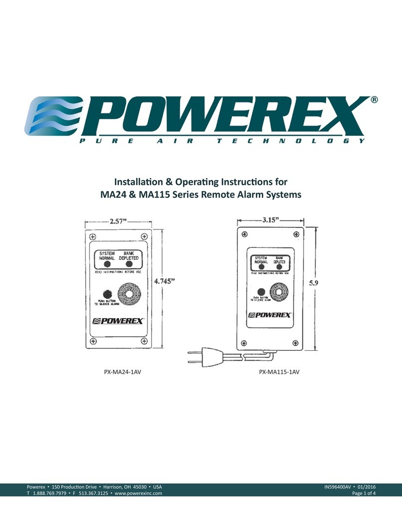
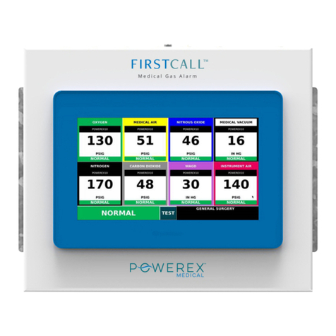
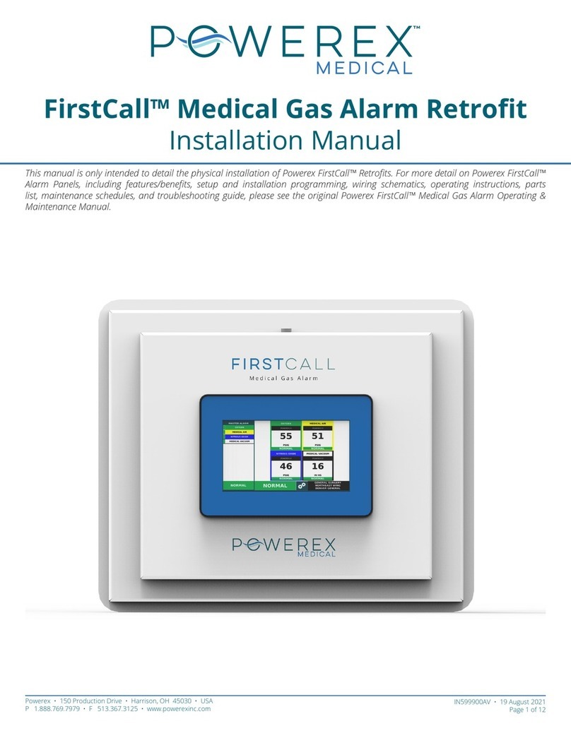
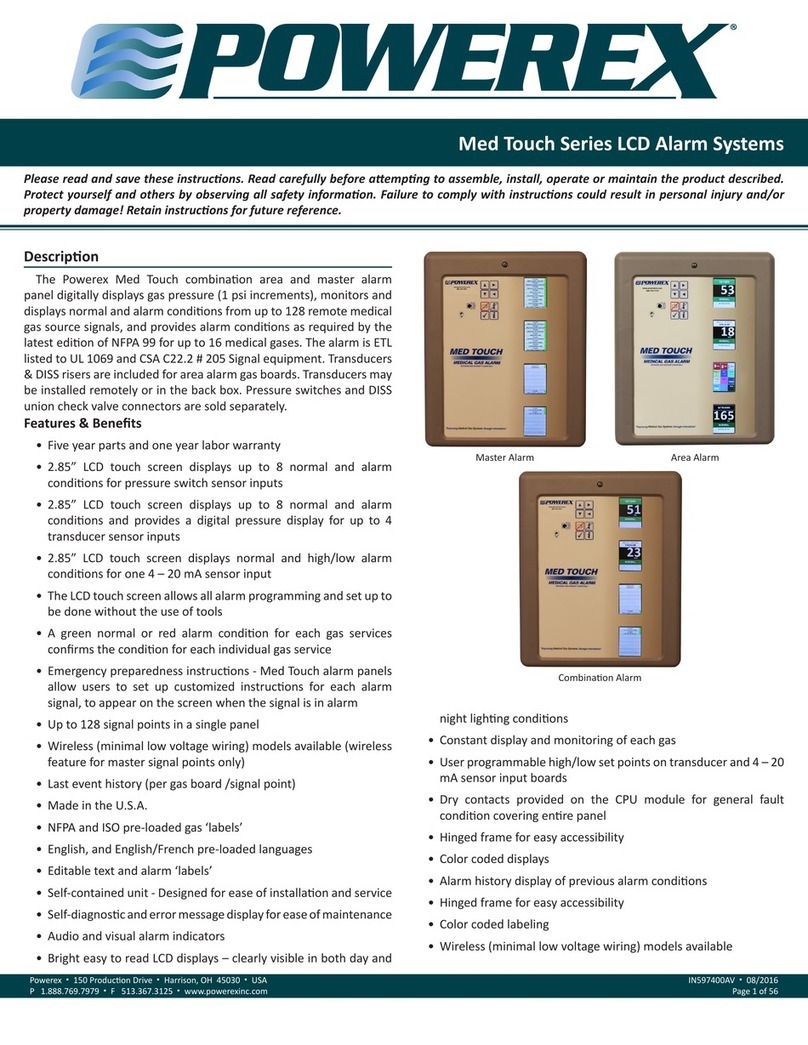
Powerex FirstCall AAP7 Installation and operation manual

FirstCall™ Medical Gas Alarm
Operating & Maintenance Manual
Powerex • 150 Production Drive • Harrison, OH 45030 • USA
P 1.888.769.7979 • F 513.367.3125 • www.powerexinc.com
IN599102AV • 15 September 2020
Page 1 of 36
Please read and save these instructions. Read carefully before attempting to assemble, install, operate or maintain the product
described. Protect yourself and others by observing all safety information. Failure to comply with instructions could result in personal
injury and/or property damage! Retain instructions for future reference.


FirstCall™ Medical Gas Alarm
Operating & Maintenance Manual
Powerex • 150 Production Drive • Harrison, OH 45030 • USA
P 1.888.769.7979 • F 513.367.3125 • www.powerexinc.com
IN599102AV • 15 September 2020
Page 3 of 36
Table of Contents
Responsibilities 4
Introduction 4
Safety Guidelines 4
Product Line Overview 4
Conguration of Models 5
Area Alarm 5
Master Alarm 5
Combo Alarm 5
Installation 6
Unpacking Guide 6
Rough-in Install 6
Wiring for Power 7
Sensor Installation 7
Low Voltage Wiring 8
Front Panel Assembly 8
Wiring Schematics 10
1-4 Gas Area Alarm Panels 10
5-8 Gas Area Alarm Panels 11
23 Digital Input Master Alarm Panel 12
39 Digital Input Master Alarm Panel 13
55 Digital Input Master Alarm Panel 14
23 Digital Inputs and 1-4 Gas
Combo Alarm Panels 15
23 Digital Inputs and 5-6 Gas
Combo Alarm Panels 16
39 Digital Inputs and 1-4 Gas
Combo Alarm Panels 17
39 Digital Inputs and 5-6 Gas
Combo Alarm Panels 18
55 Digital Inputs and 1-4 Gas
Combo Alarm Panels 19
55 Digital Inputs and 5-6 Gas
Combo Alarm Panels 20
Setup and Conguration 21
Login to Settings 21
Keyboard Basics 21
Zone Served Block 21
Gas Badges 21
Settings Menu 22
Basic Settings 22
Alarm Messages 22
Alarm History 22
Alarm Status 22
Alarm Summary 23
Gas Settings 23
Master Alarm Settings 24
Source Gas Description 24
Dry Contact Settings 25
Maintenance Mode 25
Change Password 25
Screen Saver & Brightness Settings 25
Transducer Settings 26
Test & Set High/Low Alarm Points
+/- 20% Current Pressure 26
BACNet Settings 26
Operation 27
TEST Feature 27
Master Alarm Inputs 27
Alarm Event 27
Silencing the Alarm 27
Maintenance 29
Cleaning 29
Battery 29
Maintenance Mode 29
Parts Maintenance List 30
Troubleshooting Guide 31
Specications 32
Appendix A. BACnet Object Names 33
Warranty 35

Powerex • 150 Production Drive • Harrison, OH 45030 • USA
P 1.888.769.7979 • F 513.367.3125 • www.powerexinc.com
IN599102AV • 15 September 2020
Page 4 of 36
FirstCall™ Medical Gas Alarm
Operating & Maintenance Manual
Responsibilities
Information contained in this manual pertains to
the Powerex FirstCall™ medical gas alarm system. The
alarm system will operate as described in this manual
when operated and serviced in compliance with the
instructions.
Installer Responsibilities
The alarm should be handled, installed, and tested
per the recommended practice as described within
this manual. Should any repair or replacement become
necessary, contact Powerex for original equipment or
replacement parts.
User Responsibilities
The alarm should be tested and examined periodically
according to facility codes. Any parts which are found to
be damaged, corroded, contaminated, etc. should be
replaced.
Introduction
Safety Guidelines
Installation of the Powerex FirstCall™ alarm involves
installing the rough-in box, the risers & the transducers
(if it is an area alarm or combination alarm) and front
panel and making the necessary conduit, plumbing
and electrical connections. All installation and testing
should be done in accordance with NFPA 99.
Electrical power intended for the
alarm to be installed should be
disconnected prior to installation. Attention: l’alimentation
électrique a l’intention de faire installer l’alarme devrait
déconnecter avant l’installation.
This device should only be installed
by qualied personnel. Installation
should not be attempted by anyone not having general
experience with the installation of devices of this nature.
Attention: cet appareil ne devrait installer que le personnel
qualié. L’installation ne devrait pas tenter par une personne
n’ayant pas d’expérience générale avec l’installation d’appareils
de cette nature.
Product Line Overview
The Powerex FirstCall™ medical gas alarm systems
monitor the status of medical gases in Category 1
healthcare facilities. The alarm systems are ETL listed to
UL 1069 and comply with the latest edition of NFPA 99.
All alarm systems provide audible and visible indications
of NFPA 99 medical gas alarm conditions.
The FirstCall™ Master Alarm system monitors up to
56 signals indicating the operation and condition of
the source of supply, the reserve source (if any), and
the pressure in the main lines of each medical gas
and vacuum piping system in a Category 1 healthcare
facility.
The FirstCall™ Area Alarm system monitors
the pressure of up to 8 medical gases supplying
anesthetizing locations and other Category 1 spaces.
The FirstCall™ Combination Alarm system monitors
up to 56 source signals (Master) and up to 6 medical
gases (Area) in a single panel.
Powerex FirstCall™ Features and Benets include:
• Designed and manufactured in the USA
• 5 year warranty on parts, 2 year warranty on labor
• 10” high-resolution touchscreen HMI with 7” VE
option available
• Area alarm up to 8 gases
• 4-20mA signal transducers, DISS demand-check
ttings, and gas risers included with Area Alarm
• Transducers are able to be remotely installed up
to 5,000 ft away
• Master alarm 23, 39, and 55 input signals
• Combination alarm up to 6 gases, 23, 39, or 55
input signals
• Ethernet connectivity using BACnet over IP
protocol to building management system -
standard
• Customizable emergency instructions in the event
of an alarm
• Easy to use interface for setup and changing
settings
• Pre-programmed NFPA 99 gas labels and colors
• Event history log accessible at the screen
• Alarm test feature – able to use quickly without
logging in
• Area alarm automatically sets NFPA 99 +/-20%
limits based on current pressure
• Master alarm pre-programmed NFPA 99 source
alarm signals – also customizable

FirstCall™ Medical Gas Alarm
Operating & Maintenance Manual
Powerex • 150 Production Drive • Harrison, OH 45030 • USA
P 1.888.769.7979 • F 513.367.3125 • www.powerexinc.com
IN599102AV • 15 September 2020
Page 5 of 36
• Master alarm signals organized under main
source badge – click through for individual alarm
information
• Push-in terminal blocks to easily connect
transducer and source equipment alarm signals
• Factory set for normally closed signals, able to
change to normally open
• Transducers are gas-specic, and cross-
connecting a transducer with an assigned gas
input will generate an alarm per 2018 NFPA 99
• Hinged frame for easy assembly and maintenance
• Option for digital outputs – contact factory
PLC + HMI
Combination PLC+HMI monitors inputs from medical
gas transducers and alarm points. Input status
displayed on high quality LED HMI touchscreens with
compact built in PLC. Preprogramed standard settings
included with all medical gas inputs. Alarm set points,
alarm messages and descriptions of sources are fully
customizable. Alarm and error history is recorded in
Alarm Summary.
The unit is capable of communicating with building
monitoring system via Ethernet connection using
BACnet over IP.
Screen sizes include 7” and 10”. Both are LED HMI
touchscreens.
7”
10.1”
Conguration of Models
Area Alarm
AAP7-X thru AAP7-XXXXXXXX (7” panel)
AAP10-X thru AAP10-XXXXXXXX (10” panel)
X = gas up to 8
O = Oxygen
A = Medical Air
V = Vacuum
2 = N2O
N = N2
C = CO2
W = WAGD
I = Instrument Air
Example: AAP10-OAV Area Alarm 10” screen Oxygen,
Air, Vacuum
Master Alarm
MAP7-YY
MAP10-YY
YY = digital inputs (23, 39, or 55)
Example: MAP7-23 Master Alarm 7” screen 23 input
signals
Combination Alarm
CAP7-X-YY thru CAP7-XXXXXX-YY (7” panel)
CAP10-X-YY thru CAP10-XXXXXX-YY (10” panel)
X = gas up to 6
O = Oxygen
A = Medical Air
V = Vacuum
2 = N2O
N = N2
C = CO2
W = WAGD
I = Instrument Air
YY = digital inputs (23, 39, or 55)
Example: CAP10-OAV2CW-55 Combo Alarm 10”
screen Oxygen, Air, Vacuum, N2O, CO2, WAGD, 55
input signals

Powerex • 150 Production Drive • Harrison, OH 45030 • USA
P 1.888.769.7979 • F 513.367.3125 • www.powerexinc.com
IN599102AV • 15 September 2020
Page 6 of 36
FirstCall™ Medical Gas Alarm
Operating & Maintenance Manual
Installation
Unpacking Guide
Rough-in box electrical component guide
Rough-in box contains power supply, circuit breaker,
terminal blocks, input expansions and holes for main
line power connection and riser connections.
Cover with PLC+HMI
PLC+HMI is attached to cover and shipped unattached
from the rough-in box. Cover should only be attached
after wall construction is complete.
Riser Guide (Area & Combo Alarm only)
Risers are type L copper tubing with lead free
brass tting. Risers require gas specic DISS tting
with demand valve to be installed prior to installing
transducers. Risers are included standard with all area
and combination alarm panels.
Transducer Guide (Area & Combo Alarm only)
Transducers are unique to each gas. Each transducer
is labeled appropriate gas and has the corresponding
DISS hex nut attached to the sensing end. Transducers
have a solid brass body with ½” NPS threads on cord
end for easy remote installation.
Medical Gas Part Number
Oxygen TDCR-O2
Medical Air TDCR-AIR
Medical Vacuum TDCR-VAC
Nitrous Oxide TDCR-N2O
Nitrogen TDCR-N2
Carbon Dioxide TDCR-CO2
WAGD TDCR-WAGD
Instrument Air TDCR-INST
Rough-in Install
Rough-in box is shipped with dust cover installed.
Dust cover will need to be removed to install the rough-
in box and make electrical connections. The dust
cover should re-installed after the main line electrical
connection is fully connected to protect the electrical
components until the wall covering is complete.
Adjustable depth mounting anges (right & left)
should be utilized to align the front edge of the rough-
in box to be ush with the drywall surface.
Fasten the box to vertical supports (wall studs) so
that the center of the alarm panel is at appropriate use
height. NOTE: Rough-in box should be installed with
open side facing the outside of the wall and the hinge
attachment point at the bottom of the panel.
Reinstall cardboard dust cover.

FirstCall™ Medical Gas Alarm
Operating & Maintenance Manual
Powerex • 150 Production Drive • Harrison, OH 45030 • USA
P 1.888.769.7979 • F 513.367.3125 • www.powerexinc.com
IN599102AV • 15 September 2020
Page 7 of 36
Wiring for Power
For personal safety, lock out and tag
out the associated circuit breaker
disconnect for the source of 120V AC power. Attention:
Pour votre sécurité personnelle, verrouillez et étiquetez le
sectionneur du disjoncteur associé pour la source
d’alimentation de 120 V CA.
For personal safety and to avoid
damage to the alarm, ensure that the
circuit breaker is in the OFF position. Attention: Pour
votre sécurité personnelle et pour éviter d’endommager
l’alarme, assurez-vous que le disjoncteur est en position
OFF.
Route incoming mains power through the knock-out
at the bottom of the rough-in box with a UL recognized
cable with a minimum gauge of 18 AWG and rated for
100-240V AC, 50/60Hz, 2A, single phase power.
All Models of Powerex FirstCall alarm Panels must be
powered by the life safety branch or critical branch of
the essential electrical system as required in NFPA 99.
Ground wire – Strip ½” of insulation and connect the
ground wire to the appropriate terminal block (GND).
Neutral wire – Strip ½” of insulation and connect the
neutral lead to the appropriate terminal block (N).
Hot wire – Strip the insulation and connect the hot
lead to the appropriate terminal block (120V AC).
Sensor Installation (Area & Combo Alarms Only)
Local Installation
Locate copper risers packaged inside the alarm
rough-in box.
Install the risers into the top of the rough-in box
through the holes provided using NPS threads on brass
tting and washer. NOTE: All access holes in the rough-
in box are plugged with plastic snap in caps.
Braze copper tubes to appropriate building plumbing
using appropriate NFPA 99 procedures. Install the gas
specic DISS demand valve into the appropriate riser.
Pipeline Remote Installation
Sensors may be installed directly onto hospital
pipeline by placing transducer in junction box and
attaching appropriate gas.
ZVB Remote Installation
Sensors may be installed remotely in Powerex zone
valve boxes using appropriate Powerex zone valve box
sensing kit.
Part Number Description
SENSE-O2 Oxygen Sensing Kit
SENSE-AIR Medical Air Sensing Kit
SENSE-VAC Medical Vacuum Sensing Kit
SENSE-N2O Nitrous Oxide Sensing Kit
SENSE-N2 Nitrogen Sensing Kit
SENSE-CO2 Carbon Dioxide Sensing Kit
SENSE-WAGD WAGD Sensing Kit
SENSE-INST Instrument Air Sensing Kit
Remove the plug from the top port on the appropriate
valve in the zone valve box. Install ⅛” to ¼” reducer
elbow into the port.
Install the ¼” to DISS adapter with demand valve into
the reducer elbow.
Attach the transducer to the DISS tting.

Powerex • 150 Production Drive • Harrison, OH 45030 • USA
P 1.888.769.7979 • F 513.367.3125 • www.powerexinc.com
IN599102AV • 15 September 2020
Page 8 of 36
FirstCall™ Medical Gas Alarm
Operating & Maintenance Manual
Low Voltage Wiring
Wire Type and Size
All low voltage wiring must meet the following
requirements:
• Stranded wire no smaller than 22 AWG, conductor
insulation at least .010in.
• Circuit length not to exceed the following lengths
for the indicated wiring gauges:
• Up to 5000 feet: 18 AWG
• Up to 3200 feet: 20 AWG
• Up to 2000 feet: 22 AWG
• Cable must be twisted pair shielded type. Multi-
pair cables within one common shield are
acceptable.
Sensor wiring (Area & Combo Alarm only)
For personal safety, lock out and tag
out the associated circuit breaker
disconnect for the source of 120V AC power. Attention:
Pour votre sécurité personnelle, verrouillez et étiquetez le
sectionneur du disjoncteur associé pour la source
d’alimentation de 120 V CA.
For personal safety and to avoid
damage to the alarm, ensure that the
circuit breaker is in the OFF position. Attention: Pour
votre sécurité personnelle et pour éviter d’endommager
l’alarme, assurez-vous que le disjoncteur est en position
OFF.
Install the sensor wires into the appropriate terminal
block. There are enough terminal blocks for up to 8
gases. Install the sensors in the order they are to be
displayed on the screen.
The terminal blocks are push-in style with a release
button. A small at-head screwdriver (or similar tool)
should be used to depress the release button to make
wire insertion easier.
It is important that the sensors are wired to the
correct terminal block. Per NFPA 99, an alarm will sound
for cross-connected sensors.
Source alarm signal wiring (Master & Combo Alarm
only)
Install the input wires from the source equipment
into the appropriate terminal blocks.
Front Panel Assembly
Front cover assembly with HMI+PLC combination
screen is shipped unattached to the rough-in box
assembly. Front cover is attached using hinge on lower
inside ange of rough-in box.
Remove dust cover from rough-in box and discard.
Attach front cover by placing threaded studs on lower
ange of cover through the provided hinge holes. Place
provided hex nuts over studs and tighten.

FirstCall™ Medical Gas Alarm
Operating & Maintenance Manual
Powerex • 150 Production Drive • Harrison, OH 45030 • USA
P 1.888.769.7979 • F 513.367.3125 • www.powerexinc.com
IN599102AV • 15 September 2020
Page 9 of 36
Plug power cord from power supply into power slot
on PLC.
(For panels with 39+ digital inputs and/or 5+ gas
inputs) Plug I/O module expansion adapter cord into
appropriate port.
Place unattached side of panel lanyards over provided
threaded studs on the left side of the cover assembly.
Place provided washer and hex nut over the stud and
tighten the hex nuts.
Plug wired connectors from terminal blocks into
appropriate input blocks in PLC.

Powerex • 150 Production Drive • Harrison, OH 45030 • USA
P 1.888.769.7979 • F 513.367.3125 • www.powerexinc.com
IN599102AV • 15 September 2020
Page 10 of 36
FirstCall™ Medical Gas Alarm
Operating & Maintenance Manual
Area Alarm Panel Wiring Schematic
1-4 Gas Area Alarm Panels – AP000A004AJ
BLACK (4X)
TRANS.
1
RED
BLACK
TRANS.
2
TRANS.
3
TRANS.
4
RED
BLACK
RED
BLACK
RED
BLACK
Note:Transducers and transducer wiring are field installed
GAS
4 -
GAS
3 -
GND
⏚
120
LINE
V AC
NRES RES GF GAS
1 -
GAS
2 -
COM2
16
I9
17
I10
18
I11
19
I12
20
I13
21
I14
22
I15
23
I16
24
I17
25
I18
26
I19
27
I20
28
I21
29
I22
30
15
IN
AI3
14
IN
AI2
13
COM
1
12
AI1
11
AI0
10
IN
8
9
IN
7
8
IN
6
7
IN
5
6
IN
4
5
IN
3
4
IN
2
3
IN
1
2
IN
0
1
COM
0
Legend
A3
A2
A1
A0
YELLOW
BLUE
BLUE
151413121110987654321
OUT
6
COM
4
OUT
0
COM
3
WHITE
BLUE-WHITE
-+
HORN
GREEN
PLC/HMI
OUTPUT BAR
PLC/HMI
INPUT BAR 2 (GRAY)
BROWN (4X)
BLUE-WHITE
PLC/HMI
BLUE
GREEN
BLUE-W
0V
+V
PLC/HMI
INPUT BAR 1 (BLACK)
FOR BUILDING MAIN POWER TIE IN
GND LINE N
BLACK
RES RES
CB
L
24V
DC
-
+
RED
N
POWER
SUPPLY
120V AC
24V DC
xx WATTS
BLUE-WHITE
BLUE
BLUE-WHITE
All Models of Powerex FirstCall alarm panels must be powered by the life safety branch or critical branch
of the essential electrical system as required in NFPA 99.
BLUE BLUE

FirstCall™ Medical Gas Alarm
Operating & Maintenance Manual
Powerex • 150 Production Drive • Harrison, OH 45030 • USA
P 1.888.769.7979 • F 513.367.3125 • www.powerexinc.com
IN599102AV • 15 September 2020
Page 11 of 36
Area Alarm Panel Wiring Schematic
5-8 Gas Area Alarm Panels – AP000A008AJ

Powerex • 150 Production Drive • Harrison, OH 45030 • USA
P 1.888.769.7979 • F 513.367.3125 • www.powerexinc.com
IN599102AV • 15 September 2020
Page 12 of 36
FirstCall™ Medical Gas Alarm
Operating & Maintenance Manual
Master Alarm Panel Wiring Schematic
23 Digital Input Master Alarm Panel – AP000M230AJ

FirstCall™ Medical Gas Alarm
Operating & Maintenance Manual
Powerex • 150 Production Drive • Harrison, OH 45030 • USA
P 1.888.769.7979 • F 513.367.3125 • www.powerexinc.com
IN599102AV • 15 September 2020
Page 13 of 36
Master Alarm Panel Wiring Schematic
39 Digital Input Master Alarm Panel – AP000M390AJ

Powerex • 150 Production Drive • Harrison, OH 45030 • USA
P 1.888.769.7979 • F 513.367.3125 • www.powerexinc.com
IN599102AV • 15 September 2020
Page 14 of 36
FirstCall™ Medical Gas Alarm
Operating & Maintenance Manual
Master Alarm Panel Wiring Schematic
55 Digital Input Master Alarm Panel – AP000M550AJ

FirstCall™ Medical Gas Alarm
Operating & Maintenance Manual
Powerex • 150 Production Drive • Harrison, OH 45030 • USA
P 1.888.769.7979 • F 513.367.3125 • www.powerexinc.com
IN599102AV • 15 September 2020
Page 15 of 36
Combo Alarm Panel Wiring Schematic
23 Digital Inputs and 1-4 Gas Combo Alarm Panels – AP000C234AJ
TRANS.
1
RED
BLACK
TRANS.
2
TRANS.
3
TRANS.
4
RED
BLACK
RED
BLACK
RED
BLACK
RED (4X)
Note:Transducers and transducer wiring is field installed
BLACK (4X)
BLUE-WHITE
BLUE
BLUE
BLUE
BLUE
WHITE
CB
N
L
24V
DC
-
+
POWER
SUPPLY
120V AC
24V DC
xx WATTS
BLACK
RED
FOR BUILDING MAIN POWER TIE IN
GND LINE N
I22 I21 I20 I19 I18 I17 I16 I15 I14 I13 I12 I11 I10 I9 I8 I7 I6 I5 I4 I3 I2 I1I0
YELLOW
BLUE
BLUE
A3
A2
A1
A0
151413121110987654321
OUT
6
COM
4
OUT
0
COM
3
BLUE-WHITE
BLUE-W, BLUE (14X)
-+
HORN
BLUE-W (2X), BLUE (9X), BROWN (4X)
BLUE (14X)
BLUE (9X)
BROWN (4X)
PLC/HMI
OUTPUT BAR
BLUE-WHITE
BLUE (14X)
BLUE (9X)
BLUE-W
BLUE-WHITE
PLC/HMI
INPUT BAR 2 (GRAY)
BROWN (4X)
BLUE-W (2X)
PLC/HMI
BLUE
GREEN
BLUE-WHITE 0V
+V
PLC/HMI
INPUT BAR 1 (BLACK)
123456789101112131415
AI0
AI1 COM
0
IN
0
IN
1
IN
2
IN
3
IN
4
IN
5
IN
6
IN
7
IN
8
COM
1
IN
AI2
IN
AI3
30 29 28 27 26 25 24 23 22 21 20 19 18 17 16
I22 I21 I20 I19 I18 I17 I16 I15 I14 I13 I12 I11 I10 I9 COM2
All Models of Powerex FirstCall alarm panels must be powered by the life safety branch or
critical branch of the essential electrical system as required in NFPA 99

Powerex • 150 Production Drive • Harrison, OH 45030 • USA
P 1.888.769.7979 • F 513.367.3125 • www.powerexinc.com
IN599102AV • 15 September 2020
Page 16 of 36
FirstCall™ Medical Gas Alarm
Operating & Maintenance Manual
Combo Alarm Panel Wiring Schematic
23 Digital Inputs and 5-6 Gas Combo Alarm Panels – AP000C236AJ
TRANS.
1
RED
BLACK
TRANS.
2
TRANS.
3
TRANS.
4
RED
BLACK
RED
BLACK
RED
BLACK
RED (4X)
Note:Transducers and transducer wiring is field installed
BLACK (4X)
All Models of Powerex FirstCall alarm panels must be powered by the life safety branch or
critical branch of the essential electrical system as required in NFPA 99
BLUE-WHITE (2X)
BLUE-WHITE
PLC/HMI
OUTPUT BAR
BROWN (4X)
BLUE (9X)
BLUE (14X)
BLUE-W (2X), BLUE (9X), BROWN (4X)
HORN +
-
BLUE-W, BLUE (14X)
BLUE-WHITE
COM
3
OUT
0
COM
4
OUT
6
1 2 3 4 5 6 7 8 9 10 11 12 13 14 15
A0 A1 A2 A3
BLUE
BLUE
YELLOW
I0
I1
I2
I3
I4
I5
I6
I7
I8
I9
I10
I11I12
I13
I14
I15I16
I17
I18I19
I20
I21
I22
FOR BUILDING MAIN POWER TIE IN
GND LINE N
I1I
I0I
BLUE-W (2X)
RED
BLACK
POWER
SUPPLY
120V AC
24V DC
xx WATTS
+-
24V
DC
LN
CB
WHITE
BLUE BLUE
BLUE
BLUE
BLUE BLUE-WHITE
BLUE-WHITE
PLC/HMI
INPUT BAR 1 (BLACK)
+V
0V
BLUE-WHITE
GREEN
BLUE
PLC/HMI
BLUE-W (2X)
BROWN (4X)
PLC/HMI
INPUT BAR 2 (GRAY)
BLUE-WHITE
BLUE-W
BLUE (9X)
BLUE (14X)
BLUE
GREEN
BLUE-WHITE
15
IN
AI3
14
IN
AI2
13
COM
1
12
AI1
11
AI0
10
IN
8
9
IN
7
8
IN
6
7
IN
5
6
IN
4
5
IN
3
4
IN
2
3
IN
1
2
IN
0
1
COM
0
COM2
16
I9
17
I10
18
I11
19
I12
20
I13
21
I14
22
I15
23
I16
24
I17
25
I18
26
I19
27
I20
28
I21
29
I22
30
Transd. 6Transd. 5
141312
I3I
11
CM
3
10
9
I2I
8
CM
2
765
I1I
4
CM
1
32
I0I
1
CM
0
Transd. 6Transd. 5
141312
I3I
11
CM
3
10
9
I2I
8
CM
2
765
I1I
4
CM
1
32
I0I
1
CM
0
O+

FirstCall™ Medical Gas Alarm
Operating & Maintenance Manual
Powerex • 150 Production Drive • Harrison, OH 45030 • USA
P 1.888.769.7979 • F 513.367.3125 • www.powerexinc.com
IN599102AV • 15 September 2020
Page 17 of 36
Combo Alarm Panel Wiring Schematic
39 Digital Inputs and 1-4 Gas Combo Alarm Panels – AP000C394AJ
CONFIDENTIAL DISCLO SURE
This drawing is the property of POWEREX
of the SCOTT FETZER
COMPANY and is subject to return on demand.
Its contents are confidential and must not be
copied or submitted to
outside parties for use or examination.
SHEET 1 OF 1
ORIGINATION DATE
APPROVALS ON FILE IN PLM
DESCRIPTION
150 PRODUCTION DRIVE, HARRISON OH 45030
(888) 769-7979
DRAWING NUMBER
REVISION
D
SIZE
8/13/2020
COMBO ALARM PANEL 24v Horn
AP000C
A
REVISION NOTES
DESCRIPTION
ECN PR/NOR
PRODUCTION RELEASE PXEC0342 XXXXXXXX
AUTHOR
JAbt
OPTIONAL
TRANS.
1
RED
BLACK
TRANS.
2
TRANS.
3
TRANS.
4
RED
BLACK
RED
BLACK
RED
BLACK
RED (4X)
Note:Transducers and transducer wiring is field installed
BLACK (4X)
RES
RES
GND
⏚
NGAS
4 -
GAS
3 -
RES RES GF IN
22
IN
21
IN
20
IN
19
IN
18
IN
17
IN
16
IN
15
IN
14
IN
13
IN
12
IN
11
IN
10
IN
9
IN
8
IN
7
IN
6
IN
5
IN
4
IN
3
IN
2
IN
1
IN
0
GAS
1 -
GAS
2 -
Legend Lower terminal
set
120
LINE
V AC
IN
38
IN
37
IN
36
IN
35
IN
34
IN
33
IN
32
IN
31
IN
30
IN
29
IN
28
IN
27
IN
26
IN
25
IN
24
IN
23
1-4 GAS, 39 INPUT
BLUE-WHITE
BLUE-WHITE
BLUE-WHITE
BLUE
BLUE
BLUE
BLUE
BLUE
BLUE
WHITE
CB
N
L
24V
DC
-
+
POWER
SUPPLY
120V AC
24V DC
xx WATTS
BLACK
RED
FOR BUILDING MAIN POWER TIE IN
GND LINE N
I22 I21 I20 I19 I18 I17 I16 I15 I14 I13 I12 I11 I10 I9 I8 I7 I6 I5 I4 I3 I2 I
1
I
0
YELLOW
BLUE
BLUE
A3
A2
A1
A0
151413121110987654321
OUT
6
COM
4
OUT
0
COM
3
BLUE-WHITE
BLUE
BLUE-W, BLUE (14X)
-+
HORN
BLUE-W (2X), BLUE (9X), BROWN (4X)
BLUE (14X)
BLUE (9X)
BROWN (4X)
PLC/HMI
OUTPUT BAR
BLUE-WHITE
BLUE-WHITE ( 4X)
(GROUP 1)
(GROUP 2)
BLUE (14X)
BLUE (9X)
BLUE-W
BLUE-WHITE
PLC/HMI
INPUT BAR 2 (GRAY)
BROWN (4X)
BLUE-W (2X)
PLC/HMI
BLUE
GREEN
BLUE-WHITE 0V
+V
PLC/HMI
INPUT BAR 1 (BLACK)
I38 I37 I36 I35 I34 I33 I32 I31 I30 I29 I28 I27 I26 I25 I24 I23
BLUE
GREEN
BLUE-WHITE
O+
BLUE (8X) (GROUP 2)
I38
I37
I36
I35
I34
I33
I32
I31
BLUE (8X) (GROUP 1)
123456789101112131415
AI0
AI1 COM
0
IN
0
IN
1
IN
2
IN
3
IN
4
IN
5
IN
6
IN
7
IN
8
COM
1
IN
AI2
IN
AI3
30 29 28 27 26 25 24 23 22 21 20 19 18 17 16
I22 I21 I20 I19 I18 I17 I16 I15 I14 I13 I12 I11 I10 I9 COM2
1234567891011
I30
I29I28
I27I26I25I24
I23
12 13 14 15 16 17 18 19 20 21 22
All Models of Powerex FirstCall alarm panels must be powered by the life safety branch or
critical branch of the essential electrical system
as required in NFPA 99

Powerex • 150 Production Drive • Harrison, OH 45030 • USA
P 1.888.769.7979 • F 513.367.3125 • www.powerexinc.com
IN599102AV • 15 September 2020
Page 18 of 36
FirstCall™ Medical Gas Alarm
Operating & Maintenance Manual
Combo Alarm Panel Wiring Schematic
39 Digital Inputs and 5-6 Gas Combo Alarm Panels – AP000C396AJ
REVISION NOTES
DESCRIPTION
PRODUCTION RELEASE
TRANS.
1
RED
BLACK
TRANS.
2
TRANS.
3
TRANS.
4
TRANS.
5
TRANS.
6
RED
BLACK
RED
BLACK
RED
BLACK
RED
BLACK
RED
BLACK
RED (6X)
Note:Transducers and transducer wiring is field installed
BLACK (6X)
I23
I24
I25
I26
I27I28
I29I30
I31
I32
I33I3 4
I35
I36I37
I38
BLUE-WHITE
BLUE-WHITE
BLUE-WHITE
BLUE-WHITE
BLUE
BLUE
BLUE
BLUE
BLUE
WHITE
CB
NL
24V
DC
-
+
POWER
SUPPLY
120V AC
24V DC
xx WATTS
BLACK
RED
BLUE-W (2X)
I0I I1I
FOR BUILDING MAIN POWER TIE IN
GND LINE N
I22 I21 I2 0 I19 I18 I17 I16 I15 I14 I1 3 I12 I11 I10 I9 I8 I7 I6 I5 I4 I3 I2 I1I0
YELLO W
BLUE
BLUE
A3
A2
A1
A0
151413121110987654321
OUT
6
COM
4
OUT
0
COM
3
BLUE-WHITE
BLUE
BLUE-W, BLUE (14X)
-+
HORN
BLUE-W (2X), BLUE (9X), BROWN (4X)
BLUE (14X)
BLUE (9X)
BROWN (4X)
PLC/HMI
OUTPUT BAR
BLUE-WHITE
BLUE-WHITE ( 2X)
30
I22
29
I21
28
I20
27
I19
26
I18
25
I17
24
I16
23
I15
22
I14
21
I13
20
I12
19
I11
18
I10
17
I9
16
COM 2
COM
0
1
IN
0
2
IN
1
3
IN
2
4
IN
3
5
IN
4
6
IN
5
7
IN
6
8
IN
7
9
IN
8
10
AI0
11
AI1
12
COM
1
13
IN
AI2
14
IN
AI3
15
GROUP 2
GROUP 1
(GROUP 1)
(GROUP 2)
1
CM
0
2
I0I
3 4
CM
1
5
I1I
6 7
8
CM
2
9
I2I
10 11
CM
3
12
I3I
13 14
BLUE-WHITE (2X)
1
CM
0
2
I0I
3 4
CM
1
5
I1I
6 7
8
CM
2
9
I2I
10 11
CM
3
12
I3I
13 14
Transd. 5 Transd. 6
BLUE (14X)
BLUE (9X)
BLUE-W
BLUE-WHITE
PLC/HMI
INPUT BAR 2 (GRAY)
BROWN (4X)
BLUE-W (2X)
PLC/HMI
BLUE
GREEN
BLUE-WHITE 0V
+V
PLC/HMI
INPUT BAR 1 (BLACK)
BLUE
GREEN
BLUE-WHITE
O+
1234567
12 13 14 15 16 17 18
8 9 10 11
19 20 21 22
BLUE (8X) (GROUP 2)
I38
I37
I36
I35I34I33
I32I31
I30
I29I28
I27I26I25I24
I23
BLUE (8X) (GROUP 1)
All Models of Powerex FirstCall alarm panels must be powered by the life safety branch or
critical branch of the essential electrical system as required in NFPA 99

FirstCall™ Medical Gas Alarm
Operating & Maintenance Manual
Powerex • 150 Production Drive • Harrison, OH 45030 • USA
P 1.888.769.7979 • F 513.367.3125 • www.powerexinc.com
IN599102AV • 15 September 2020
Page 19 of 36
REVISION NOTES
DESCRIPTION
PRODUCTION RELEASE
TRANS.
1
RED
BLACK
TRANS.
2
TRANS.
3
TRANS.
4
RED
BLACK
RED
BLACK
RED
BLACK
RED (4X)
Note:Transducers and transducer wiring is field installed
BLACK (4X)
BLUE-WHITE
PLC/HMI
OUTPUT BAR
BROWN (4X)
BLUE (9X)
BLUE (14X)
BLUE-W (2X), BLUE (9X), BROWN (4X)
HORN +
-
BLUE-W, BLUE (14X)
BLUE
BLUE-WHITE
COM
3
OUT
0
COM
4
OUT
6
12345678910 11 12 13 14 15
A0 A1 A2 A3
BLUE
BLUE
YELLO W
I0
I1
I2
I3
I4
I5
I6
I7
I8I9
I10
I11I12
I13
I14
I15I16
I17
I18
I19I20I21
I22
FOR BUILDING MAIN POWER TIE IN
GND LINE N
RED
BLACK
POWER
SUPPLY
120V AC
24V DC
xx WATTS
+-
24V
DC
LN
CB
WHITE
BLUE BLUE
BLUE
BLUE
BLUE
BLUE BLUE-WHITE
BLUE-WHITE
PLC/HMI
INPUT BAR 1 (BLACK)
+V
0V
BLUE-WHITE
GREEN
BLUE
PLC/HMI
BLUE-W (2X)
BROWN (4X)
PLC/HMI
INPUT BAR 2 (GRAY)
BLUE-WHITE
BLUE-W
BLUE (9X)
BLUE (14X)
1234567
12 13 14 15 16 17 18
8910 11
19 20 21 22
1234567
12 13 14 15 16 17 18
8 9 10 11
19 20 21 22
BLUE (8X) (GROUP 2)
I38
I37
I36
I35I34I33
I32I31
I30
I29I28
I27I26I25I24
I23
BLUE (8X) (GROUP 1)
(GROUP 2)
(GROUP 1)
GROUP 1
GROUP 2
BLUE
GREEN
BLUE-WHITE
O+
15
IN
AI3
14
IN
AI2
13
COM
1
12
AI1
11
AI0
10
IN
8
9
IN
7
8
IN
6
7
IN
5
6
IN
4
5
IN
3
4
IN
2
3
IN
1
2
IN
0
1
COM
0
COM2
16
I9
17
I10
18
I11
19
I12
20
I13
21
I14
22
I15
23
I16
24
I17
25
I18
26
I19
27
I20
28
I21
29
I22
30
(GROUP 4)
BLUE (8X) (GROUP 4)
BLUE-WHITE ( 4X)
BLUE (8X) (GROUP 3)
(GROUP 3)
I44 I43 I42 I41 I40 I39
I38 I37 I36 I35 I34 I33 I32 I31
I30 I29 I28 I27 I26 I25 I24 I23I54 I53 I52 I51 I50 I49 I48 I47
I46 I45
BLUE-WHITE (3X)
I39 I40 I41 I42 I43 I44 I45 I46
I47 I48 I49 I50 I51 I52 I53 I54
BLUE-WHITE
All Models of Powerex FirstCall alarm panels must be powered by the life safety branch or
critical branch of the essential electrical system as required in NFPA 99
Combo Alarm Panel Wiring Schematic
55 Digital Inputs and 1-4 Gas Combo Alarm Panels – AP000C554AJ

Powerex • 150 Production Drive • Harrison, OH 45030 • USA
P 1.888.769.7979 • F 513.367.3125 • www.powerexinc.com
IN599102AV • 15 September 2020
Page 20 of 36
FirstCall™ Medical Gas Alarm
Operating & Maintenance Manual
BLUE-WHITE
DESCRIPTION
PRODUCTION RELEASE
TRANS.
1
RED
BLACK
TRANS.
2
TRANS.
3
TRANS.
4
TRANS.
5
TRANS.
6
RED
BLACK
RED
BLACK
RED
BLACK
RED
BLACK
RED
BLACK
RED (6X)
Note:Transducers and transducer wiring is field installed
BLACK (6X)
PLC/HMI
INPUT BAR 1 (BLACK)
+V
0V
BLUE-WHITE
GREEN
BLUE
PLC/HMI
BLUE-W (2X)
BROWN (4X)
PLC/HMI
INPUT BAR 2 (GRAY)
BLUE-WHITE
BLUE-W
BLUE (9X)
BLUE (14X)
PLC/HMI
OUTPUT BAR
BROWN (4X)
BLUE (9X)
BLUE (14X)
BLUE-W (2X), BLUE (9X), BROWN (4X)
HORN +
-
BLUE-W, BLUE (14X)
BLUE
BLUE-WHITE
COM
3
OUT
0
COM
4
OUT
6
12345678910 11 12 13 14 15
A0 A1 A2 A3
BLUE
BLUE
YELLOW
I0
I1
I2
I3
I4
I5
I6
I7
I8I9
I10
I11I12I13
I14
I15I16
I17
I18
I19I20I2 1
I22
FOR BUILDING MAIN POWER TIE IN
GND LINE N
1234567
12 13 14 15 16 17 18
8910 11
19 20 21 22
1 2 3 4 5 6 7
12 13 14 15 16 17 18
8 9 10 11
19 20 21 22
Transd. 6Transd. 5
141312
I3I
11
CM
3
10
9
I2I
8
CM
2
765
I1I
4
CM
1
32
I0I
1
CM
0
I1I
I0I
BLUE-W (2X) BLUE-WHITE (2X)
Transd. 6Transd. 5
141312
I3I
11
CM
3
10
9
I2I
8
CM
2
765
I1I
4
CM
1
32
I0I
1
CM
0
BLUE (8X) (GROUP 2)
I38
I37
I36
I35I3 4I33
I32I31
I30
I29I28
I27I26I25I24
I23
BLUE (8X) (GROUP 1)
(GROUP 2)
(GROUP 1)
GROUP 1
GROUP 2
BLUE
GREEN
BLUE-WHITE
O+
15
IN
AI3
14
IN
AI2
13
COM
1
12
AI1
11
AI0
10
IN
8
9
IN
7
8
IN
6
7
IN
5
6
IN
4
5
IN
3
4
IN
2
3
IN
1
2
IN
0
1
COM
0
COM 2
16
I9
17
I10
18
I11
19
I12
20
I13
21
I14
22
I15
23
I16
24
I17
25
I18
26
I19
27
I20
28
I21
29
I22
30
(GROUP 4)
BLUE (8X) (GROUP 4)
BLUE-WHITE ( 4X)
BLUE (8X) (GROUP 3)
(GROUP 3)
I44 I43 I4 2 I41 I4 0 I39
I38 I37 I3 6 I35 I3 4 I33 I32 I31
I30 I29 I2 8 I27 I2 6 I25 I24 I2 3I5 4 I53 I52 I5 1 I50 I49 I48 I47
I46 I45
BLUE-WHITE (3X)
I39 I4 0 I41 I4 2 I43 I44 I45 I46
I47 I4 8 I49 I50 I51 I52 I5 3 I54
RED
BLACK
POWER
SUPPLY
120V AC
24V DC
xx WATTS
+-
24V
DC
LN
CB
WHITE
BLUE
BLUE
BLUE
BLUE
BLUE
BLUE-WHITE
BLUE-WHITE
BLUE-WHITE
BLUE-WHITE
All Models of Powerex FirstCall alarm panels must be powered by the life safety branch or
critical branch of the essential electrical system as required in NFPA 99
Combo Alarm Panel Wiring Schematic
55 Digital Inputs and 5-6 Gas Combo Alarm Panels – AP000C556AJ
This manual suits for next models
11
Table of contents
Other Powerex Security System manuals
Popular Security System manuals by other brands

Htzsafe
Htzsafe 805A user manual

Honeywell
Honeywell MA-2000 installation manual

ADEMCO
ADEMCO VISTA user manual

Aritech
Aritech Attender 50 owner's manual

Strategic Vista
Strategic Vista SG17TQ5580UQ Series instruction manual

Precision Digital Corporation
Precision Digital Corporation Vigilante II PD154 instruction manual