manuals.online logo
Brands
  1. Home
  2. •
  3. Brands
  4. •
  5. Powerex
  6. •
  7. Security System
  8. •
  9. Powerex MA24 Series Manual

Powerex MA24 Series Manual

Installaon & Operang Instrucons for
MA24 & MA115 Series Remote Alarm Systems
Powerex • 150 Producon Drive • Harrison, OH 45030 •USA
T 1.888.769.7979 • F 513.367.3125 • www.powerexinc.com
IN596400AV • 01/2016
Page 1 of 4
PX-MA24-1AV PX-MA115-1AV
Installaon & Operang Instrucons for
MA24 & MA115 Series Remote Alarm Systems
Powerex • 150 Producon Drive • Harrison, OH 45030 •USA
T 1.888.769.7979 • F 513.367.3125 • www.powerexinc.com
IN596400AV • 01/2016
Page 2 of 4
Introducon
Powerex remote alarms are designed to aach to Powerex
manifold systems or to pressure switches. They signal an alarm
condion is present.
A typical alarm setup signals when pressure in the supply
cylinders of a manifold goes below a set point, indicang the
cylinders need replacing.
All of the Powerex Remote Alarm models acvate when the
control circuit opens. The open circuit signals an alarm condion.
A closed circuit indicates a system normal condion.
Powerex manufactures the six remote alarm models shown
below.
PX-MA24-1V PX-MA115-1V
PX-MA24-1AV PX-MA115-1AV
PX-MA24-2AV PX-MA115-2AV
Model Descripons
The PX-MA24 models require a 24 VAC power source. These
models are designed to aach to a Powerex automac or
semiautomac switchover manifold. The 24 VAC power comes
from the power supply provided with the manifold control box
(Part # PX-1118-0100). The power supply box also contains dry
contacts which are acvated by pressure switches inside the
manifold control box. When these dry contacts are connected to
the Powerex PX-MA24 remote alarm, the alarm gives a visual or
audio/visual indicaon of a low supply gas condion.
The PX-MA115 models are designed to connect to 115 VAC.
These units have an internal transformer and an external six (6)
foot power cord that terminates in a stan dard two-prong 115
VAC plug. These units are designed to aach to any pressure
switch(es) on any manifold system to signal an alarm condion.
The 115 VAC models all ulize 12 VAC internal power to sense the
open or closed condion across the pressure switch.
The PX-MA24-1V and PX-MA115-1V models (Figures 1 and 2)
have provisions for connec on to a single manifold or pressure
switch. The 1V models have a single set of lights to indicate
the low pressure condion. The set of lights consist of a green
“System Normal” and a red “Bank Depleted” light. The “System
Normal” light is acvated as long as the manifold or pressure
switch circuit is in a closed condion and power is supplied to
the alarm box. When the alarm circuit opens, the green “’System
Normal” light goes out and the red “Bank Depleted” light goes
on.
The PX-MA24-1AV and PX-MA115-1AV models (Figures 3 and 4)
have provisions for con necon to a single manifold or pressure
switch. The 1AV models have a single set of lights and a buzzer
that sounds to signal that an alarm condion is present. The
single set of lights consists of a green “System Normal” and a red
“Bank Depleted” light There is a squelch buon on the front of
the 1AV panel. Pushing the squelch buon stops the buzzer. The
buzzer automacally resets when the normal condion resumes.
The PX-MA24-2AV and PX-MA115-2AV models (Figures 5 and 6)
have provisions to aach to two manifolds or pressure switches.
The 2AV models have two sets of lights, each set aached to a
dierent manifold sensor. Each set of lights consists of a green
“System Normal” and a red “Bank Depleted” light.
The 2AV models also have one buzzer which sounds when either
bank reaches an alarm condion. Like the 1AV models, the 2AV
has a squelch buon that silences the buzzer when pushed. The
buzzer automacally resets when the normal condion resumes.
Figure 1: PX-MA24-1V Figure 2: PX-MA115-1V
Figure 3: PX-MA24-1AV Figure 4: PX-MA115-1AV
Figure 5: PX-MA24-2AV Figure 6: PX-MA115-2AV
Installaon & Operang Instrucons for
MA24 & MA115 Series Remote Alarm Systems
Powerex • 150 Producon Drive • Harrison, OH 45030 •USA
T 1.888.769.7979 • F 513.367.3125 • www.powerexinc.com
IN596400AV • 01/2016
Page 3 of 4
Installaon
1. Remove the four (4) phillips head screws from the four
corners of the front of the alarm box. Remove the cover.
2. Remove the circuit board from the alarm box.
3. Mount the alarm box to the desired surface, ulizing the
holes in the back surface of the box. Powerex alarm boxes
are not waterproof. Mount in a locaon protected from the
elements.
4. Aer the box is mounted to the mounng surface, use the
½” conduit bushing to aach conduit through the holes
provided.
5. Connect the wiring to the connectors on the top back of the
circuit board as directed by Figures 7, 8, 9, and.
6. Install the circuit board into the alarm box. Reinstall the
cover onto the alarm box.
7. Apply power to the unit.
8. Apply pressure to manifold. The green “In Service” light
should light. The red “Bank Depleted” light should go out.
9. Reduce pressure below preset of pressure switch(es). When
the pressure switch opens during decreasing pressure, the
green “In Service” light should go out and the red “Bank
Depleted” light should go on. The buzzer should sound on
A/V models.
Manifolds, alarm boxes and all
electrical equipment must be
installed in accordance with requirements of the NFPA and
applicable electrical codes and regula ons.
Make sure all electrical power is
disconnected before working on the
alarm box.
Figure 7: Wiring Schemac 24 VAC System
Figure 8: PX-MA24 Model Wiring Layout
Figure 9: Wiring Schemac 115 VAC System
Figure 10: PX-MA115 Model Wiring Layout
Installaon & Operang Instrucons for
MA24 & MA115 Series Remote Alarm Systems
Powerex • 150 Producon Drive • Harrison, OH 45030 •USA
T 1.888.769.7979 • F 513.367.3125 • www.powerexinc.com
IN596400AV • 01/2016
Page 4 of 4
Troubleshoong
Problem
No electrical power.
Remote alarm signal in
one mode constantly
regardless of changeover
status.
Remote alarm signals
are opposite of manifold
status.
Possible Soluon
Check electrical power supply.
Check all wiring connecons.
Check fuse on power supply
PCB.
Check wiring connecons on
both power supply terminal
strips.
Check manifold signal.
Check input to remote alarm
unit from manifold.

This manual suits for next models

1

Other Powerex Security System manuals

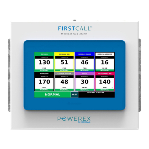
Powerex FirstCall Master Installation and operation manual

Powerex

Powerex FirstCall Master Installation and operation manual

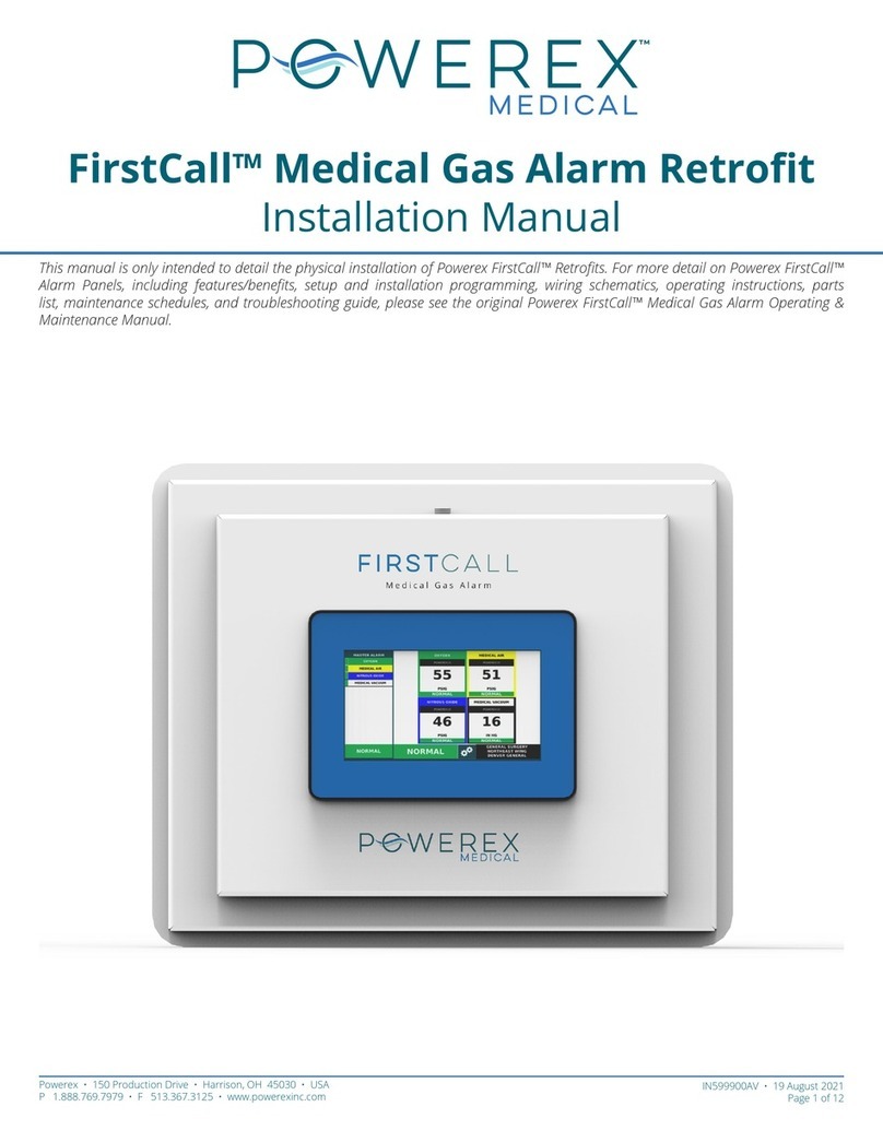
Powerex FirstCall AAP7 Installation and operation manual

Powerex

Powerex FirstCall AAP7 Installation and operation manual

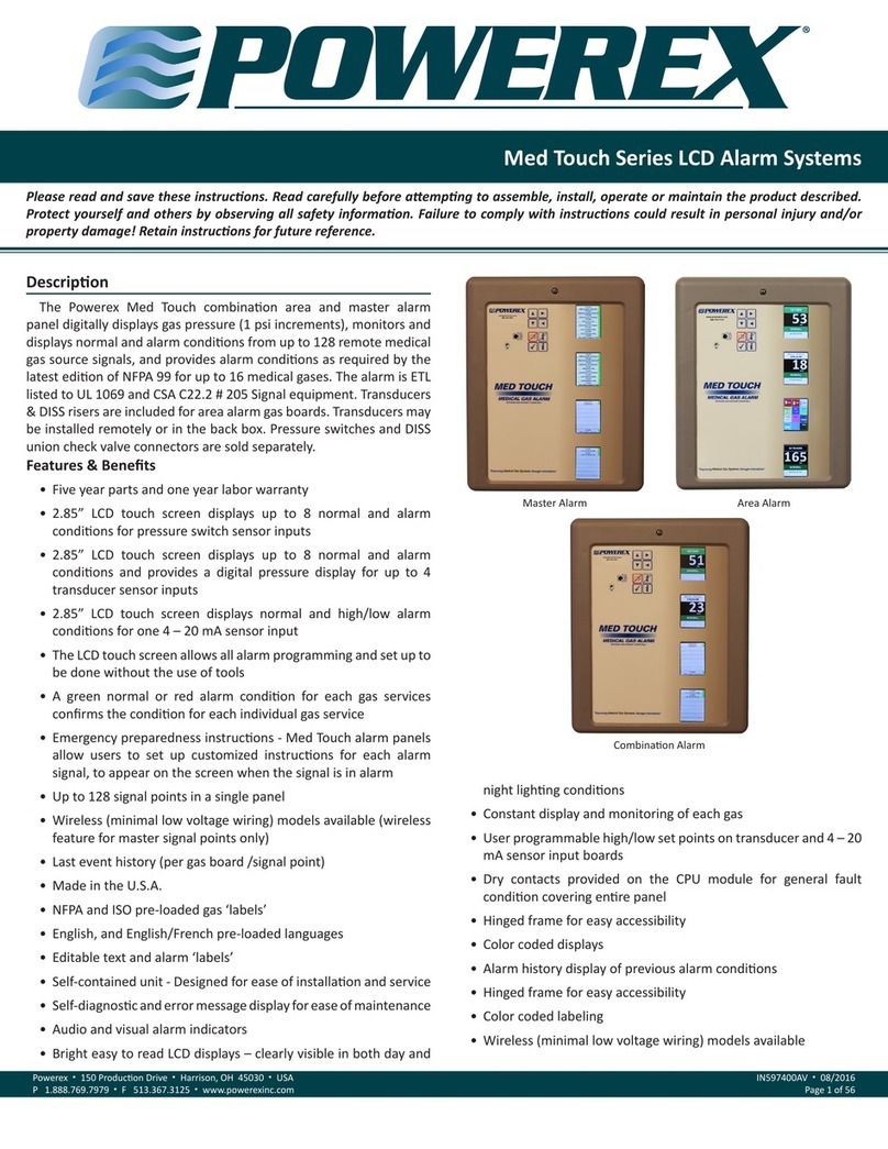
Powerex Med Touch Series User manual

Powerex

Powerex Med Touch Series User manual

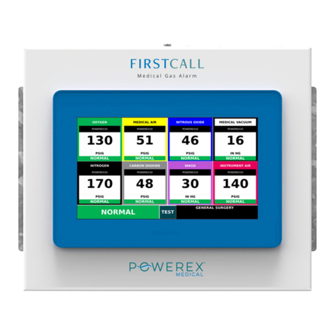
Powerex FirstCall Master User manual

Powerex

Powerex FirstCall Master User manual

Popular Security System manuals by other brands

Pulsar AWZ 710 quick start guide

Pulsar

Pulsar AWZ 710 quick start guide

Pulsar 7/TRP40/DSPR/S Assembly instructions

Pulsar

Pulsar 7/TRP40/DSPR/S Assembly instructions

SEBSON TS ALARM A user manual

SEBSON

SEBSON TS ALARM A user manual

DesignTech Mail Alert 30303 user manual

DesignTech

DesignTech Mail Alert 30303 user manual

Gemini GEM-P800 user guide

Gemini

Gemini GEM-P800 user guide

Protected Home WA-5000 manual

Protected Home

Protected Home WA-5000 manual

Swann DVR4-2500 Specifications

Swann

Swann DVR4-2500 Specifications

Sirena OVOLUX R Series INSTALLATION AND APPLICATION INSTRUCTIONS

Sirena

Sirena OVOLUX R Series INSTALLATION AND APPLICATION INSTRUCTIONS

hamilton safe 5000 series Installation & service manual

hamilton safe

hamilton safe 5000 series Installation & service manual

unotec SAS user manual

unotec

unotec SAS user manual

Lorex LW1741 user guide

Lorex

Lorex LW1741 user guide

S-Access SA-ACU-SR user manual

S-Access

S-Access SA-ACU-SR user manual

GE Security CareGard user guide

GE Security

GE Security CareGard user guide

MobileHelp MD5 Mobile DUO quick start guide

MobileHelp

MobileHelp MD5 Mobile DUO quick start guide

Ecco 6260 Series Installation and operation instructions

Ecco

Ecco 6260 Series Installation and operation instructions

EVE 10EBN9901 manual

EVE

EVE 10EBN9901 manual

Mircom FA-101T Installation and operation manual

Mircom

Mircom FA-101T Installation and operation manual

Brooks Firetracker FT128 CIE Technical/Programming Manual

Brooks

Brooks Firetracker FT128 CIE Technical/Programming Manual

manuals.online logo
manuals.online logoBrands
  • About & Mission
  • Contact us
  • Privacy Policy
  • Terms and Conditions

Copyright 2025 Manuals.Online. All Rights Reserved.