PowerFleet VAC4S Installation manual

Enterprise VAC4 and VAC4S Hardware User’s Guide
085-00000700 Rev K
Page 2 of 100
EnterpriseVehicle
Management System (VMS)
Hardware User’s Guide
An operating and troubleshooting guide for the
VAC4, VAC4S, WAM, and other peripheral hardware
(some features require firmware from system release 08.05.00 or later)
123 Tice Blvd • Suite 101
Woodcliff Lake, NJ 07677
Phone 201.996.9000 • Facsimile 201.996.9144
www.powerfleet.com
©2020 PowerFleet Inc.
085-00000700 Rev K

Enterprise VAC4 and VAC4S Hardware User’s Guide
085-00000700 Rev K
Page 3 of 100
About this Guide
This Guide provides detailed information on the proper use and maintenance of PowerFleet
Enterprise vehicle management system (VMS), including the 4th generation Vehicle Asset
Communicator® (VAC), other vehicle peripheral hardware, and the Wireless Asset Manager (WAM).
Safety
The PowerFleet VMS is not intended for use as a primary safety device. Installation must NOT
adversely affect any vehicle safety system or safety device. The installation, configuration and
operational procedures provided in this Guide are intended for use ONLY by personnel certified on
PowerFleet VMS installation. It is the user’s responsibility to ensure that the procedures in this Guide
are completed by certified personnel ONLY, using the proper tools and following the proper safety
protocols. The procedures and recommendations in this Guide do not supersede any Federal, State
or Local regulations.
Confidentiality Notice
© 2020 PowerFleet, Inc. All rights reserved. This document contains confidential and/or proprietary
information and may be reproduced for the user’s internal training purposes ONLY. This document
may not be reproduced in part, or shown, or in any way disclosed to any third party, without the
express written consent of PowerFleet, Inc.
Disclaimer
The information contained in this Guide is subject to change without notice and should not be
construed as a specification.
Disclaimer and Limitation of Liability
PowerFleet, Inc. assumes no responsibility for any damage or loss resulting from the use of its
products or services. PowerFleet assumes no responsibility for any loss or claims by third parties,
which may arise through using its products or services.

PowerFleet®VAC4 and VAC4S Hardware User’s Guide
085-00000700 Rev K
Page 6 of 103
CONTENTS
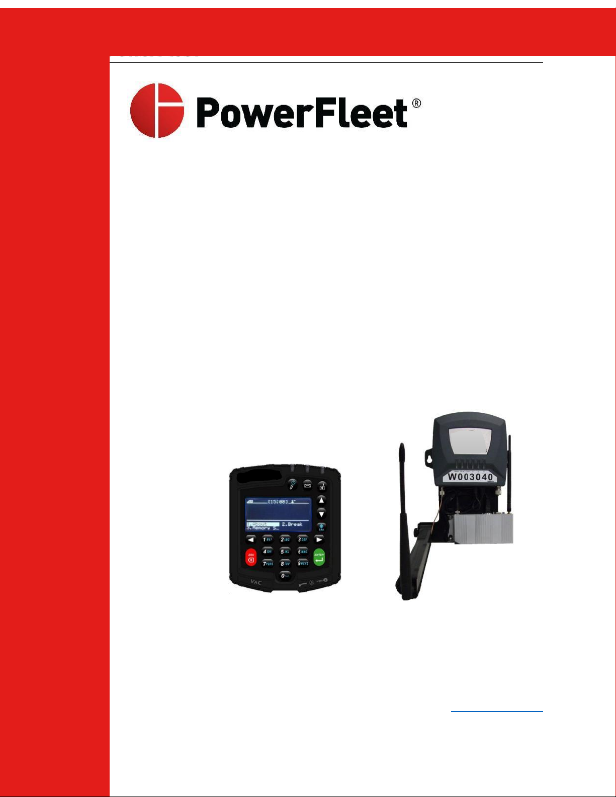
INTRODUCTION....................................................................................................................................................... 8
SECTION 1: SYSTEM OVERVIEW .............................................................................................................................. 9
POWERFLEET ENTERPRISE SYSTEM DIAGRAM...........................................................................................................................................9
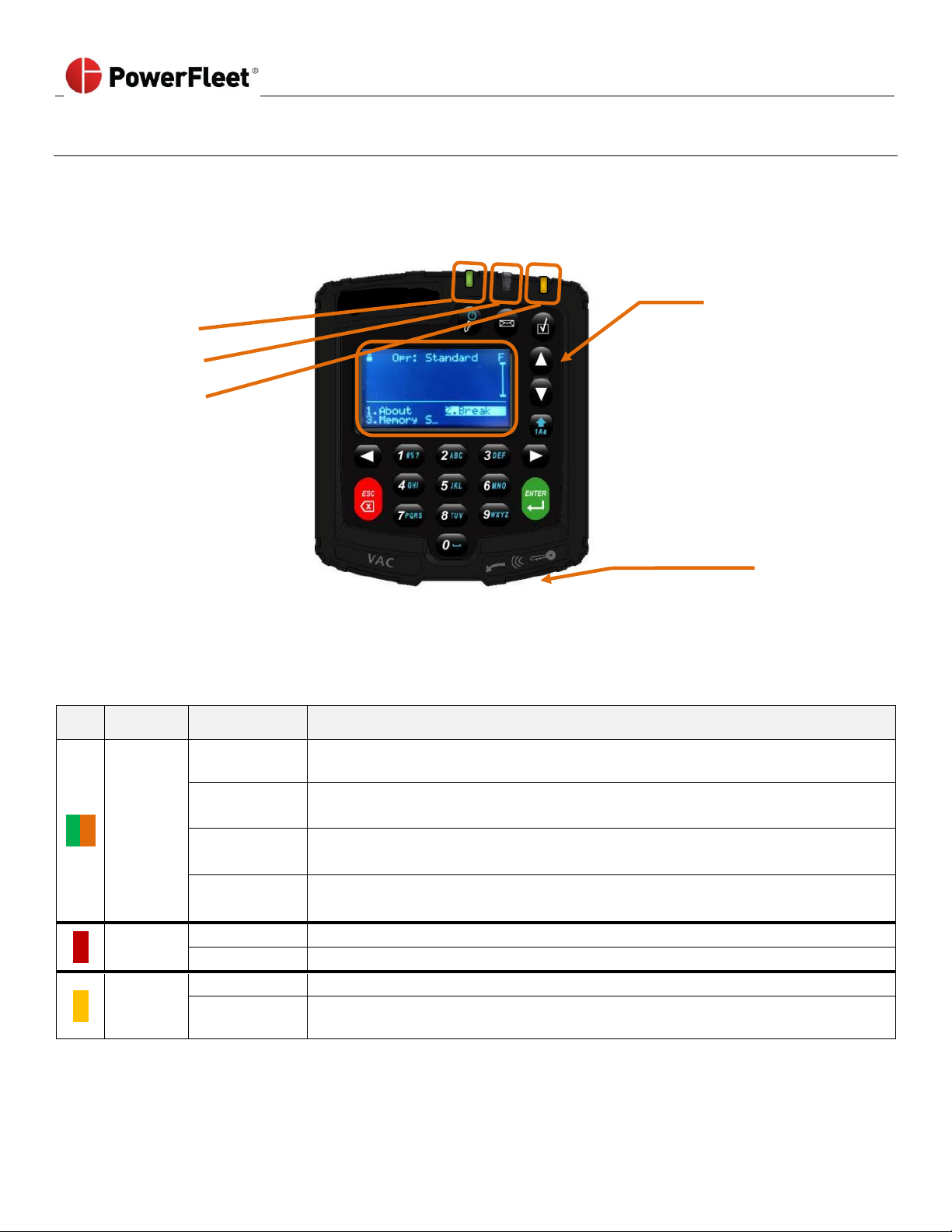
VAC INTERFACE:LCD, KEYPAD,ID READER AND LEDS...........................................................................................................................10
Status Indicators ......................................................................................................................................................................10
MENU SCREENS................................................................................................................................................................................14
DATA INPUT SCREENS........................................................................................................................................................................15
MULTIPLE CHOICE SELECTION SCREENS.................................................................................................................................................16
LOGIN METHODS (VARIOUS METHODS ARE BASED ON WHICH VERSION OF POWERFLEET IS PURCHASED) ............................................................17
SECTION 2: CONFIGURING THE HARDWARE............................................................................................................18
VAC CONFIGURATION .......................................................................................................................................................................18
WI-FI CONFIGURATION ON THE VAC....................................................................................................................................................19
Entering credentials on the VAC using the keypad ..................................................................................................................19
Wirelessly receiving credentials from a nearby Wi-Fi-configured VAC ....................................................................................21
Receiving credentials from a Wireless Asset Manager (WAM)................................................................................................22
VAC SYNCHRONIZATION ....................................................................................................................................................................24
Wirelessly, using Intelligent RF (IRF) ........................................................................................................................................24
Wirelessly, using Wi-Fi .............................................................................................................................................................24
IMPACT SENSOR CONFIGURATION........................................................................................................................................................24
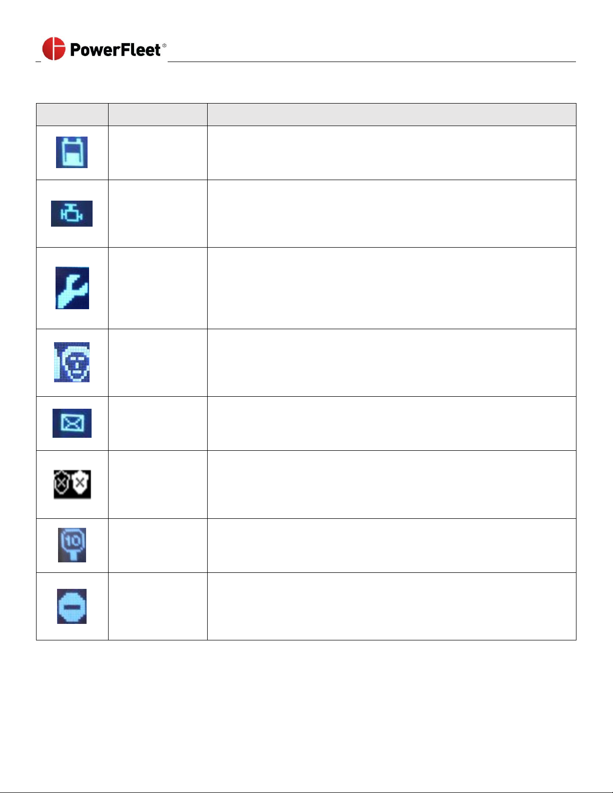
READING VAC “INFO”SCREENS ..........................................................................................................................................................26
SECTION 3: STANDARD OPERATORS.......................................................................................................................28
LOGGING INTO THE VAC (TO START THE VEHICLE) ...................................................................................................................................28
Login Error Code Table [“Error (AXX)” plus below text when login is attempted] ...................................................................29
READING VAC “ABOUT”SCREENS .......................................................................................................................................................30
LOGGING OFF THE VAC.....................................................................................................................................................................31
ANSWERING SAFETY CHECKLISTS..........................................................................................................................................................32
Critical Shutdown.....................................................................................................................................................................34
OPERATING THE VEHICLE....................................................................................................................................................................35
Break Mode..............................................................................................................................................................................35
Idle Timeout .............................................................................................................................................................................35
Automatic Hibernate ...............................................................................................................................................................35
Motion Safety Feature .............................................................................................................................................................36
Event Shutdowns (Impact, safety non-compliance, etc.) .........................................................................................................36
Memory Status.........................................................................................................................................................................36
SECTION 4: MASTER OPERATORS (SUPERVISORS) ...................................................................................................37
Adding Temporary Users..........................................................................................................................................................37
Clearing Event Lockouts ...........................................................................................................................................................39
Checklist Administration ..........................................................................................................................................................40
Manual Vehicle Lock ................................................................................................................................................................41
Manual Vehicle Unlock ............................................................................................................................................................41
SECTION 5: MAINTENANCE OPERATORS ................................................................................................................42
Installation and Configuration .................................................................................................................................................42
VAC Timer Reset After Completed PM .....................................................................................................................................42
Diagnostic Errors......................................................................................................................................................................43
ID Optional (‘Soft’ Bypass) .......................................................................................................................................................44
Read Operator Identification ...................................................................................................................................................45
Replacing an Existing VAC........................................................................................................................................................46

PowerFleet®VAC4 and VAC4S Hardware User’s Guide
085-00000700 Rev K
Page 7 of 103
Checking VAC Synchronization Status......................................................................................................................................47
Reset VAC Synchronization ......................................................................................................................................................48
Changing the VAC Facility ID....................................................................................................................................................49
Forcing the VAC to Low Power Mode (Hibernate) ...................................................................................................................49
Checking VAC Internal Backup Battery (not applicable for all VAC types)...............................................................................50
Changing the VAC Data Transmission Settings........................................................................................................................51
Checking and Changing the VAC Usage Totals ........................................................................................................................52
Testing the BLU wire connection prior to VAC configuration...................................................................................................53
Understand and Manually Set “Motion” for Electric Vehicles .................................................................................................54
Understand and Manually Set “Idling” for Internal Combustion Vehicles ...............................................................................55
Understand and Manually Set “Motion” for Internal Combustion Vehicles ............................................................................56
Current VAC Configuration (“States” Screen) ..........................................................................................................................57
Last VAC Configuration (“InsReport” Screen)...........................................................................................................................60
Impact Sensor Troubleshooting ...............................................................................................................................................62
Manually Enabling Impact Calibration ....................................................................................................................................63
Check Vehicle Battery Voltage Monitoring ..............................................................................................................................63
SECTION 6: WAM USE AND TROUBLESHOOTING ....................................................................................................64
WAM Use .................................................................................................................................................................................64
WAM LEDs Explained ...............................................................................................................................................................64
WAM Troubleshooting.............................................................................................................................................................65
.................................................................................................................................................................................................65
Multitech Modem LEDs Explained ...........................................................................................................................................65
Cradlepoint Modem LEDs Explained ........................................................................................................................................66
Modem Troubleshooting..........................................................................................................................................................66
SECTION 7: VAC TROUBLESHOOTING .....................................................................................................................67
Recommended maintenance tool list.......................................................................................................................................67
VAC to Wired vehicle cable pinout and fuses...........................................................................................................................67
VAC screen and LEDs do not illuminate ...................................................................................................................................67
SECTION 8: SENSOR HUB ERRORS ..........................................................................................................................68
Pinout Diagram........................................................................................................................................................................68
Sensor Hub LED Indicators .......................................................................................................................................................68
Troubleshooting.......................................................................................................................................................................68
SECTION 9: SELF-DIAGNOSTIC ERROR CODES..........................................................................................................69
SECTION 10: SYSTEM SUPPORT INFORMATION ......................................................................................................94
TECHNICAL SPECIFICATIONS –VAC4S AND VAC4 ..................................................................................................................................94
Electrical Specifications............................................................................................................................................................94
Processor/Memory/Other Specifications.................................................................................................................................94
Communication Specifications.................................................................................................................................................95
User Interface Specifications....................................................................................................................................................95
Mounting Specifications ..........................................................................................................................................................96
Sensor Specifications................................................................................................................................................................96
Regulatory and Product Certifications .....................................................................................................................................97
CUSTOMER SUPPORT AND RETURN MERCHANDISE AUTHORIZATION (RMA) POLICY AND PROCEDURES ............................................................99
APPENDIX A(RMA REQUEST FORM)..................................................................................................................................................100
APPENDIX B(HARD-BYPASS POWERFLEET®ACCESS CONTROL) ................................................................................................................101
APPENDIX C(USING THE POWERFLEET WI-FI TEST TOOL)......................................................................................................................102

PowerFleet®VAC4 and VAC4S Hardware User’s Guide
085-00000700 Rev K
Page 8 of 103
INTRODUCTION
This Guide provides the information needed to configure, use, and maintain the hardware included with PowerFleet’s
Enterprise Vehicle Management System (VMS):
VAC
Vehicle Asset Communicator
WAM *
Wireless Asset Manager
Related peripherals
* WAM not required for Wi-Fi deployments.
In addition to this guide, PowerFleet offers many other ways to learn the system including but not limited to:
•Live training webinars
•Interactive self-paced learning modules
•How-to videos
•Technician Certification programs (visit http://go.powerfleet.com/powerfleet-university)
Related Documents
This detailed Guide is a supplement to the following PowerFleet system documents:
Title
Description
PowerFleet Enterprise Getting Started Guide
General system instructions for the site coordinator.
PowerFleet Enterprise Installation Guide
Installation instructions for vehicle hardware.
(Cellular) Wireless Asset Manager Installation Guide
Installation instructions for the WAM.
I.D. Registration form
Associate each operator with assigned fob
Note: The VAC is an interactive mini-computer designed for installation on industrial vehicles. Since vehicle designs vary
widely, this Guide cannot provide precise instructions for each specific vehicle model. Instead, this Guide provides the
basic knowledge needed for a certified installer with a typical installation.
Note: The installation, configuration and operational procedures provided in this document are intended for use by
authorized, certified personnel only. It is the responsibility of the supervisor to ensure that the procedures in this
publication are only completed by trained/certified personnel, using the proper equipment and following the proper
safety protocols.

PowerFleet®VAC4 and VAC4S Hardware User’s Guide
085-00000700 Rev K
Page 9 of 103
SECTION 1: SYSTEM OVERVIEW
PowerFleet Enterprise System Diagram
Placement of a VAC on a vehicle
•VAC must be mounted on the
vehicle where it can be
accessed by the operator
without interfering with any
vehicle operation.
•VAC interfaces with the
vehicle for power, ignition/
access control, and usage
monitoring using an 18-foot
cable harness.
•VAC interfaces with operators
through Access ID readers,
LEDs, a keypad, and a backlit
LCD display.
•VAC communicates
automatically with remotely
hosted software via a WAM
or Access Point, but operates
seamlessly, even when not in
coverage range.
or
Hotspot

PowerFleet®VAC4 and VAC4S Hardware User’s Guide
085-00000700 Rev K
Page 10 of 103
VAC Interface: LCD, Keypad, ID Reader and LEDs
The VAC incorporates a 20-key keypad that is easy to read and operate. The graphical LCD screen remains backlit for
15 seconds after any key is pressed on the keypad. The VAC integrates an electronic identification reader for vehicle
access control. Operators use individual access identification “keys” to the vehicle. (i.e., iButton fobs, prox cards, etc.).
Vehicle keys may still be required, depending on wiring and can be safely left in the vehicle.
Keypad
LEDs
•Access
•Numbers for PIN entry and
menu selection
•Message
•Letters for configuration
inputs
•Checklist
•ARROW keys for scrolling
LCD screen
•ENTER and ESC key - menu
navigation
•Status Header
•Function key
•Alerts/ Icons
•Shortcut keys
•Text
•VAC menu screens
displays: menu
options
Access ID Reader
•Touch ID to log on or log off and assign a Temporary User
Status Indicators
When the VAC is powered, the VAC has three integrated LEDs for operator and supervisor status indication.
LED
Message
LED State
Indication
Access
Off
No one logged in and the vehicle is in Registered ID or Any ID mode
(operators must log in to operate the vehicle).
Blinking
Green
No one logged in and the vehicle is in ID Optional mode
(Anyone can use the vehicle without logging in).
Solid
Green
An operator is logged in
(The vehicle should NOT be left unattended in this state).
Blinking
Green/Orange
The vehicle is locked or about to be locked for certain operator levels
(This occurs due to a vehicle impact or other event).
Message
Off
There are no incomplete tasks, no unread text messages, and no active errors.
Blinking Red
The vehicle has an unread message, task or an active diagnostic error.
Checklist
Off
No one logged in and/or the vehicle is compliant for all configured checklists.
Blinking
Yellow
There is a checklist that needs to be completed.
Note: When the Access, Message, and Checklist LEDs blink in sequence, the VAC is in ‘programming’ mode and cannot
be used by operators. Call PowerFleet’s Support if this condition persists for more than twenty-five minutes.

PowerFleet®VAC4 and VAC4S Hardware User’s Guide
085-00000700 Rev K
Page 11 of 103
The VAC screen displays the current time, text, status icons (top row) and menu options.
Some icons are described as follows:
Icon
Meaning
Indication
Reception Bars
Reception bars provide an indication of signal strength the VAC is currently
experiencing for the wireless communication method which is affected by the
proximity to nearby WAMs or AP’s.
(X without bars = no coverage, 1 bar = weakest, 3 bars = strongest)
IRF Communication
IRF communication icon indicates that the VAC is ready to use or is using
Intelligent RF (IRF) to communicate with the system. If inverted, the VAC has data
to send to a WAM but is unable to do so using IRF. IRF is a proprietary 868/915
MHz technology. Refer to reception bars to determine communication strength.
Wi-Fi
Communication
Wi-Fi communication icon indicates that the VAC is ready to use or is using Wi-Fi
to communicate with the server. If inverted, the VAC has data to send to the
server but is unable to do so using Wi-Fi. Refer to the reception bars to determine
the strength of the communication.
GPS Triangulation
GPS triangulation icon indicates that the VAC has triangulated its location with
GPS satellites. Direction is found through this navigational aid.
OEM CAN
Communication
OEM CAN communication icon indicates that the VAC is configured to
communicate with a CAN equipped vehicle. If only the arrow pointed to the right
is visible, the VAC has not recently received data from the CAN (such as when
the key is off). If only the arrow pointed to the left is visible,
communication with the CAN is failing.
Time Clock
The time clock (bracketed) indicates the current local time (24-hour clock format).
The time is replaced by a countdown when a safety checklist has to be
completed. If the time is blank [--:--], the VAC does not yet know the local time
zone such as when it is first installed and yet to communicate to the system.
Logged-in Operator
Authorization Level
Logged-in operator authorization level indicators are inverted icons (black on
white) when the operator is not recognized in the system software (i.e. new
IDs in “Any ID” mode)
Operator - 1 box
STANDARD
The Standard operator logged in.
Operator - 2 Boxes
MASTER
The Master operator logged in.
Operator - 3 Boxes
MAINTENANCE
The Maintenance operator logged in.
Operator - 4 Boxes
ADMINISTRATION
The Administrator logged in (IDSY personnel only).
Operator - IT
IT
An IT operator logged in.
Diagnostic
Error
The Diagnostic Error icon is accompanied by a flashing red LED on top of the VAC.
At least one REFERENCE or FUNCTIONAL diagnostic error (i.e. Impact sensor
error) is active on the vehicle. However, these errors Do Not lock the vehicle or
prevent operator use of the VAC.
Diagnostic
Error
(Lockout)
The Diagnostic Error icon is accompanied by a flashing red LED on top of the VAC.
The vehicle is Locked Out for all operators except Maintenance users. At least one
SAFETY/ SHUTDOWN diagnostic error (i.e. Vehicle not correctly configured for
motion) is active on the vehicle and there is a driver safety risk.

PowerFleet®VAC4 and VAC4S Hardware User’s Guide
085-00000700 Rev K
Page 12 of 103
The VAC indicates different vehicle and VMS system conditions in the main screen using text as well as iconography
(some with animation). Common icons include the following:
Icon
Meaning
Indication
Battery
The Hourglass icon:
New battery request is being processed.
Break
The vehicle is in Break mode.
This feature is used to keep the vehicle from being borrowed during short
breaks. The break time is typically 15 minutes. The one operator sets the
vehicle in Break mode and only a Master operator or a Maintenance operator
can log in until the Break time expires.
Checklist
The Checklist icon is accompanied by a blinking yellow indicator LED. The
checklist icon is also sometimes accompanied by a grace period timer
indicating how long (in minutes) before a non-compliance event is created.
The same countdown will also appear in the Status Header. The vehicle has an
active checklist that requires a Standard operator to complete.
Diagnostics
The blinking Diagnostic icon is accompanied by a blinking red LED.
The vehicle has active Diagnostic errors. A Maintenance operator must correct
and clear the error, or, in some cases, the error will clear itself.
See section 7, VAC Troubleshooting, for more details on diagnostic errors.
GPS
When the GPS icon is displayed, the vehicle cannot determine location using
the GPS sensor.
Make sure the GPS sensor is connected and configured properly and that the
GPS receiver has a clear line of site to a satellite symbol.
Impact
The Impact icon is accompanied by a blinking yellow indicator LED.
The vehicle has an active impact event. When displayed on its own, the impact
event did not result in a lockout and standard operator feedback is required by
completing a checklist.
Lockout
The Lockout icon is accompanied by an alternating, blinking Green/ Orange
LEDs.
The vehicle is locked and can only be logged into using Master or Maintenance
operator credentials.

PowerFleet®VAC4 and VAC4S Hardware User’s Guide
085-00000700 Rev K
Page 13 of 103
Common icons include the following:
Icon
Meaning
Indication
Low
Battery
The Low Battery icon:
The vehicle battery is low and requires a charge.
Low Oil Pressure
High Engine
Temperature
The Engine icon:
The oil pressure or engine temperature inputs (VIMs 10 and 11) are outside the
normal range. Check the engine for low oil or coolant.
Maintenance
The Maintenance icon is accompanied by an alternating, blinking Green/
Orange LEDs.
The vehicle is locked and can only be logged into using a Maintenance operator
credentials.
Master
The Master icon is accompanied by a blinking yellow LED.
The vehicle has an active checklist that requires a Master or Maintenance
operator to complete.
New
Message
The New Message icon is accompanied by a blinking red LED.
A new message was received for the vehicle and/or operator. Once the
message is read, the icon disappears.
Shield
The blinking Shield icon:
The vehicle is in Emergency Access mode, indicating that any operator can
access and operate the vehicle without logging in through the VAC.
Speeding
The Speeding icon:
The operator was driving over the configured speed limit. The icon will
disappear once the vehicle decelerates to an acceptable speed level.
Zone
The Zone icon:
The operator has driven the vehicle inside a restricted area. Drive the vehicle
out of the restricted area to clear the icon.

PowerFleet®VAC4 and VAC4S Hardware User’s Guide
085-00000700 Rev K
Page 14 of 103
Menu Screens
The Menu screens allow the operator to read and scroll through multiple lines of text as well as rapidly scan through and
select the menu item of choice.
Status Header
Scroll indicator vertical bar
with handle
Up and Down ARROW keys
scroll through available text
rows (if handle displayed).
(Returns to the top row when
advancing past the last row)
Text related to VAC
menu options
Left and Right ARROW keys
scroll through menu options,
and additional pages when
the left pointed arrow or
right pointed arrow (→ or ←)
are displayed next to the first
or last menu item.
(menu options displayed
Wraps beginning-end and
end-beginning)
Horizontal line separating
text and available responses
(Each section auto-resizes
based on the number of
menu options)
Current selected response is
highlighted
ENTER key confirms the
highlighted selection and
advance to the next screen.
Quick press: ESC key exits to
the previous screen
Long press: ESC key exits to
the home screen
Screen Display (first page)
Quick press: Highlights menu option corresponding to key pressed, then ENTER must be pressed to make the
selection. Long press: Press and hold on the number keys that corresponds to the menu option advances to the next
screen, without pressing ENTER.
The following is an example of the Quick Press or Long Press feature:
1.
Press and HOLD the 2 button for more than 2 seconds to highlight the menu option.
Select 2. OK to advance to the next screen.
~ OR ~
2.
Press the right arrow button to move the highlighted selection from:
Select 1. UPDATE
Select 2. OK
Then press ENTER.
~ OR ~
3.
Press the 2 button to highlight
Select 2. OK. Then press ENTER.

PowerFleet®VAC4 and VAC4S Hardware User’s Guide
085-00000700 Rev K
Page 15 of 103
Data Input Screens
Data input screens allow the operator to enter data when prompted by the VAC system.
Status Header
Scroll indicator vertical bar
Up and Down ARROW keys
scroll through available rows
(Returns to the top row
when advancing past the last
row)
Data prompt
Character toggle key -
up arrow:
1: numeric characters
A: upper case alpha/
symbols*
a: lower case alpha/
symbols*
Character replaced by any
text entry. (Blinking cursor)
Text currently available for
text entry (Highlighted)
Left and Right ARROW keys
move blinking cursor left or
right
Quick press: ESC key exits to
the previous screen
Long press: ESC key exits to
the home screen
Quick press: ENTER key
confirm the entered text,
proceed to the next text
entry row (if applicable), or
advance to the next screen if
on the last row
Long press: ENTER key
advance to the next screen
from any position
Enter alphanumeric characters in the currently selected mode.
(Cursor auto-advances one character if no key is pressed for more than 1 second)
(Cursor auto-advances one character if a different key is pressed than the previous)
* Common symbols used during text entry are as follows:
•0= [space] when not in numeric entry mode.
•1= symbols when not in numeric entry mode.
Mode
Symbols
a (lower case) mode
= + - * / ( ) { } [ ] % < >
A (upper case) mode
? , @ ! : . # _ \ & “‘; ^ | $ ~

PowerFleet®VAC4 and VAC4S Hardware User’s Guide
085-00000700 Rev K
Page 16 of 103
Multiple Choice Selection Screens
Multiple choice selection screens allow the operator to pick one item from a list which is similar to a pick list.
Status Header
Scroll indicator vertical bar
Up and Down ARROW keys
scroll through available
choices.
(Returns to the top row
when advancing past the last
row)
Ordinal position of item
currently highlighted
(1st of 13) followed by 12
additional menu screens
with instructions
Highlighted item is currently
selected
Quick press: ESC key exits to
the previous screen
Long press: ESC key exits to
the home screen
ENTER key confirms the
selected item, advance to
the next screen.

PowerFleet®VAC4 and VAC4S Hardware User’s Guide
085-00000700 Rev K
Page 17 of 103
Login Methods (various methods are based on which version of PowerFleet is purchased)
iButton ID Fobs –Each Operator Access Level has a designated ID fob
Black iButton ID is for regular vehicle operators (STANDARD operators)
Features enabled are: login; safety inspection checklist; “Break” feature (for temporary control of
vehicle during short breaks); check memory status; log off (VAC LOGOFF button).
Blue iButton ID is for supervisors (MASTER operators)
Features are the same as Standard Operators, PLUS: “Temp Users” feature (to add otherwise
unauthorized drivers temporarily); lock out vehicles from use by Standard Operators; unlock
vehicles locked due to severe impacts or non-compliance; change compliance status.
Yellow iButton ID is for maintenance personnel (MAINTENANCE operators)
Features same as Supervisors, PLUS: configure/re-configure the VAC including Wi-Fi and sensors;
complete Preventative Maintenance (PM) checklist; lock out vehicles from use by Standard
operators and Supervisors; bypass vehicle access control (i.e. during vehicle maintenance); unlock
vehicles locked out for any reason; troubleshoot and clear diagnostic errors; read operator IDs;
manually define or troubleshoot sensor settings.
Access IDs
Note: Access IDs are often
provided by the end user.
When the system is in “Any ID” access mode (default configuration when the VAC is shipped), an access ID creates a
“Place Holder” operator profile in the PowerFleet Vision Pro™ software when first presented to a VAC and the operator
is granted access to the vehicle as a Standard operator. The place holder profiles are associated with the ID’s embedded
identification number and can be updated with actual operator information (name, password, authorization level, etc.)
at the customer’s discretion. Alternatively, operator profiles can be added directly to the software (in “Any ID” mode or
“Registered ID” mode) by presenting the access IDs to the desktop Access ID Reader. Refer to the PowerFleet Vision Pro
training video for more details.
To access the vehicle as a Master or Maintenance level operator, the numeric operator ID and password using the VAC
keypad must be entered. The ID numbers can be found in the installation documentation. The software should be used
to assign individuals’ ID’s as Master or Maintenance operators.
Note: Each iButton fob has a unique operator ID. The
operator with the personal fob must be accurately
recorded.
Each fob is assigned and distributed to each operator.
Note the name of the operator AND the fob’s ID number
(or the fob’s ID label can be peeled off and placed next to
the operator’s name) on the provided I.D. Registration
form (Refer to 000-00000495 document). Later, that
data can be entered into the PowerFleet software to
associate each operator with his/her fob.
000-00000495 document:

PowerFleet®VAC4 and VAC4S Hardware User’s Guide
085-00000700 Rev K
Page 18 of 103
SECTION 2: CONFIGURING THE HARDWARE
VAC Configuration
A VAC equipped vehicle cannot be used by the Standard or Master operators until the VAC has been successfully
configured by a Maintenance operator for the BASIC configuration wizard. The VAC on-screen message and blinking red
LED is displayed. (Note: instructions for testing the BLU wire connection prior to VAC configuration are in Section 5).
Once the PowerFleet Enterprise vehicle hardware has been properly installed, the vehicle can only be accessed using the
yellow maintenance IDs, or a Maintenance level operator login. When a Maintenance operator logs in, they will be
required to follow a series of VAC screen display instructions displayed to verify the installation and configuration. This
process time is about 3 to 5 minutes and requires the operator to perform the following:
1. Enter or confirm the Facility ID. This number is unique to the facility where your system is operating. For VACs in
your facility with the incorrect Facility ID, there will be no communication to the system infrastructure.
•Your facility ID was communicated to the system coordinator with your software access credentials.
•If you enter a zero on the facility ID screen, the IRF VACs will assign the facility ID of the first WAM it
communicates with (while on the facility ID screen).
•If you do not know the facility ID, contact PowerFleet’s Support.
2. Enter or confirm your license key (based on features purchased).
•License key was communicated to the system coordinator with the assigned software access credentials.
•If you do not know the facility ID, contact PowerFleet’s Support.
3. Select vehicle type:
FR
Forklift Rider
OP
Order Picker
SE
Sweeper
TR
Turret Truck
FS
Forklift Stand-up
PC
Preconditioned Air
SR
Stacker Rider
TT
Tow Tractor
GP
Ground Power Unit
PR
Pallet Jack Rider
SW
Stacker Walkie
TV
Truck/ Van
JB
Jet Bridge
PW
Pallet Jack Walkie
TH
Other
ML
Man Lift
RT
Reach Truck
TL
Towbarless Tow
4. Enter the vehicle label number. The numeric value is between 1 and 65534.
5. Select a vehicle Engine Type (VDI CAN interface VACs skip steps 5-7 and drive tests):
Electric
Electric motor
Gas/IC
Internal combustion
iPort
iPort enabled Raymond electric
6. Select what the Green and Yellow wires are connected to for access control:
On/Off Relay
Relay supplied with kit
Vehicle PWM Circuit
Connected to vehicle circuit with PWM
7. For Electric vehicles, select the BLU wire input type (where the BLU wire was connected to):
V (Avg)
Voltage average mode
V (min/max)
Voltage minimum/maximum mode
8. Follow the VAC Configuration Wizard’s VAC screen display prompts for performing vehicle actions (i.e. start
vehicle, release brake, drive forward, drive in reverse, etc.)
Once the VAC has been configured without errors, the VAC is active in “Any ID”
mode and any hardware-compatible ID can access the vehicle. In Any ID mode, the
system will NOT lock out vehicles due to impacts, critical checklist responses, etc. If
you are unsure which mode the system is in, check the operator icon in the header
of the VAC screen when logged in or Maintenance operators can determine the
current VAC mode using the Access menu. (Any ID mode has the icon color inverted)
(See ‘ID Optional’ in Section 5: Maintenance Operators for more details).
Note: If the configuration fails and an error message is displayed, refer to Section 7: VAC Troubleshooting.

PowerFleet®VAC4 and VAC4S Hardware User’s Guide
085-00000700 Rev K
Page 19 of 103
After the “BASIC” wizard is complete, continue to the “SENSOR” wizard.Refer to the VAC installation Guide for more
details on sensor configuration.
Wi-Fi Configuration on the VAC
PRIOR TO CONFIGURING VACS FOR YOUR WI-FI SYSTEM, VALIDATE YOUR NETWORK CONFIGURATION WITH THE
POWERFLEET'S WI-FI TEST TOOL.
THERE ARE TWO TEST TOOLS AVAILABLE. THE SMART PHONE APP (SEARCH "VMS TOOLS" IN THE ITUNES OR GOOGLE
PLAY APP STORES) IS THE PREFERRED METHOD. A PC-BASED VERSION IS ALSO AVAILABLE THROUGH THE I.D. SYSTEM
CUSTOMER PORTAL (or email support@powerfleet.com). APPENDIX C OF THIS DOCUMENT CONTAINS INSTRUCTION.
VACs equipped with Wi-Fi can be configured with the desired Wi-Fi security credentials and server information any time
the VAC is powered. There are four ways Wi-Fi credentials can be applied:
•Entering credentials on the VAC using the keypad.
•Wirelessly receiving credentials from a nearby Wi-Fi-configured VAC.
•Receiving credentials from a Wireless Asset Manager (WAM).
Entering credentials on the VAC using the keypad
1. Log into the VAC as a Maintenance operator or IT operator.
2. From the VAC main menu screen, Select Wi-Fi.
3. If the VAC is in range of wireless networks, a list will appear on the VAC screen. Otherwise, OFF is displayed.
4. The VAC’s default Wi-Fi configuration uses DHCP.
•To configure the VAC using DHCP, skip to step 6.
•To configure the VAC to use a Static IP address, complete step 5.
5. From the VAC menu screen, select VAC IP. Select STATIC. When prompted, enter the requested IP, Subnet Mask,
and Default Gateway values. Use leading zeros as appropriate (For example, if the IP Address is “150.215.17.9”
the value entered into the VAC should be “150.215.017.009”). After providing the requested Static IP values,
press ENTER to proceed to the next screen.
6. To identify the Server to connect with, VAC menu screen, select SERVER IP. Select the server IP ‘type’ (Static IP
or Domain Name), then type in the prompted data using either the Server IP or Domain Name. In both cases,
the Server Port must be entered and a selection made for TLS encryption (TLS encryption or Proprietary as
coincides with you software). For IDSY-hosted systems, this information is provided by PowerFleet.
Note: If steps 4 through 6 are not performed in the proper order, the VAC will not connect to the server of access point.

PowerFleet®VAC4 and VAC4S Hardware User’s Guide
085-00000700 Rev K
Page 20 of 103
7. From the VAC menu screen, select CONNECT.
8. Connect to the facility’s wireless network.
a. If the VAC display lists the desired SSID, use the up and
down scroll arrows keys to select the desired SSID from
the list.
9. Enter the Key for Wi-Fi Credentials.
i. Press ENTER.
ii. Enter the credentials for the selected SSID in
the locations provided. Use the navigation
arrows to skip to different areas of the text
entry boxes.
Note: For WEP credentials, 10 or 26 HEX (0-9;A-F) characters must be entered (ASCII entry not permitted).
iii. Press ENTER.
iv. The VAC will automatically attempt to connect to the selected SSID using the credentials provided.
b. If the VAC display does not list the desired SSID, select
OTHER. Press ENTER.
i. Using the VAC keypad, manually enter the SSID.
ii. Select the security method that corresponds
with the SSID.
iii. Enter the credentials for the SSID.
Note: For WEP credentials, 10 or 26 HEX (0-9; A-F) characters must be entered (ASCII entry not permitted).
iv. The VAC will automatically attempt to connect to the SSID using the credentials provided.
Note: To successfully connect, the VAC must be within wireless communication range of the SSID.
10. Once connected, the VAC screen displays the Wi-Fi status indicator.
11. For instruction on how to broadcast the VAC’s Wi-Fi credentials to nearby VACs that have not been configured,
refer to the next section: Wirelessly receiving credentials from a nearby Wi-Fi-configured VAC.

PowerFleet®VAC4 and VAC4S Hardware User’s Guide
085-00000700 Rev K
Page 21 of 103
Wirelessly receiving credentials from a nearby Wi-Fi-configured VAC
1. Select a VAC that has been configured with the
desired Wi-Fi profile.
2. Log into the VAC as a Maintenance operator or IT
operator.
3. From the VAC main menu screen, select Wi-Fi.
a. To broadcast the VAC’s Wi-Fi configuration to
other VACs, select TRANSMIT.
b. To confirm broadcast of the VAC’s Wi-Fi
configuration, select YES.
The VAC will return to the main Wi-Fi screen.
A “Share” icon will appear to the right of the SSID name.
•For the next 24 hours, that VAC will transmit its Wi-Fi profile to any VAC that comes within wireless communication
range.
•All Wi-Fi profile components (SSID, credentials, server IP/ port, etc.) are transmitted.
•VACs must be configured with the same facility code and RF frequency to successfully send and receive a
transmitted Wi-Fi profile.
•Recipient VACs must be within wireless range of the sending VAC for approximately 1 minute to receive the
transmitted Wi-Fi profile.
•Depending on obstructions and environment, the average wireless sharing range is 500 feet.
•The VAC will automatically begin trying to connect with the newly received profile once a recipient VAC receives the
credentials.
•To force the VAC to stop transmitting, from the main Wi-Fi menu option, select STOP TRANSMIT. Otherwise, the
VAC will stop transmitting on its own after 24 hours.
•The VAC will only transmit credentials typed into it, or received from another VAC. It will not transmit credentials
synchronized from the software nor enterprise certificates.

PowerFleet®VAC4 and VAC4S Hardware User’s Guide
085-00000700 Rev K
Page 22 of 103
Receiving credentials from a Wireless Asset Manager (WAM)
1. Log into PowerFleet Vision Pro software.
4. Scroll down to the Wi-Fi section for Wi-Fi data upload information.
5. Verify that the Wi-Fi information is correct. If the information needs to be updated, click “Edit”on the bottom
right frame of the window.
6. Update Wi-Fi Security credentials.
7. Verify the correct Wi-Fi security parameters are entered.
8. Click Save on the bottom right frame of the window.
2. Access the System
Configuration
module by selecting
the Settings icon in
the top right frame.
3. Select “System
Settings”.
9. To synchronize the
Wi-Fi profile(s),
navigate to Vehicles
setup by selecting
the Assets drop
down window in the
top frame.
10. Select Vehicles.

PowerFleet®VAC4 and VAC4S Hardware User’s Guide
085-00000700 Rev K
Page 23 of 103
To confirm the status of the synchronization for a specific VAC, perform the following:
a. Navigate to Vehicles by selecting the Assets drop down window in the top frame.
b. Select Vehicles.
c. Navigate to the Troubleshooting section and compare the current tran codes to the synched tran codes,
if they are the same the item has been synchronized.
To view the synchronization status of all vehicles:
a. Select Reporting in the top right frame.
b. Scroll down to the Reports List to select System Settings and Diagnostics.
c. Select”Vehicle Synchronization Detail” to run the verification report.
11. Click Sync in the top right frame.
Wait 15 seconds for the synchronization to
complete. The VAC will automatically synchronize
the Wi-Fi profile(s) entered when in wireless
communication range of the WAM.
This manual suits for next models
1
Table of contents
Other PowerFleet Automobile Accessories manuals
Popular Automobile Accessories manuals by other brands

Avenger
Avenger ST250-1400 Fitting instructions

DRAGONFIRE
DRAGONFIRE 04-0045 installation instructions

14POINT7
14POINT7 UAFC user manual

CrimeStopper
CrimeStopper SV-5500 PC-B installation instructions

TOP VEHICLE TECH
TOP VEHICLE TECH GRKST05 installation manual

Thule
Thule Cascade XT 676XT installation instructions