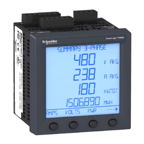
PowerLogic PM-600 User manual

Instruction Bulletin
3020IM9503R6/98
December 1998
(Replaces 3020IM9503R8/97 dated October 1997)
Power Meter
Class 3020

!
DANGER
WARNING
!
CAUTION
!
Used where there is a hazard of bodily injury or death. Failure to follow a
“WARNING” instruction can result in death or bodily injury.
Used where there is a hazard of equipment damage. Failure to follow a
“CAUTION” instruction can result in damage to equipment.
Used where there is a hazard of severe bodily injury or death. Failure to
follow a “DANGER” instruction
will
result in death or
severe
bodily injury.
TECHNICAL SUPPORT
For technical support, contact the
Power Monitoring and Control Systems Technical Support Center.
Hours are 7:30 A.M. to 4:30 P.M., Central Time, Monday through Friday.
www.powerlogic.com BBS: (615) 287-3414
Fax: (615) 287-3404 Phone: (615) 287-3400
POWERLOGIC, POWERLINK, Square D, and are Registered Trademarks of Square D Company.
System Manager is a trademark of Square D.
Other names are trademarks or service marks of their respective companies.
1998 Square D. All rights reserved. This bulletin may not be copied in whole or in part, or transferred
to any other media without the written permission of Square D Company.
FCC NOTICE: This equipment complies with the requirements in Part 15 of FCC
rules for a Class A computing device. Operation of this equipment in a residential
area may cause unacceptable interference to radio and TV reception, requiring the
operator to take whatever steps are necessary to correct the interference.
PLEASE NOTE: Electrical equipment should be serviced only by qualified electrical
maintenance personnel, and this document should not be viewed as sufficient for
those who are not otherwise qualified to operate, service, or maintain the equipment
discussed. Although reasonable care has been taken to provide accurate and
authoritative information in this document, no responsibility is assumed by Square D
for any consequences arising out of the use of this material.
NOTICE
Read these instructions carefully and look at the equipment to become familiar with
the device before trying to install, operate, or maintain it. The following special
messages appear throughout this bulletin to warn of potential hazards.

Registration Card
Register your POWERLOGIC Power Meter today and get:
• Free expert technical phone support—just call (615) 287-3400
• Advance notice on product upgrades and new product releases
• Advance notice on special product offers and price discounts
Name _______________________________ Dept./Title _________________________________
Company _______________________________________________________________________
Address _________________________________________________________________________
City ____________________________________________________________________________
State _________ Country ____________________ Zip/Postal Code ______________________
Telephone _____________________________ Fax ___________________________________
Product Purchased Through (Distributor) _______________________________________________
Register your Power Meter
Please fill out, detach, and mail the postage paid card below. Fill out
only one registration card, even if you have purchased multiple
POWERLOGIC Power Meters.

BUSINESS REPLY MAIL
FIRST CLASS MAIL PERMIT NO. 635 PALATINE, IL
POSTAGE WILL BE PAID BY ADDRESSEE
SQUARE D COMPANY
ATTN CUSTOMER SERVICE
295 TECH PARK DRIVE
SUITE 100
LaVERGNE, TN 37086
®

Bulletin No. 3020IM9503R6/98 Power Meter
December 1998 Contents
Contents
Chapter 1—Introduction ...................................................................... 1
What is the Power Meter? ................................................................................ 1
Using This Bulletin............................................................................................ 3
Notational Conventions ................................................................................ 3
Not Covered in this Bulletin .......................................................................... 3
Chapter 2—Safety Precautions ........................................................... 5
Chapter 3—Hardware Description ...................................................... 7
Display.............................................................................................................. 7
Power Meter Connections .............................................................................. 10
Chapter 4—Installation .......................................................................11
Power Meter/Display Mounting Options ......................................................... 11
Mounting the Display...................................................................................... 12
In Existing 1% Ammeter/Voltmeter Cutout.................................................. 12
On Panel Without Existing 1% Ammeter/Voltmeter Cutout ........................ 13
Mounting the Power Meter ............................................................................. 14
Directly Behind the Display......................................................................... 14
Remote Mounting ....................................................................................... 16
DIN Rail Mounting ...................................................................................... 18
Chapter 5—Wiring .............................................................................. 21
Wiring CTs, PTs, and Control Power .............................................................. 21
Control Power Transformer (CPT) Sizing ................................................... 22
Control Power Fuses .................................................................................. 22
Metering Potential Transformers (PTs) ....................................................... 22
CE Compliance........................................................................................... 22
Deriving Control Power from Phase Voltage Inputs ................................... 31
Grounding the Power Meter ........................................................................... 32
Solid-State KYZ Pulse Output ........................................................................ 33
Chapter 6—Communications ............................................................ 35
Protocols ........................................................................................................ 35
POWERLOGIC Protocol Communications Wiring ......................................... 35
Connecting to a Personal Computer via POWERLOGIC Communications....
36
Connecting to a POWERLOGIC Network Interface Module (PNIM) Using
POWERLOGIC Communications ............................................................. 37
Connecting to a SY/MAX Programmable Controller Using
POWERLOGIC Communications ............................................................. 38
Modbus RTU Protocol .................................................................................... 39
Jbus Protocol ................................................................................................. 39
Connecting to a PC Using Modbus or Jbus Communications ....................... 40
Length of the Communications Link (POWERLOGIC, Modbus, or Jbus) ...... 41
Daisychaining PM&CS Devices (POWERLOGIC, Modbus, or Jbus) ............ 41
Biasing the Communications Link (POWERLOGIC, Modbus, or Jbus) ......... 42
Terminating the Communications Link (POWERLOGIC, Modbus, or Jbus) .. 44

Power Meter Bulletin No. 3020IM9503R6/98
Contents December 1998
Chapter 7—Display Operation........................................................... 47
Introduction .................................................................................................... 47
Modes............................................................................................................. 47
Accessing a Mode ...................................................................................... 48
Setup Mode ................................................................................................ 49
Resets Mode............................................................................................... 50
Diagnostics Mode ....................................................................................... 50
Display Modes ............................................................................................ 50
How the Buttons Work ................................................................................ 51
Mode
Button............................................................................................ 51
Arrow Buttons.......................................................................................... 51
Select
Button........................................................................................... 51
Contrast Button ....................................................................................... 51
Setting Up the Power Meter ........................................................................... 52
Performing Resets ......................................................................................... 54
Viewing Diagnostic Information ...................................................................... 55
Using Display Modes ..................................................................................... 55
Setting Up Onboard Alarms (PM-650 only) .................................................... 55
ViewingActive Alarms (PM-650 only)............................................................. 56
Chapter 8—Metering Capabilities ..................................................... 57
Real-Time Readings....................................................................................... 57
Min/Max Values (PM-650 Only)...................................................................... 57
Power Factor Min/Max Conventions .............................................................. 58
Energy Readings............................................................................................ 61
Power Analysis Values ................................................................................... 62
Demand Readings (PM-620 and PM-650 Only) ............................................ 63
Demand Power Calculation Methods ......................................................... 63
Sliding Block Interval Demand ................................................................ 63
Block Interval Demand with Subinterval Option ...................................... 64
Synch to Comms..................................................................................... 64
Predicted Demand ...................................................................................... 64
Peak Demand ............................................................................................. 64
KYZ Pulse Output .......................................................................................... 65
Calculating the Pulse Constant .................................................................. 65
Chapter 9—Onboard Alarming (PM-650 Only) ................................. 66
Setpoint-Driven Alarms .................................................................................. 66
Setpoint-Controlled Relay Functions.............................................................. 67
Undervoltage .............................................................................................. 68
Unbalance Current ..................................................................................... 68
Unbalance Voltage ..................................................................................... 68
Chapter 10—Logging (PM-650 Only) ................................................ 69
Alarm Log ....................................................................................................... 69
Event Log ....................................................................................................... 69
Data Log......................................................................................................... 69
Alarm-Driven Data Log Entries ...................................................................... 69
Storage Considerations.................................................................................. 69

Bulletin No. 3020IM9503R6/98 Power Meter
December 1998 Contents
Appendices
Appendix A—Specifications ............................................................................... 70
Appendix B—Dimensions .................................................................................. 72
Appendix C—Communication Cable Pinouts .................................................... 73
Appendix D—Additional Wiring Diagrams ......................................................... 74
Appendix E—Using the Command Interface ..................................................... 79
Appendix F—Register List ................................................................................. 81
Appendix G—Modbus and Jbus Functions Supported.................................... 101
Appendix H—2-Wire Modbus or Jbus ............................................................. 103
Appendix I—Alarm Setup (PM-650 Only) ........................................................ 104
Appendix J—Calculating Log File Size (PM-650 Only) ................................... 108
Illustrations
3-1: Power meter display components.............................................................. 8
3-2: Power meter display, front and back.......................................................... 9
3-3: Front of power meter and terminal shield label........................................ 10
4-1: Mounting power meter and display on panel with
existing ammeter/voltmeter cutout ....................................................... 15
4-2: Mounting power meter on panel with no existing cutout .......................... 17
4-3: Panel mount for the power meter display ................................................ 17
4-4: Mounting power meter on 35 mm DIN rail ............................................... 19
5-1: Clamp-on ferrite and disconnect breaker for CE compliance .................. 23
5-2: Opening the clamp-on ferrite ................................................................... 23
5-3: 3-phase, 3-wire delta direct voltage connection with 2 CTs ..................... 24
5-4: 3-phase, 3-wire delta with 2 PTs and 2 CTs............................................. 25
5-5: 3-phase, 3-wire delta with 2 PTs and 3 CTs............................................. 26
5-6:
3-phase, 4-wire wye, ground and direct voltage connection, with 3 CTs .....
27
5-7: 3-phase, 4-wire wye, ground connection, with 3 PTs and 3 CTs.............. 28
5-8: DC control power wiring........................................................................... 29
5-9: Power meter wire routing ......................................................................... 30
5-10: KYZ pulse output ..................................................................................... 33
5-11: Typical KYZ pulse output connection for use as an alarm contact .......... 34
6-1: Power meters connected to a personal computer via SY/LINK card ....... 36
6-2: Power meters connected to a PNIM ........................................................ 37
6-3: Power meters connected to a SY/MAX programmable controller............ 38

Power Meter Bulletin No. 3020IM9503R6/98
Contents December 1998
6-4: Power meters connected to a personal computer via serial port ............. 40
6-5: Daisychaining the RS-485 communications terminals............................. 42
6-6: Connecting the power meter as the first device
on a PM&CS or Modbus communications link ...................................... 42
6-7: Terminating power meter with MCTAS-485 ............................................. 44
6-8: Terminating power meter with terminal block and MCT-485 .................... 45
7-1: Navigating power meter parameters........................................................ 48
7-2: Power meter display buttons.................................................................... 51
7-3: Power meter setup flowchart ................................................................... 53
8-1: Power factor min/max example................................................................ 59
8-2: Default VAR sign convention ................................................................... 59
8-3: Alternate VAR sign convention ................................................................ 60
9-1:
How the power meter handles setpoint-driven alarms ...............................
67
9-2: Sample event log entry ............................................................................ 67
B-1: Dimensions of power meter and display .................................................. 72
D-1: 240/120 V 1-phase, 3-wire direct voltage connection with 2 CTs ............ 76
D-2: 3-phase, 4-wire delta with 3 PTs and 3 CTs............................................. 77
D-3: 3-phase, 4-wire wye, 3-wire load with 3 PTs and 2 CTs........................... 78
H-1: 2-wire Modbus or Jbus wiring ................................................................ 103
Tables
1-1: Summary of Power Meter Instrumentation ................................................ 2
1-2: Class 3020 Power Meters and Accessories............................................... 2
1-3: Components for assembling custom length cables ................................... 2
1-4: Power Meter Feature Comparison............................................................. 3
4-1: Typical Locations for Mounting Display.................................................... 12
5-1: System Connection Types ....................................................................... 21
5-2: Control Power Transformer Sizing ........................................................... 22
6-1: Maximum Distances of Comms Link at Different Baud Rates ................. 41
6-2: Labeling the CAB-107 Leads ................................................................... 43
7-1: Selecting Voltage Ranges for System Types ........................................... 50
7-2: Factory Defaults for Power Meter Setup Parameters .............................. 52
8-1: Real-Time Readings ................................................................................ 57
8-2: Energy Readings ..................................................................................... 61
8-3: Power Analysis Values ............................................................................. 62
8-4: Demand Readings ................................................................................... 63
D-1: Power Meter System Wiring Connections ............................................... 75
H-1: Maximum Distances of 2-Wire Modbus or Jbus
Comms Link at Different Baud Rates................................................... 103

Bulletin No. 3020IM9503R6/98 Power Meter
December 1998 Chapter 1—Introduction
1998 Square D All Rights Reserved 1
CHAPTER 1—INTRODUCTION
WHAT IS THE POWER METER?
The POWERLOGICPower Meter is a compact, low-cost power meter for
basic industrial power monitoring applications. The power meter has been
designed for ease of installation in industrial retrofit applications. Power
meter applications include new equipment such as switchboards,
panelboards, and Low Voltage Drawout (LVDO) feeders, and it can be used
in POWERLINK installations for metering the main. Additionally, the power
meter can be used for Motor Control Centers (MCCs) and busway.
The power meter can be purchased with an optional display for local display
and setup. Also, the display can be purchased separately to be used as a
power meter programmer. The display fits standard 4-1/4" (108 mm)
ammeter and voltmeter cutouts. It connects to the power meter by a cable
that supplies both communications and power.
All power meter modules can be mounted up to 50 feet (15.2 m) from the
display. You can mount them on an enclosure floor or wall, on a horizontal
35 mm DIN rail, or directly behind the display on the panel door.
The power meter is completely supported in POWERLOGIC System Manager
Software releases SMS-3000, SMS-1500 and PMX-1500, including setup and
resets. SMS-770/700 v. 2.23 and EXP-550/500 v. 1.23 provide limited support,
including real-time and historical data monitoring and PC-based alarming
and trending.
Some of the power meter’s features include:
• ANSI C12.16 Revenue Accuracy
• True RMS Metering (31st Harmonic)
• Accepts Standard CT and PT Inputs
• Direct Connect up to 600 V
• Fits Standard 1% Ammeter/Voltmeter Mounting Holes
• Optional Display to View Meter Values
• Power Quality Readings—THD (Voltage and Current)
• On-board Clock/Calendar
• Easy Setup through Remote Display (Password Protected)
• RS-485 Communications Standard
• System Connections
– 3-Phase, 3-Wire Delta (Metered or Calculated B Phase)
– 3-Phase, 4-Wire Wye
• Operating Temperature Range (0°C to +60°C)

Power Meter Bulletin No. 3020IM9503R6/98
Chapter 1—Introduction December 1998
21998 Square D All Rights Reserved
Real-Time Readings
• Current (per phase)
• Voltage (L-L, L-N)
• Real Power (per phase and 3Ø total)
• Reactive Power (per phase and 3Ø total)
• Apparent Power (per phase and 3Ø total)
• Power Factor, true (per phase, 3Ø)
• Frequency
Energy Readings
• Accumulated Energy, real 3Ø total
• Accumulated Energy, reactive 3Ø total
• Accumulated Energy, apparent 3Ø total
Description Mfr./Part Number Quantity
RJ-11, 6-position, 4-conductor ➀Mouser 154-UL6234
Round Cable Modular Plug or 2 plugs
AMP 5-569031-3
Olflex 602604
Signal and Control Cable or 50-ft. (15.2 m)
Unitronic 190 Maximum Length
(4-wire/26 AWG)
Type Description
PM-600 Instrumentation, 0.3% accuracy
PM-620 PM-600 features, plus date/time stamp, THD/thd,
neutral current, demand values
PM-650 PM-620 features, plus alarms, min/max values,
data and event logs
PMD-32 Power Meter Display (optional) with 1-ft. (0.3 m) cable
SC-104 4-ft (1.2 m) cable (optional)
SC-112 12-ft. (3.7 m) cable (optional)
SC-130 30-ft. (9.1 m) cable (optional)
Table 1-2
Class 3020 Power Meters and Accessories
Table 1-1
Summary of Power Meter Instrumentation
Table 1-3
Components for Assembling Custom Length Cables
Table 1-1 below summarizes the power meter instrumentation common to all
three models. Table 1-2 describes the three power meter models and accesso-
ries. You can assemble custom length cables using the components specified
in Table 1-3. Table 1-4 compares features of those models.
➀Assemble with manufacturer’s recommended crimping tool.

Bulletin No. 3020IM9503R6/98 Power Meter
December 1998 Chapter 1—Introduction
1998 Square D All Rights Reserved 3
USING THIS BULLETIN
This document provides the information required to install and operate the
power meter. The document consists of a table of contents, chapters, several
appendices, and an index. To locate information on a specific topic, refer to
the table of contents or the index.
Notational Conventions
This document uses the following notational conventions:
•Procedures. Each procedure begins with a statement of the task, followed
by a numbered list of steps. Procedures require you to take action.
•Bullets. Bulleted lists, such as this one, provide information but not
procedural steps. They do not require you to take action.
•Cross-References. Cross-references to other sections in the document
appear in boldface. Example: see Power Meter Connections in Chapter 3.
Not Covered in this Bulletin
Some of the power meter’s features, such as PC-based logging, onboard
logging for the PM-650, trending, and PC-based alarming, must be set up
using POWERLOGIC application software. For instructions on setting up
these features, refer to the application software instruction bulletin.
Note: The PM-650 is supported by POWERLOGIC System Manager Software
(SMS)-3000 v. 3.1 (and higher).
Feature PM-600 PM-620 PM-650
Full Instrumentation ✘✘✘
RS-485 Communications Port ✘✘✘
Wiring Diagnostics ✘✘✘
ANSI C12.16 Accuracy ✘✘✘
Current Demand (per phase, neutral) ✘✘
Power Demand (3-phase total, present) ✘✘
Peak Power & Current Demand ✘✘
Date/Time Stamping ✘✘
THD or thd (Voltage and Current) ✘✘
Calculated Neutral Current ✘✘
Onboard Alarms ✘
Min/Max Readings ✘
Predicted Power Demand ✘
Data Log ✘
Event Log ✘
Demand Interval Synch to Comms ✘
Rolling Block Demand ✘
Table 1-4
Power Meter Feature Comparison

Power Meter Bulletin No. 3020IM9503R6/98
Chapter 1—Introduction December 1998
41998 Square D All Rights Reserved

Bulletin No. 3020IM9503R6/98 Power Meter
December 1998 Chapter 2—Safety Precautions
1998 Square D All Rights Reserved 5
CHAPTER 2—SAFETY PRECAUTIONS
HAZARD OF ELECTRIC SHOCK, BURN, OR EXPLOSION.
• Only qualified electrical workers should install this equipment.
Such work should be performed only after reading this entire set
of instructions.
• The successful operation of this equipment depends upon proper
handling, installation, and operation. Neglecting fundamental
installation requirements may lead to personal injury as well as
damage to electrical equipment or other property.
• Before performing visual inspections, tests, or maintenance on this
equipment, disconnect all sources of electric power. Assume that all
circuits are live until they have been completely de-energized,
tested, grounded, and tagged. Pay particular attention to the design
of the power system. Consider all sources of power, including the
possibility of backfeeding.
Failure to observe these precautions will result in death, severe
personal injury, or equipment damage!
DANGER
!

Power Meter Bulletin No. 3020IM9503R6/98
Chapter 2—Safety Precautions December 1998
61998 Square D All Rights Reserved

Bulletin No. 3020IM9503R6/98 Power Meter
December 1998 Chapter 3—Hardware Description
1998 Square D All Rights Reserved 7
CHAPTER 3—HARDWARE DESCRIPTION
DISPLAY
The optional power meter display is designed for maximum ease of use. The
display has the following modes of operation:
• Setup—for setting up power meter
• Resets—to perform resets of peak demands➀, accumulated energy, and
min/max➁
• Diagnostics—for troubleshooting, read-only registers
• Summary—displays commonly viewed metered values
• Power—displays power values
• Energy—displays energy values
• Demand➀—displays demand values
• Power Quality➀—displays power quality values
• Alarm Log➁—displays and acknowledges onboard alarms
• Alarm Setup➁—for setting up onboard alarms
• Min/Max➁—displays minimum and maximum values
For details on how to use the optional display, see Chapter 7—Display
Operation.
➀ When used with PM-620 and PM-650.
➁When used with PM-650.

Power Meter Bulletin No. 3020IM9503R6/98
Chapter 3—Hardware Description December 1998
81998 Square D All Rights Reserved
Figure 3-1: Power meter display components
Figure 3-1 shows the power meter display. Display components are listed
below:
➀2-Line Liquid Crystal Display. For local display of metered values.
➁Arrow Buttons. Press to move through meter display screens. In Setup,
Resets, and Diagnostic modes, press to change values and, on the PM-650
only, Alarm Setup and Alarm Log.
➂Mode Button. Press to scroll through the available modes.
➃Contrast Button. Press to change the contrast of the display.
➄Select Button. Press to select modes and Setup, Resets, and Diagnostic
values. On the PM-650 only, use this button to select Alarm values.
Power Meter
Mode Select
➀
➂
➃
➁
➄

Bulletin No. 3020IM9503R6/98 Power Meter
December 1998 Chapter 3—Hardware Description
1998 Square D All Rights Reserved 9
The display connects to the power meter via the display cable. One display
communications port is located on the back of the display (figure 3-2, below).
The other display communications port is located on the meter connections
end of the power meter (figure 3-3).
Figure 3-2: Power meter display, front and back
Display Front Display Back
Display
Communications
Port (Terminal 23)

Power Meter Bulletin No. 3020IM9503R6/98
Chapter 3—Hardware Description December 1998
10 1998 Square D All Rights Reserved
POWER METER CONNECTIONS
Figure 3-3 shows the front of the power meter and the label on the terminal
shield. Identified parts are as follows:
➀3-Phase Voltage Inputs
➁Control Power Terminals
➂KYZ Pulse Output
➃3-Phase Current Inputs
➄Display Communications Port
➅RS-485 Communications Terminals
Note: See Chapter 5—Wiring for wiring instructions.
Figure 3-3: Front of power meter and terminal shield label
Va Vb Vc Vn
Ia– Ib– Ic–
Ia+ Ib+ Ic+
IN+
IN–
OUT+
OUT–
SHLD
G
L
2
L
1
K
Y
Z
➅
➃
➁
➀
➂
➄

Bulletin No. 3020IM9503R6/98 Power Meter
December 1998 Chapter 4—Installation
1998 Square D All Rights Reserved 11
CHAPTER 4—INSTALLATION
POWER METER/DISPLAY MOUNTING OPTIONS
There are several options for mounting the power meter module and display:
• display mounted on front of a power equipment panel; power meter
module mounted on back of panel (figure 4-1, page 15)
• display mounted on front of panel; power meter mounted remotely inside
of equipment, with the terminals
– up, mounted to bottom (floor) of equipment, or
– perpendicular, mounted on side pan (figure 4-2, page 17)
• display mounted on front of panel, with the power meter module mounted
on a 35 mm DIN rail (figure 4-4, page 19)
• no display; power meter mounted in one of the above locations
Mounting instructions for each of these options are described in this section.
When choosing a mounting location, consider the following:
• Allow for easy access to the meter connections end (where terminals are
located) of the power meter module.
• Allow extra space for all wires, shorting blocks, or other components.
!
CAUTION
HAZARD OF EQUIPMENT DAMAGE.
When mounting the power meter module, provide the following clearances
(from enclosure walls or other objects): terminal end: 4" (102 mm); vented
sides: 3" (76 mm). No clearance is necessary on the non-vented sides.
Failure to observe this precaution can result in equipment damage.
HAZARD OF ELECTRIC SHOCK, BURN, OR EXPLOSION.
Only qualified electrical workers should install and wire this equipment.
Perform such work only after reading this complete set of instructions.
Failure to observe these precautions will result in death or severe
personal injury!
DANGER
!

Power Meter Bulletin No. 3020IM9503R6/98
Chapter 4—Installation December 1998
12 1998 Square D All Rights Reserved
In Existing 1% Ammeter/Voltmeter Cutout
To mount the display in a standard 1% ammeter/voltmeter cutout, follow
these steps:
1. Turn off all power supplying the equipment before working on it. Follow-
ing all safety precautions, remove the existing ammeter/voltmeter.
2. Position the display against the front of the panel. From the other side of
the panel, line up the mounting holes in the panel with the mounting holes
in the display (see figure 4-1, page 15).
• Be sure that ambient conditions fall within the acceptable range: operating
temperature 0°C to +60°C, relative humidity 5–95%, non-condensing.
Note: Always refer to local and state electrical safety standards before mounting the
power meter or display.
MOUNTING THE DISPLAY
The display can be mounted in the following locations:
• in a standard 1% ammeter/voltmeter panel cutout
• on an equipment panel where it will be necessary to cut a hole before
mounting the display
Table 4-1 below shows possible locations for mounting the display.
Table 4-1
Typical Locations for Mounting Display
Equipment Type Mounting Location
QED Switchboards Disconnect Door
POWER-ZONEIII Switchgear Main Instrument Compartment Door
HVL and VISI/VACSwitchgear 9-inch Front Panel or Instrument Door
Metal-Clad and Substation CBs Standard Relaying Locations
ISO-FLEXMedium Voltage MCCs Low Voltage Door
Model 6 MCCs Main Meter Location or Auxiliary Section
!
CAUTION
HAZARD OF EQUIPMENT DAMAGE.
Use only the power meter display mounting screws included in the mount-
ing hardware kit. Use of any other screws for display mounting voids the
warranty and may damage the display.
Failure to observe this precaution can result in equipment damage.
This manual suits for next models
2
Table of contents
Other PowerLogic Measuring Instrument manuals
Popular Measuring Instrument manuals by other brands

ATD Tools
ATD Tools ATD-5536 owner's manual

HACH LANGE
HACH LANGE Pocket Colorimeter 2 user manual

Sony
Sony TC-377 Service manual

ESD SYSTEMS
ESD SYSTEMS 41116 Operation installation and maintenance

PQ Plus
PQ Plus UMD 98 Quick start manual

PRECISION DIGITAL
PRECISION DIGITAL Helios PD2-6200 quick start guide