manuals.online logo
Brands
  1. Home
  2. •
  3. Brands
  4. •
  5. ESD SYSTEMS
  6. •
  7. Measuring Instrument
  8. •
  9. ESD SYSTEMS 41116 Instruction Manual

ESD SYSTEMS 41116 Instruction Manual

WAVE DISTORTION
DETECTION TECHNOLOGY
PROVIDES TRUE 100%
CONTINUOUS MONITORING
From all the technical alternatives
available, ESD Systems.com has
chosen wave distortion technology for
many of its Continuous Monitor
product offerings. Wave distortion
circuitry monitors current/voltage
phase shifts and provides true 100%
continuous monitoring. Electrical
current will lead voltage at various
points due to the combinations of
resistance and capacitive reactance.
By monitoring these “distortions” or
phase shifts, the wave distortion
Workstation Real Time Continuous
Monitor will reliably determine if the
circuit is complete.
Wave distortion technology is
sometimes known as “impedance
monitoring”. This description is valid
as the wave distortion technology
measures the impedance at the
monitored banana jack and looks for
changes in either the capacitance or
resistance of the circuit which
includes the wrist strap and its wearer.
It uses filtering and time domain
sampling to filter out false signals
caused by voltage offsets, 60 Hz fields
and other electro-magnetic and
electrostatic interference.
In normal factory environments, and
with persons whose impedance to
ground are within design limits (5 feet
tall 90 pound person to 6 foot 5 inch
250 pound person), the Workstation
Real Time Continuous Monitor cannot
be “fooled”. It will provide a reliable
alarm only when the wrist strap or
work surface becomes dysfunctional
or unsafe according to accepted
industry standards. The Workstation
ADVANTAGES OF
WORKSTATION CONTINUOUS
MONITORING OVER PERIODIC
TESTING
Many customers are eliminating
periodic testing and are utilizing
workstation continuous monitoring to
better ensure that their products were
manufactured in an ESD controlled
environment. Full time workstation
continuous monitoring is superior to
pulsed monitoring as well as periodic
testing, and can save a significant
amount of money in testing costs and
rejected product. Periodic testing
detects failures after ESD sensitive
products have been manufactured.
The costs of dealing with the resulting
catastrophic or latent defects can be
considerable. Workstation Real Time
Continuous Monitors eliminate the
need for users to test wrist straps and
log the results; by their function, these
monitors satisfy the ISO 9000 test
logging requirement.
PS-2076 7/06 Page 1 of 4
Workstation Real Time Continuous Monitor
Operation, Installation and Maintenance
Figure 1. ESD Systems.com 41116 Workstation Real Time Continuous Monitor
Description
ESD Systems.com Workstation Real
Time Continuous Monitor, Item
41116, continuously monitors both the
operator and the work surface. This
unit provides continuous monitoring
of one user wearing a wrist strap and
also functions to ensure the grounding
integrity of ESD safe work surfaces.
This device will continuously monitor
the user until the wrist strap or the
cord fails, at which point the monitor
will issue an audible signal notifying
the user of a problem. The monitor
also verifies whether an outlet ground
is good. When plugged in, the unit
automatically runs a self-test. If the
outlet is wired incorrectly, both red
LEDs turn on and the alarm sounds.
The unit will also ground a second
user or supervisor.
The model 41116 operates on 120
VAC, 50/60 Hz.
Tech Brief
Made in America
© 2006 DESCO INDUSTRIES INC.
Employee Owned
432 NORTHBORO ROAD CENTRAL • MARLBORO, MA 01752 • PHONE (508) 485-7390 • FAX (508) 480-0257 • http://www.esdsystems.com
By using the reliable wave distortion
technology to determine if the circuit
is complete, there are no false alarms.
There is no need to adjust or tune the
monitor to a specific user or
installation. The miniscule amount of
electrical current (less than 1 volt coil
cord signal) required to generate the
waveform has never caused reported
skin irritation and is extremely safe
for use in voltage sensitive
applications such as disk drive
manufacturing.
Installation
Remove the Monitor from the carton
and inspect for shipping damage.
Confirm that worksurface RTG
(surface resistance) is 5 x 10⁸or less.
Each unit should include the
following:
1 41116 monitor
1 attached power cord
1 mat monitor cord
1 12102 push & clinch snap
The Workstation Real Time
Continuous Monitor may be mounted
in a convenient position using
pressure-sensitive two piece hook and
loop fastener which is supplied. It is
normally mounted toward the front
edge of a workstation where the LEDs
are easily visible.
Figure 2. Installation of the 41116.
Unit is shown as it is worn by the
operator.
Operation
When the monitor is first plugged into
a properly wired electrical outlet, both
PS-2076 Page 2 of 4
Real Time Continuous Monitor is
drift-free and designed to be
insensitive to the effects of squeezing
or stretching the coil cord.
ADVANTAGES OF WAVE
DISTORTION AND SINGLE-
WIRE TECHNOLOGY
The ESD Systems.com Workstation
Real Time Continuous Monitor allows
the use of any standard, single-wire
wrist strap and coil cord. The
monitor/wrist strap/cord system life-
cycle costs are by far lower than
alternative systems which require
expensive and fragile dual-wire cords
and special wrist straps. Dual-wire
cords are expensive and are the weak
link of the system, the most likely
component to need replacement. Over
a five year period, this can make the
dual-wire system three to five times as
expensive as a system utilizing single-
wire wrist straps and cords.
The dictionary defines constant as
uniform and unchanging, and
continuous as uninterrupted. None-
theless, some dual-wire resistance
monitors utilize a pulsed test current
and do not really provide continuous
monitoring. For example, during each
2.2 second pulse cycle of a leading
“constant” resistive monitor, electrical
current is pulsed for only 0.2 seconds
followed by an unmonitored interval
of 2 seconds. This leaves the
user/wrist strap unmonitored for over
90% of each cycle. Damaging static
charges can easily occur in the portion
of the time in between the pulses. The
off period of 2 seconds equals 2
billion nanoseconds, and “it takes only
about 25 volts applied for 100
nanoseconds to blow most memories
or microprocessors”.* The dual-wire
system does not reliably meet all
industry specifications, as the cords do
not meet the EOS/ESD Association
guidelines for the 1 to 5 pound
“breakaway force” requirement for
operator safety.
red LEDs will light and the alarm will
sound.† The alarm will be sounding at
this time since no wrist strap wearer
or work surface is hooked up.
With a wrist strap on the wrist and the
coil cord attached to the band, plug
the banana plug of the wrist strap
ground into the banana jack marked
“User”. This will cause the operator
green LED to light if the wrist strap is
functioning properly.
Now connect a mat ground cord to the
work surface. (NOTE: The work
surface should be already grounded
with another mat ground cord.) Plug
the banana plug of the mat ground
cord (ESD Systems.com Item #13258)
into the banana jack marked “Work
Surface” (See Figure 3). This will
cause the “Work Surface” green LED
to light if the work surface is properly
grounded.
Figure 3. Installing ground cords on
the work surface.
The user may disconnect the coil cord
from the wrist band and leave the
workstation by first touching the
Standby Snap. This deactivates the
alarm for six seconds and allows the
operator to attach the coil cord to the
Standby Snap. Using this procedure,
the alarm will not sound, which
otherwise could be interpreted as a
problem. Note that if the coil cord is
removed from the wrist band and not
placed on the Standby Snap within six
seconds, the alarm will sound.
†The Workstation Real Time Continuous Monitor
takes 6 seconds to activate its alarm circuitry
when it is first plugged in.
*1981 article by Donald E. Frank - Electrical
Overstress Electronic Discharge Symposium
Proceedings
© 2006 DESCO INDUSTRIES INC.
Employee Owned
432 NORTHBORO ROAD CENTRAL • MARLBORO, MA 01752 • PHONE (508) 485-7390 • FAX (508) 480-0257 • http://www.esdsystems.com
PS-2076 Page 3 of 4
Features
A. Work Surface Ground LEDs:
When the green LED is lit, the work
surface is properly grounded. When
red LED is lit, the work surface is not
properly grounded.
B. User Ground LEDs: When the
green LED is lit, the operator is
properly grounded. When red LED is
lit, the operator is not properly
grounded.
C. Monitored User Ground: The
banana jack for the wrist strap being
monitored.
D.Work Surface: The banana jack for
the work surface being monitored.
E. Common Point Ground:
Can be used to ground either user or
work surface.
F. Parking Snap: When touched by
the wrist strap wearer, this snap will
deactivate the alarm function for six
seconds. This allows time for the
wearer to disconnect the coil cord
from the wristband and “park it” on
Figure 4. Workstation Real Time Continuous Monitor Features
this snap. While parked, the coil cord
disables the alarm function to allow
the wearer to leave the workstation.
The “User Ground” LED will remain
off while cord is parked. Upon
returning and removing the coil cord
from the parking snap, the wearer has
six seconds to hook up to the
wristband before the alarm sounds.
Specifications
RESISTANCE LIMITS
Worksurface limit*
set to 500 megohms
Power Source
120 VAC, 50-60 Hz
Current Drain
<15 mA RMS
Response time to alarm
<50 mS
Standby “parking” snap delay
6 seconds
Long Term Drift
1/2% per decade
(1st decade is 1 hr)
A
B
EDC
F
Temperature
10-40 degrees C°
Field Adjustment
None required
Size
3/4"x3-1/4"x4-3/8"
Maintenance and
Calibration†
The Workstation Full Time
Continuous Monitor is solid state and
designed to be maintenance free. The
41116 is calibrated to standards
traceable to NIST. There are no user
adjustments that can be made.
Because of the impedance sensing
nature of the test circuit, special
equipment is required for calibration.
We recommend that calibration be
performed annually, using the #41119
Continuous Monitor Calibration Unit.
The Calibration Unit is a most
important product which allows the
customer to perform NIST traceable
calibration on continuous monitors.
The #41119 is designed to be used on
the shop floor at the workstation,
virtually eliminating downtime,
verifying that the continuous monitor
is operating within tolerances.
†This cannot be verified with standard DC test
equipment. The Workstation Real Time
Continuous Monitor is an impedance sensing
device and the limits are determined by the
magnitude and angle of the impedance.
*Limit can be varied and set to 1 gigohm
maximum.
© 2006 DESCO INDUSTRIES INC.
Employee Owned
432 NORTHBORO ROAD CENTRAL • MARLBORO, MA 01752 • PHONE (508) 485-7390 • FAX (508) 480-0257 • http://www.esdsystems.com
PS-2076 Page 4 of 4
Combo Tester w/Stand
Model 41203
ESD Systems.com’s Combo wrist
strap and footwear tester is a simple-
to-operate single station test fixture.
The 41203 rugged steel frame is
powder coated in a non-conductive
white finish that helps to prevent false
readings if contacted by skin or loose
smocks. This tester automatically
switches internal circuitry to test at the
appropriate ranges for footwear or
wrist straps. LEDs and an audible
signal indicate test results. The tester
is battery operated and incorporates a
unique dual circuit design with a pass
range of 750 Kilohm - 10 Megohm for
wrist straps and 750 Kilohm - 100
Megohm for footwear. For more infor-
mation ask for Tech Brief PS-2057.
Touch Type Tester
Model 41193
This economical Touch Tester has a
pass range of 750K - 10M Ohm. The
unit’s compact design makes it perfect
for the workbench. The tester contains
a switch selectable audible alarm that
makes this unit very user friendly.
Two operators and a work surface can
be conveniently grounded by this unit.
For more information on this tester
ask for Tech Brief PS-2055.
Other Test Products
Available From ESD Systems.com
Visit our online
library of Tech Briefs:
http://www.esdsystems.com
Limited Warranty
ESD Systems.com expressly warrants that for
a period of five (5) years from the date of
purchase, our Continuous Monitors will be
free of defects in material (parts) and
workmanship (labor). Within the warranty
period, a credit for purchase of replacement
ESD Systems.com Continuous Monitors, or,
at our option, the Continuous Monitor will be
repaired or replaced free of charge. If
product credit is issued, the amount will be
calculated by multiplying the unused portion
of the expected five year life times the
original unit purchase price. Call Customer
Service at 508-485-7390 for a Return
Material Authorization (RMA) and proper
shipping instructions and address. You should
include a copy of your original packing slip,
invoice, or other proof of purchase date. Any
unit under warranty should be shipped
prepaid to the ESD Systems.com factory.
Warranty replacements will take
approximately two weeks.
If your unit is out of warranty, ESD
Systems.com will quote repair charges
necessary to bring your unit up to factory
standards. Call Customer Service at 508-
485-7390 for a Return Material Authorization
(RMA) and proper shipping instructions and
address.
Warranty Exclusions
THE FOREGOING EXPRESS WARRANTY
IS MADE IN LIEU OF ALL OTHER
PRODUCT WARRANTIES, EXPRESSED
AND IMPLIED, INCLUDING
MERCHANTABILITY AND FITNESS FOR
A PARTICULAR PURPOSE WHICH ARE
SPECIFICALLY DISCLAIMED. The
express warranty will not apply to defects or
damage due to accidents, neglect, misuse,
alterations, operator error, or failure to
properly maintain, clean or repair products.
Limit of Liability
In no event will ESD Systems.com or any
seller be responsible or liable for any injury,
loss or damage, direct or consequential,
arising out of the use of or the inability to use
the product. Before using, users shall
determine the suitability of the product for
their intended use, and users assume all risk
and liability whatsoever in connection
therewith.
432 NORTHBORO ROAD CENTRAL
MARLBORO, MA 01752
PHONE (508) 485-7390
FAX (508) 480-0257
© 2006 DESCO INDUSTRIES INC.
Employee Owned

Other ESD SYSTEMS Measuring Instrument manuals

ESD SYSTEMS 41273 Manual

ESD SYSTEMS

ESD SYSTEMS 41273 Manual

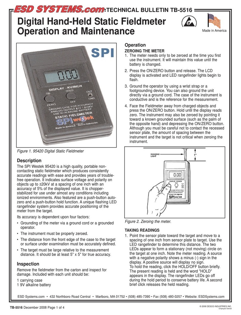
ESD SYSTEMS SPI Westek 95420 User manual

ESD SYSTEMS

ESD SYSTEMS SPI Westek 95420 User manual

ESD SYSTEMS SPl-20686 Instruction Manual

ESD SYSTEMS

ESD SYSTEMS SPl-20686 Instruction Manual

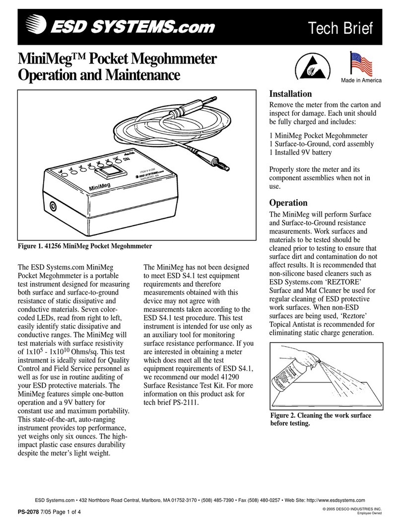
ESD SYSTEMS MiniMeg 41256 Installation guide

ESD SYSTEMS

ESD SYSTEMS MiniMeg 41256 Installation guide

Popular Measuring Instrument manuals by other brands

Milkotester MASTER LM2-P2 operating instructions

Milkotester

Milkotester MASTER LM2-P2 operating instructions

Ciret HPM 3000B manual

Ciret

Ciret HPM 3000B manual

DeWalt DW030PL-XJ user manual

DeWalt

DeWalt DW030PL-XJ user manual

Keysight Technologies M980xA PXIe quick start guide

Keysight Technologies

Keysight Technologies M980xA PXIe quick start guide

Johnson 40-6705 Operator's manual

Johnson

Johnson 40-6705 Operator's manual

ESCO Technologies ETS Lindgren 3701 user manual

ESCO Technologies

ESCO Technologies ETS Lindgren 3701 user manual

ENDEAVOUR ET0055A user manual

ENDEAVOUR

ENDEAVOUR ET0055A user manual

Performance Tool W80152 owner's manual

Performance Tool

Performance Tool W80152 owner's manual

Endress+Hauser Deltabar PMD55B Brief operating instructions

Endress+Hauser

Endress+Hauser Deltabar PMD55B Brief operating instructions

Flow vision FS20-dbEX Instructions for installation and adjustment

Flow vision

Flow vision FS20-dbEX Instructions for installation and adjustment

Fluidwell E126-P-EL manual

Fluidwell

Fluidwell E126-P-EL manual

FCI ST100 series manual

FCI

FCI ST100 series manual

palintest ChloroSense HR Quick test guide

palintest

palintest ChloroSense HR Quick test guide

Ankom A2000 Service Procedure

Ankom

Ankom A2000 Service Procedure

WIKA CPG1500 operating instructions

WIKA

WIKA CPG1500 operating instructions

Keysight M9485A Service guide

Keysight

Keysight M9485A Service guide

Magnetrol Jupiter JM4 Installation and operating manual

Magnetrol

Magnetrol Jupiter JM4 Installation and operating manual

Endress+Hauser Dosimag operating instructions

Endress+Hauser

Endress+Hauser Dosimag operating instructions

manuals.online logo
manuals.online logoBrands
  • About & Mission
  • Contact us
  • Privacy Policy
  • Terms and Conditions

Copyright 2025 Manuals.Online. All Rights Reserved.